Lv2 Electricity & Mag
 Call Kai
 Learn
Learn Practice Test
 Spaced Repetition
 Match
Match Flashcards
 Knowt Play
1/35

There's no tags or description
Looks like no tags are added yet.
Name | Mastery | Learn | Test | Matching | Spaced | Call with Kai | Chat |
|---|
No analytics yet
Send a link to your students to track their progress
36 Terms
Volts
The unit of voltage; equal to joules per coulomb.
one volt is the force require to drive one coulomb through a resistor of one ohm in one second
Watts
The unit of power; equal to joules per second.
Conventional current
The movement of charges from a positive terminal to a negative terminal.
Relationship between electrons, coulombs and amps
• Electrons are the tiny particles moving.
• Coulombs are how we measure the total charge they carry.
• Amps are how fast that charge flows per second.
So:
Electrons → carry charge → measured in coulombs → flowing per second → measured in amps
Work done means energy transferred.
If the electron moves to a different voltage, energy is transferred and work is done. Electron going around the hill.Therefore:
Work is done by (or against) the electric field.
The electron moves to a different voltage (potential difference).
Its electric potential energy changes.
If it moves across the field at the same voltage, no energy is transferred and no work is done. Electron going uphill or downhill. So:
The electric force is at 90° to the motion.
There is no component of force in the direction of travel.
No work is done by the electric field.
Since no work is done:
The electron's electric potential energy stays the same.
It remains on the same equipotential line.
There is no change in voltage.
Outline why a current-carrying wire experiences a force when placed inside a magnetic field.
The circular magnetic fields around the current carrying wire add and subtract to the preexisting magnetic field. This creates an area of weaker magnetic field on one side of the wire and an area of stronger magnetic field on the other side of the wire. The force on the wire will always be towards the weaker magnetic field.
7. Describe the concept of electromagnetic induction.
When a conductor is moved through a magnetic field so that the conductor crosses the magnetic field lines the electrons inside the conductor experience a Lorentz force (F = Bqv) and get pulled to one side of the moving conductor. This causes one side to become negative and the other side positive. This separation of charge is the induced voltage of electromagnetic induction.
8. Explain how a loop that is being moved through a magnetic field can have an induced voltage, but no current flowing around it.
If both the leading edge and the lagging edge of the loop are crossing magnetic field lines (the loop is entirely inside the B-field), then each edge will be producing an induced voltage. These induced voltages will be equal and opposite in the circuit, and trying to drive current in opposite directions in the loop, causing no current to flow around the loop.
9. Explain how a loop that is being moved through a magnetic field can have current flowing in one direction at one position, and that the direction of the current can be reversed at another position.
As a loop enters a magnetic field, only the leading edge crosses magnetic field lines. Only this leading edge will induce a voltage (V = BvL). This will cause current to flow around the rest of the loop not inside the magnetic field.
As the loop exits the magnetic field, only the lagging edge is still crossing magnetic field lines. The same polarity of induced voltage is created in this lagging edge (V = BvL). This voltage will cause current to flow around the rest of the loop in the opposite direction around the loop.
10(b). Outline three ways that the voltage can be increased.
Move the wire faster (v).
Have a stronger magnetic field (B).
Have a longer wire, all of which is crossing magnetic field lines (L).
What needs to happen in order for a current to be induced in a loop of wire moving through a magnetic field
There must be a change in the magnetic field.
So if you are moving the loop of wire side to side there will be no change in the magnetic field rather than moving the loop up and down or the magnet up or down.
How can you change the size of the induced voltage
Change the strength of the magnetic field. Stroger magnets - stronger magnetic field
move the wire or magnets more quickly. Faster the magentic field will change -
Shape the wire into a coil - more turns.
State a different unit for electric field strength
N C⁻¹ (newtons per coulomb)
This is because electric field strength can be defined as:
E=F/q
Explain how the force on the electron is affected as it moves from the midway point towards the anode.
The electric force is unchanged as the charge moves because the electric field is uniform (constant) between the cathode and anode as long as the voltage and separation distance is unchanged.
Describe how the force on the electron would be altered if the separation between the cathode and anode was halved.
If the separation distance is halved the electric field strength would double with the same voltage: E = V/d. This would make an electric force twice as large as before on the same charge: F = Eq.
On the diagram sketch the path that an electron would travel as it passes through the deflection plates.
The electron follows a parabolic path curving upwards towards the positive plate, then continues in a straight line when it leaves the region between the plates.

Describe the motion of the electron after it leaves the region of the deflection plates. Justify your answer.
The electron leaves the electric field with almost the same speed but with a new direction. The electric force on the electron is upwards while inside the electric field, and there are no horizontal forces on the electron. The electron follows a parabolic path, curving upwards inside the field then travels in a straight line when it exits the field.
Once the electron leaves the plates, there is no electric field anymore.
Therefore:
No force acts on it.
No acceleration acts on it.
Newton's First Law says it continues with constant velocity.
So it leaves along the tangent to the curve and travels in a straight line.
The electric field points from positive to negative, so:
Electric field = downward
A positive charge would be pushed downward.
But an electron is negative, so the force on it is opposite to the field:
Force on electron = upward
Therefore the electron curves upwards towards the positive plate.
Discuss the energy transformations that occur as the electron travels between the two plates.
The electron starts with electrostatic potential energy at the negative plate. This energy is converted into kinetic energy as the charge is accelerated by the electric force across the electric field to the positive plate.
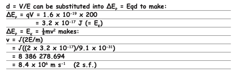
Using the data provided, and assuming that initially the electron is stationary. Calculate the speed the electron has at the instant it collides with the positive plate.

Question:
The motor runs most efficiently when it is supplied with 12 V. It is possible to increase the voltage the motor receives by adding resistors in parallel with the existing 200 Ω resistor.
Explain how adding resistors in parallel will increase the voltage to the motor.
Your answer should:
Discuss how adding resistors in parallel alters the total resistance of the circuit.
Link the new total resistance to the current flowing through the motor.
Relate this current to the required voltage.
The voltage used by the motor is determined by the current flowing around the series circuit and the resistance of the motor (Rmotor).
Since Rmotor is constant, the only way to increase the voltage across the motor is to increase the current. From V = IR, if R is constant and I increases, then V increases.
To increase the current flowing around the circuit, either the supply voltage must increase or the total resistance must decrease. Since the supply voltage is constant, the only way to increase the current is by decreasing the total resistance. From V = IR, if V is constant and R decreases, then I increases.
Adding resistors in parallel with the 200 Ω resistor creates additional pathways for current to flow. This reduces the equivalent resistance of that section of the circuit, making it easier for charge to flow around the circuit and increasing the current.
As the total resistance decreases, the current in the circuit increases. Since the motor's resistance remains constant, the increased current causes a larger voltage across the motor according to V = IR.

Question:
A different resistor is investigated for its properties and found to produce the following voltage/current graph.
Explain whether the resistor is ohmic or non-ohmic.
Your answer should include:
• A definition of ohmic and non-ohmic conductors.
• A justification as to how the graph illustrates whether the resistor is ohmic or non-ohmic.
This resistor is non-ohmic.
Ohmic resistors keep their resistance constant as voltage and current change, provided physical conditions such as temperature remain constant. Non-ohmic resistors have a resistance that changes as voltage, current, temperature, or other conditions change.
The graph of voltage against current is curved upwards rather than being a straight line. This shows that the resistance is increasing as the current and voltage increase.
Since the resistance is not constant, the resistor is non-ohmic.
If the graph were a straight line through the origin, the resistor would be ohmic because the resistance would remain constant.
Explain what the label 50 W 12 V means on a bulb
When the bulb is supplied with 12 V, it will produce 50 W of power. Any excess voltage may damage or blow the lamp.

State which lamp will glow the brightest in this series circuit. Explain your answer using words AND calculations.
Lamp A: 50 W, 12 V
Lamp B: 30 W, 12 V
Lamp C: 30 W, 6 V
Brightness depends on the power dissipated by each bulb. Since all the lamps are connected in series, the current through each lamp is the same.
Using P = I²R, the lamp with the greatest resistance will dissipate the most power and therefore be the brightest.
Lamp A:
PA = I²R
PA = (0.6756)² × 2.88
PA = 1.31 W ≈ 1.3 W
Lamp B:
PB = I²R
PB = (0.6756)² × 4.8
PB = 2.19 W ≈ 2.2 W
Lamp C:
PC = I²R
PC = (0.6756)² × 1.2
PC = 0.547 W ≈ 0.55 W
Therefore, Lamp B will glow the brightest because it has the highest resistance and dissipates the greatest power (2.2 W).

Explain why the current that flows through the ammeter in the series circuit is different to the current that flows through the ammeter in the parallel circuit.
Lamp A: 50 W, 12 V
Lamp B: 30 W, 12 V
Lamp C: 30 W, 6 V
In the series circuit there is less current (0.68 A) because the resistances add together to create a total resistance of 8.88 Ω.
In the parallel circuit there are three pathways for current to flow around the circuit, creating a smaller total resistance than any single resistor (0.72 Ω).
This creates a much larger total current (current drawn from the power source).
It = Vs / Rt
It = 6 / 0.72
It = 8.33 A ≈ 8.3 A
Therefore, the current is much larger in the parallel circuit because the total resistance is much lower.

State which lamp will glow the brightest in this parallel circuit. Explain your answer using words AND calculations.
Lamp A: 50 W, 12 V
Lamp B: 30 W, 12 V
Lamp C: 30 W, 6 V
Brightness depends on the power dissipated by the bulb (P = VI).
In a parallel circuit, each bulb receives the full supply voltage (6 V) because each branch is connected directly across the power supply.
The bulb with the smallest resistance will draw the largest current and therefore dissipate the greatest power.
Lamp C has the smallest resistance (1.2 Ω), so it will be the brightest.
PC = V² / R
PC = 6² / 1.2
PC = 30 W
PA = V² / R
PA = 6² / 2.88
PA = 12.5 W ≈ 13 W
PB = V² / R
PB = 6² / 4.8
PB = 7.5 W ≈ 8 W
Therefore, Lamp C will glow the brightest because it dissipates the greatest power (30 W).
Keeping the lamps connected in parallel, the student increased the power supply to 12 V. Bulb C blows (the filament melts) and it no longer works.
Discuss how this change in voltage will alter the brightness of the remaining lamps.
Since the circuit is a parallel circuit, all the lamps have the same voltage drop across them as the supply voltage. Therefore, all three lamps are provided with 12 V.
When lamp C blows, the other two lamps remain connected in parallel, so each still receives 12 V.
According to the lamp ratings, lamp A produces 50 W when supplied with 12 V, while lamp B produces 30 W when supplied with 12 V. Therefore, lamp A will be brighter than lamp B.
Because power is proportional to the square of the voltage (P = V²/R), doubling the voltage from 6 V to 12 V increases the power by a factor of four.
Therefore, lamps A and B will each be four times brighter than they were when supplied with 6 V.
Order from brightest to dimmest:
1. Lamp A
2. Lamp B
3. Lamp C (blown, no light output)

State what will happen when current flows through the rod. Justify your answer.
The rod will be pulled to the right because the current in the rod crosses the magnetic field lines at 90°.
Using the right-hand slap rule:
Fingers = magnetic field direction (downwards)
Thumb = current direction in the rod (slightly out of the page)
Palm = force direction (to the right)
Therefore, the force on the current-carrying rod is to the right.
At a particle level, moving electrons in the rod experience a magnetic force (Lorentz force) because they are travelling through a magnetic field. This produces a net force on the rod towards the right.

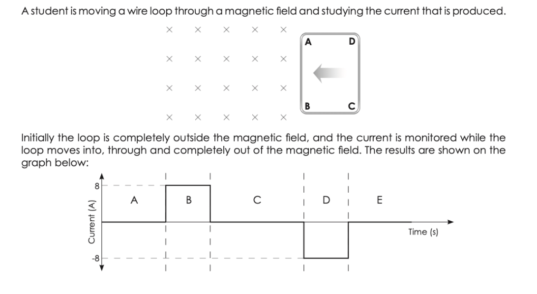
(d) Describe any induced voltages in the loop in the 5 stages that are indicated on the graph.
No voltage is induced in stage A because no parts of the wire loop are crossing magnetic field lines.
In stage B, wire AB is crossing magnetic field lines and a voltage is induced. A charge separation is created with B becoming positively charged and A becoming negatively charged. This induces a current of 8 A flowing anti-clockwise around the loop.
In stage C, both wire AB and wire CD are crossing magnetic field lines. Each wire induces a voltage, but the voltages are equal in magnitude and opposite in direction. As the induced voltages oppose each other, they produce no net voltage and no current flows around the loop.
In stage D, only wire CD is crossing magnetic field lines. A voltage is induced with C becoming positively charged and D becoming negatively charged. This charge separation causes a current of 8 A to flow clockwise around the loop.
In stage E, no voltage is induced because no parts of the wire loop are crossing magnetic field lines.

(e) Discuss what is happening to the loop with respect to the induced voltage in section C, and how that relates to the current in the wire loop.
Both wire AB and wire CD are crossing magnetic field lines, both inducing equal and opposite voltages.
These induced voltages try to drive current in opposite directions, and so no current flows in the loop.
(f) Use the right-hand slap rule to determine which direction of current flow has been graphed as positive. (Clockwise or anti-clockwise).
Loop entering magnetic field: anti-clockwise current. Graphed as +8 A.
Loop exiting magnetic field: clockwise current. Graphed as -8 A.

(g) The resistance of a wire loop is 2.5 Ω, side AB is 10.0 cm long and the loop is moving at 40.0 m s⁻¹. Calculate the magnetic field strength.
Induced voltage:
V = IR
V = 8 × 2.5
V = 20 V
Using:
V = BvL
B = V/(vL)
B = 20/(40 × 0.10)
B = 5.0 T
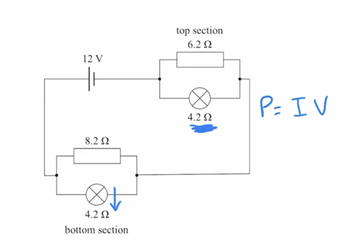
While both sections are working correctly, the lamp in the bottom section develops a fault and its resistance decreases. Use physics principles to explain what happens to the brightness of the other lamp.
The total circuit resistance will decrease and the ciruit current will increase according to V=IR. If the other lam’s R is constant while I increases, if more current is able to flow through the first lamp, the voltage it consumes will increase.
The total circuit V is always 12v, so the V in the bottom lamp will decrease. Brightness is described by power. Since P = IV, and both the V and I in the other lamp increase, so will the power and brightness.
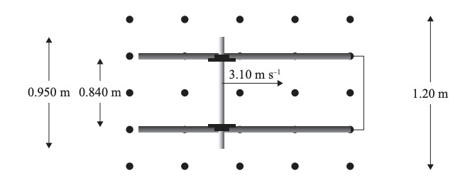
With the power supply still disconnected, a wire is connected between the rails, and the axle is given a push so that it is moving to the right at 3.10 m s–1
Describe the motion of the axle after it is set moving.Justify your answer using electromagnetism physics principles.
As the axle moves, it induces a downward current, which interacts with the magnetic field to produce a force to the left. This force opposes the original rightward motion, causing it to decelerate.
Motor vs generators
A motor uses electrical energy → mechanical energy.
Current is supplied to the coil.
The magnetic field exerts a force on the wire (motor effect).
The coil rotates.
Generator
A generator uses mechanical energy → electrical energy.
The coil is rotated by an external force.
The wire cuts magnetic field lines.
A voltage (emf) is induced.
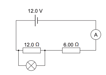
Bob has a lamp that operates normally only when connected to 8.00 V. He connects it in parallel with the 12.0 Ω resistor.
Without further calculation, explain why Bob’s lamp will not operate normally when connected this way.
Adding a lamp in parallel with the 12ohms resistor will create a extra pathway for the current to flow through so the overall current increases. Which means that the current through R2 will also increase. using V = IR, as the resistance is constant, more voltage is also required. Since R2 is using more voltage, it’s taking a bigger proportion of the 12V(Vs), which leaves less voltage for the components across the lamp and R1. This means that the lamp will not recieve the 8V it requires to function normally.