Systems 3/4 - Electronics 1
1/29
There's no tags or description
Looks like no tags are added yet.
Name | Mastery | Learn | Test | Matching | Spaced | Call with Kai |
|---|
No analytics yet
Send a link to your students to track their progress
30 Terms
Units - what is the measurement (from the calculation sheet) and base units name?
V / V (answer: Voltage in Volts)
I / A
P / W
R / Ω
E (or W) / J
N / (no base unit - in a calculation with voltage)
C / F
Voltage in Volts
Current in Amps
Power in Watts
Resistance in Ohms
Energy (or Work) in Joules
Number of turns (of a coil in a transformer)
Capacitance in Farads
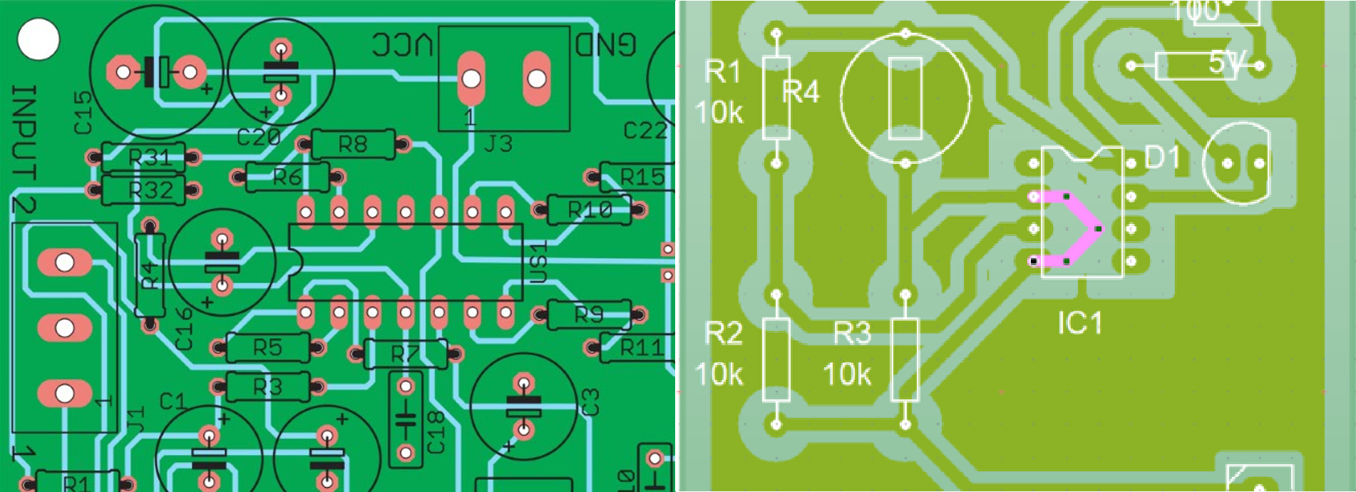
PCB
What does it stand for?
What is it used for? What are the identifying features?
Printed Circuit Board
Mechanically support and electrically connect electronic components using conductive pathways (traces)
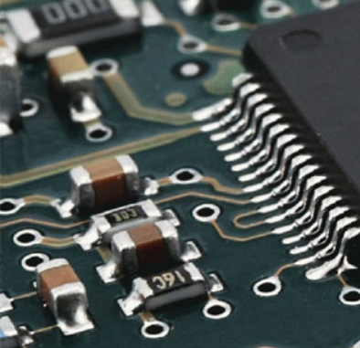
Surface mount (SMT)
Definition
Why use this?
A component that lays flat on the surface of a circuit board, with no protruding pins or leads.
Easy for machines to produce
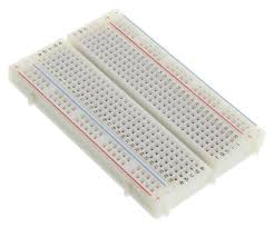
Breadboard
Definition
Why use this?
Rows of electrically connected holes in a board that jumper cables plug into
Easy to use for quick prototyping
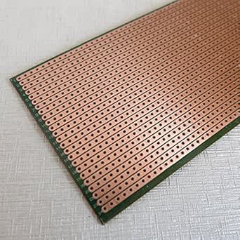
Veroboard
Definition
Why use this?
A grid of through holes (donut holes) that are often electrically connected in rows
Allows for soldering components by hand for better attachment than a breadboard.
What happens to current in series components?
What happens to current in parallel?
It stays constant through the circuit (All electrons pass through)
Shared/splits between branches (as a ratio of resistance)
Conductor (definition)
Insulator (definition)
A material that allows electrons to move through it easily
A material that does not allow electrons to move through it easily

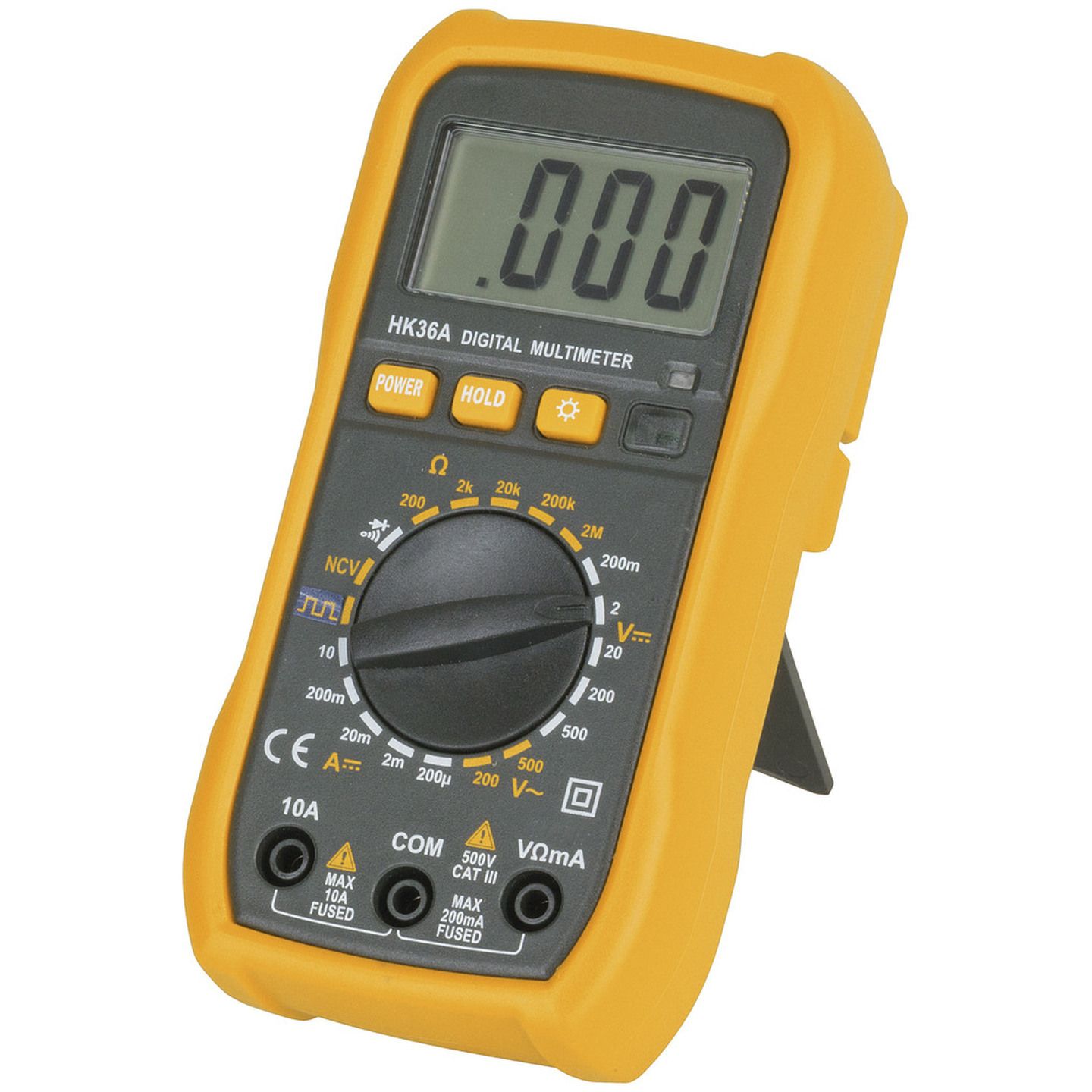
Multimeter - voltage
Steps to use?
Use case
Set the meter to the V with flat lines symbol, typically to the 20, probes placed parallel to component
To test voltage drop on component, or to test battery charge

Multimeter - current
Steps to use?
Use case
Set the meter to the A with flat lines symbol, the red probe needs to be on the 10A plug and set the dial to the highest setting, place the probes in series (break the circuit), a tiny reading will appear, then switch the plug back and change the dial one notch lower (bold is what is normally asked in the exam)
To typically test total current
(Rare)
Multimeter - continuity
Steps to use?
Why is this useful?
Set the meter to the arrow (diode) symbol, probes placed on opposite ends of component/wire being tested
Checks for conductive path (checking solders)
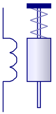
Solenoid
Description
Use case
Diagram symbol (lots of versions out there)
A coil of wire (inductor) around a metal rod which is pushed/pulled when a current passes through the wires
Electric door lock
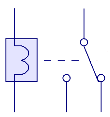
Relay
Description
Use case
Diagram symbol (lots of versions out there)
Is an electromagnet next to a mechanical switch
Used to electrically complete another (often high-power) circuit
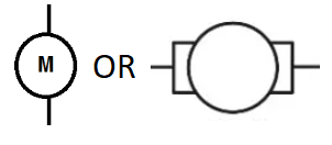
Brushed DC Motor
Description
Pros/Cons (compared to brushless)
Diagram symbol (two acceptable versions)
Convert electrical energy into kinetic energy through induction of a rotary coil which is connected to a split ring/brushes
Simpler, cheaper, less efficient, less powerful
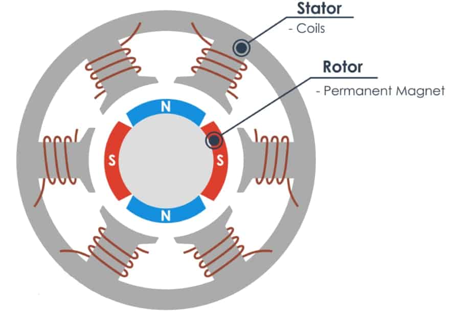
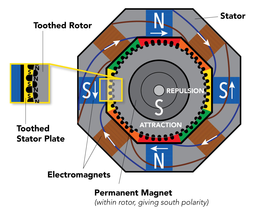
Brushless DC Motor
Description
Use case
Diagram (internals)
The stator and rotor don’t touch (no brush). Needs a signal wire to activate pairs of coils (stator) for speed. Gets the right alignment of magnets with hall effect sensors (mag sensors).
Drones (high power/weight)
AC induction motor
Description
Use case
Diagram (internals)
Produce motion from 3-phase Alternating current (looks similar to brushless, unless shown in 3D with squirrel cage)
Used for simple, high efficiency, high-power applications like factories (needs mains power)
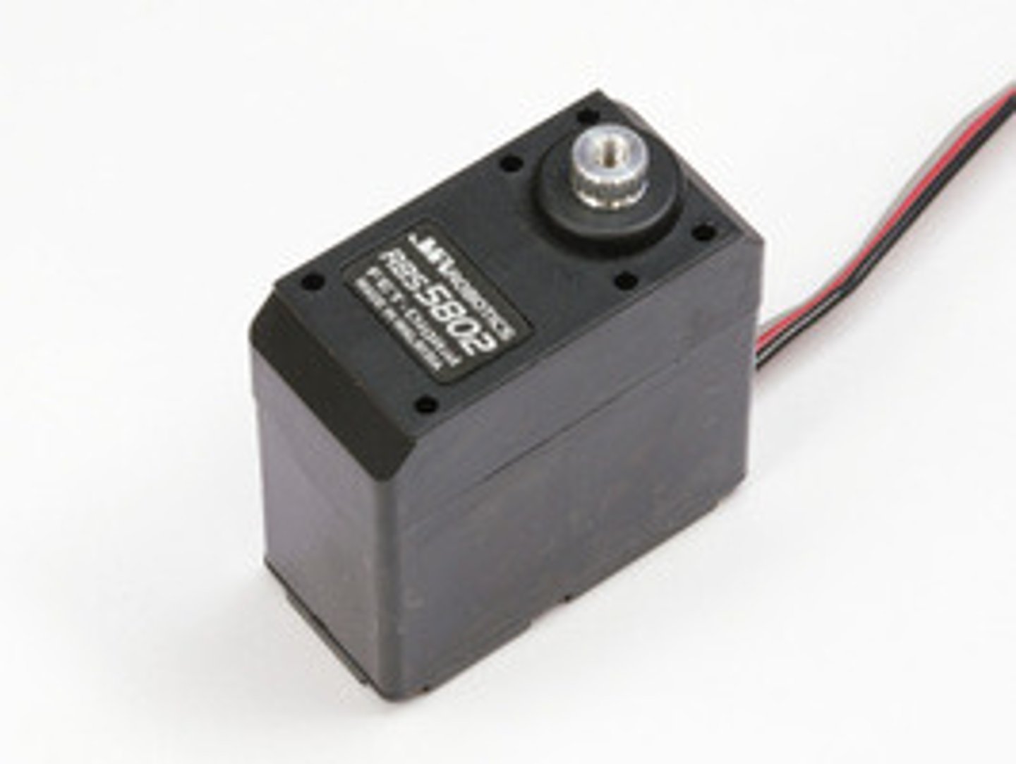
Servo
Description
Use case
Motor with precise angular position control. Controls position with 3rd signal wire
RC car turning, RC plane flaps adjustment
Stepper Motor
Description
Use case
(rare + tough) Diagram (internals)
A very angularly precise, high torque motor that can move in very small increments (eg: 1.2°)
3D printer, Lasercutter
Generator/ dynamo
Description
Use case
A motor that converts mechanical energy into AC electrical energy (AC induction motor)
Power generation plants
(rare)
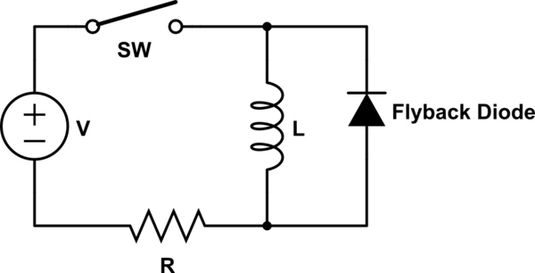
Flyback Diode
Description/ use case
Circuit diagram setup
Diode connected across any inductor (eg: motor) to prevent damage from excessive voltage discharge (motor still spinning after turned off).
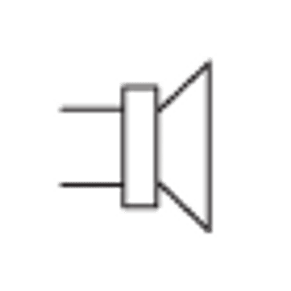
Speaker
Description
Diagram symbol
Converts electrical signals into sound with electromagnet and diaphragm
Microphone
Description
Diagram symbol
Reverse of speaker. Sound pushes on diaphragm causing electrical signal
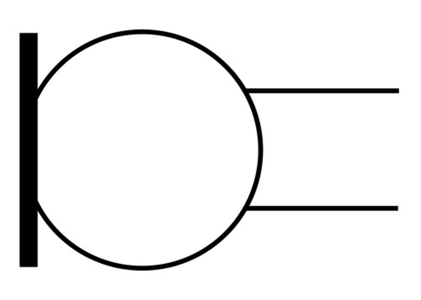
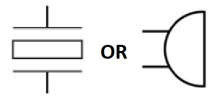
Piezo Buzzer
Description
Diagram symbol
Makes a predictable buzzing sound with electrical current applied to a specific crystal (NOT A SPEAKER)
Transformer
AC or DC?
Description
What kind of transformer terms are associated with an exam question?
Use case
Diagram symbol
AC only
Steps up or down voltage (current inversely) by the ratio of coils on each side (turns or number)
Primary coil 1000, secondary 500, 2:1, V1 = 230V, then V2 = 115V
Voltage is stepped up for transmission from powerplants, and stepped down once it arrives for homes

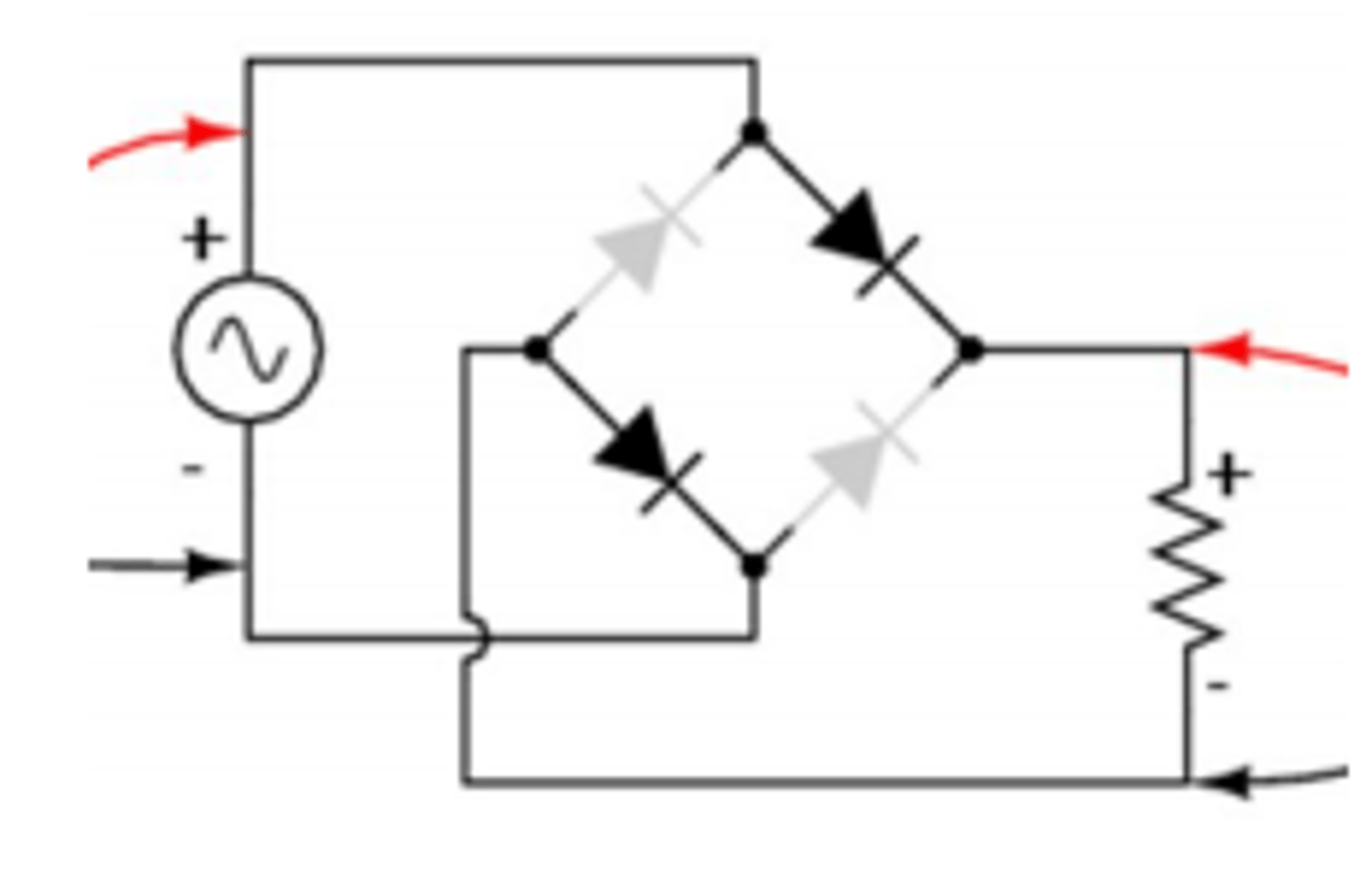
Full bridge rectifier
Description
Use case
Commonly added components? (3)
Circuit diagram setup
Made up of 4 diodes as in diagram
Used to convert AC to DC voltage
Transformer for step down AC, capacitor for smoothing, reverse bias Zener diode for clamping voltage
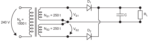
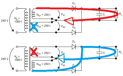
What is this and how is it different from a full bridge rectifier
What does the middle wire that splits the turns do?
How do you count the turns for the transformer?
It’s a simpler rectifier
Its the common ground, where the rectified DC always goes back to
The output turns are in two halves - one does positive voltage and the other does negative voltage, so you only have to count either the top or bottom
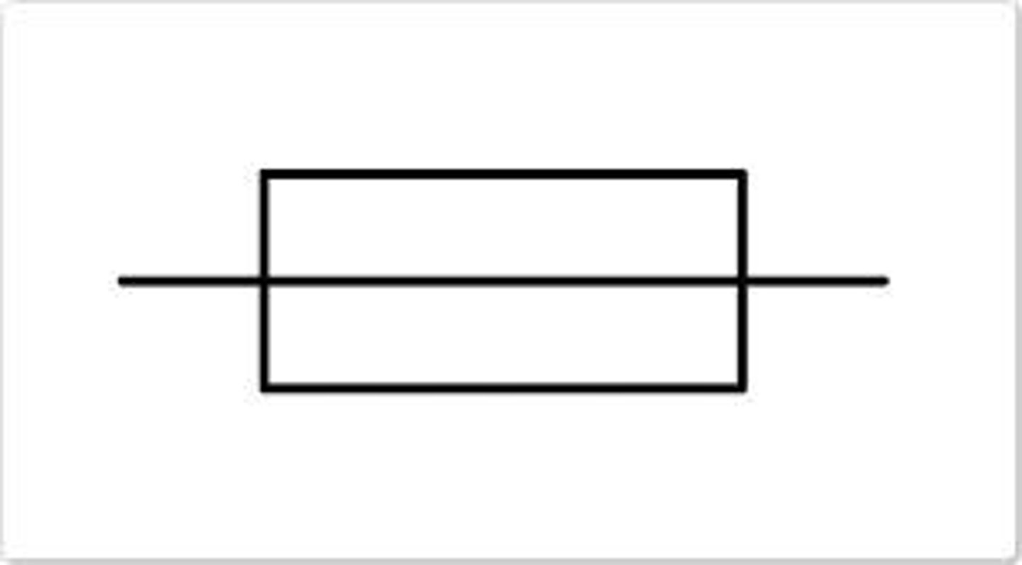
Fuse
Description
Use case
Diagram symbol
Thin covered wire that melts at a specific current level
Use in high-power circuits to protect delicate components.
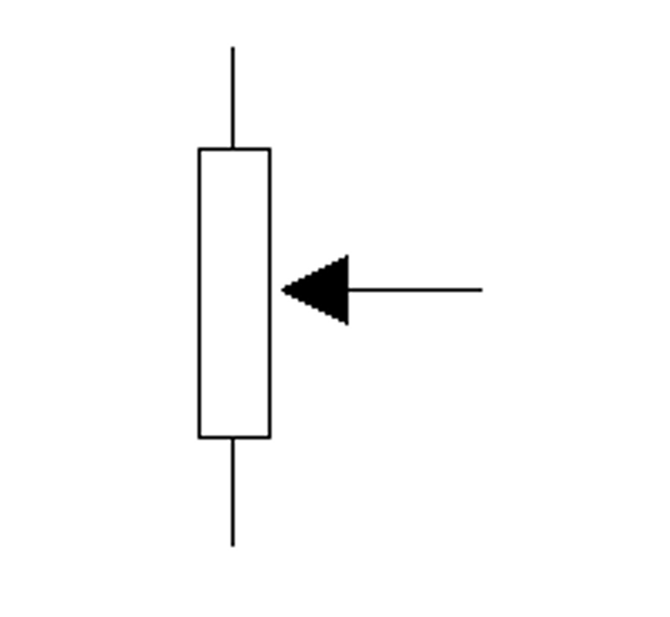
Potentiometer
Description
Use case
Diagram symbol
A three-terminal resistor with a sliding or rotating contact that forms an adjustable voltage divider
Volume control
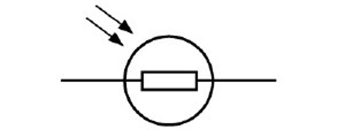
LDR
What it stands for
Description
Use case
Diagram symbol
Light Dependent Resistor
Changes resistance depending on the light intensity that falls upon it
Light sensor in a room
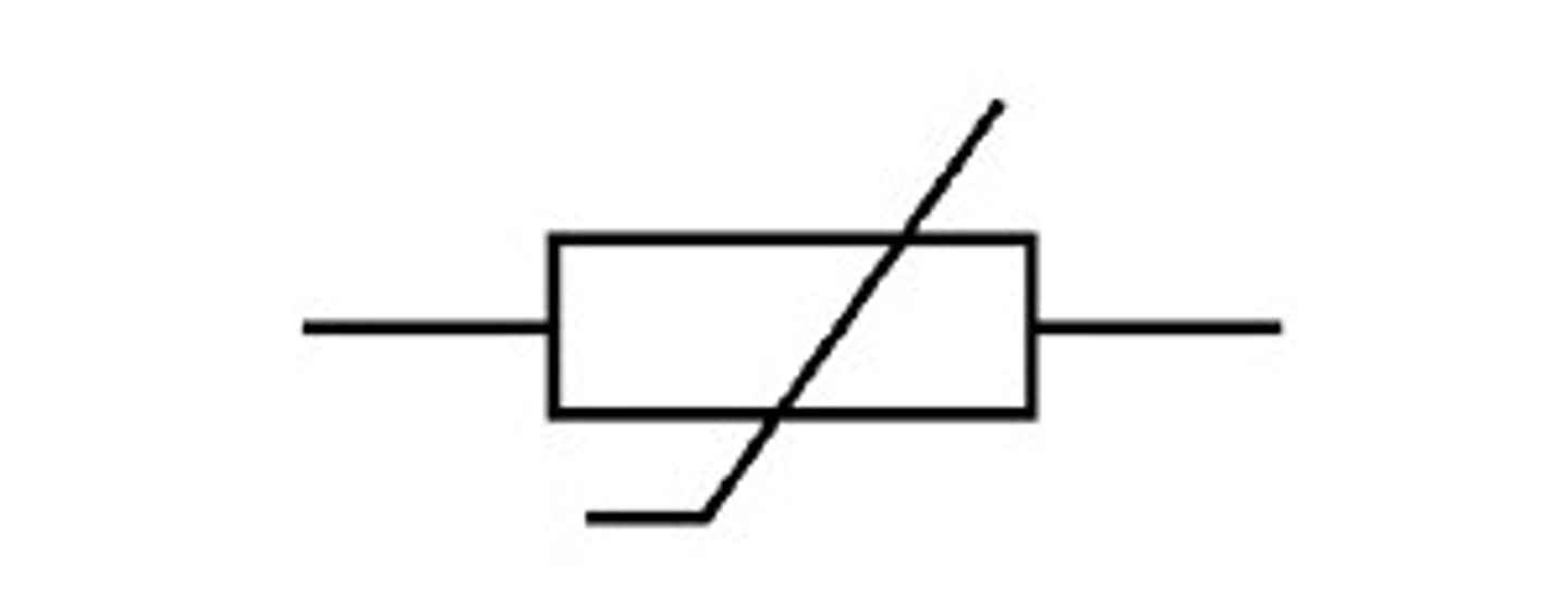
Thermistor
Description
Use case
Diagram symbol
A resistor that changes its resistance with a change of temperature
Temp control in a room
(Look out for the flick at the end of the diagonal line)
(rare)
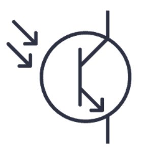
Photo transistor
Description
Diagram symbol
A component that electronically switches (or amplification) which relies on exposure to light to operate