Power Systems
1/34
There's no tags or description
Looks like no tags are added yet.
Name | Mastery | Learn | Test | Matching | Spaced | Call with Kai |
|---|
No analytics yet
Send a link to your students to track their progress
35 Terms
Constraints on Spacecraft Power:
Major limitations on space vehicle design since the beginning of the space age.
Early orbiting vehicles (US and Russia) relied on batteries with limited energy storage.
Batteries prevented operations beyond a few days, unsuitable for long missions.
Transition to Solar Power Arrays:
Solar power arrays emerged to meet the need for longer missions.
Solar arrays are not highly efficient but suited for spacecraft due to no consumables.
Life expectancy limited by component degradation, not fuel consumption.
Enabled spacecraft operating lifetimes of several years.
Batteries used for peak load requirements and energy storage during eclipses.
Power Systems in Unmanned Spacecraft: Majority powered by solar panels and batteries. Exceptions: short-lived battery systems, outer- planet missions with RTGs, Russian radar imaging satellites with nuclear reactors.
Power Systems in Manned Spacecraft:
Early manned spacecraft (Mercury, Gemini, Vostok/Voshkod) used batteries.
Later Gemini, Apollo CSM and LM used hydrogen/oxygen fuel cells.
Space shuttle uses hydrogen/oxygen fuel cells.
Russian Soyuz uses solar cells and batteries
similar to unmanned spacecraft.
Space Stations:
Salyut, Skylab, Mir, International Space Station use solar arrays for prime power generation.
Batteries used for load leveling and eclipse periods.
Limitations of Solar Power Systems:
Unsatisfactory for missions beyond the asteroid belt due to diffuse sunlight.
Outer-planet missions required new power sources. Development of RTGs:
RTGs convert heat from radioisotope decay into electricity via thermoelectric effect.
Independent of the sun, limited by component degradation and radioisotope half-life.
Useful for planetary surfaces with extended dark periods.
Used in outer solar system spacecraft (Pioneer,
Voyager, Galileo, Cassini), Viking Mars Landers, Apollo Lunar Surface Experiment Packages, some Earth orbiting spacecraft.
Nuclear Reactor Systems:
Offer high power in a compact package, independent of external environment.
Extensive development in the 1960s, terminated in the early 1970s due to funding cuts.
Revival of interest in recent years for long-duration
missions without adequate sunlight.
Russia continues to fly short-lived reactor systems; US has flown only one reactor test mission (SNAP- 10A in 1972).
Joint DoD/NASA/DOE SP-100 project delayed and
canceled due to high cost and limited applicability.
Importance of Power Systems in Spacecraft Design: * Major driver in spacecraft design, influenced by mission, system, and subsystem
*
considerations.
Interfaces with almost every other subsystem, requiring attention from systems engineers. Evolving technology with automation in routine functions and more efficient power
conditioning and control circuitry
Power System Functions
Primary Functions:
Generate and store electric power for spacecraft subsystems. Meet specific requirements for voltage, frequency, stability, noise limits, etc.
System-Level Tradeoffs:
Decide whether the power system should meet individual subsystem requirements or provide basic power for subsystems
to condition.
Example: High voltage for scientific instruments can be supplied
by the power system or a dedicated supply within the instrument.
Similar tradeoffs for cleanliness requirements (e.g., absence of
ripple, AC harmonic suppression).
Power Control and Conditioning:
* Control, condition, and process raw power from the primary source.
Ensure stable, uninterrupted power for the system's design life. Mission failure if the power system does not function as planned.
Power System Functions
Reliability and Protection:
Protect other subsystems from failures external to or within the power system.
Prevent short circuits in other subsystems from dragging down main bus voltage.
Implement failure protection to allow ontied functioning in a degraded mode after malfunctions.
Command and Telemetry:
Accept commands from onboard and external sources.
Provide telemetry data for monitoring operation and health.
Specialized Power Requirements:
Meet specialized power needs for functions such as firing ordnance
Power System Evolution
Growth in Power Delivery:
* Evolution from subsystems delivering a few watts
to tens of kilowatts or more.
International Space Station (ISS) initially required about 75 kWe.
Planned growth for ISS to 220 kWe or more. Trend Toward Higher Voltages:
Increased power demands lead to higher voltages.
Aim to minimize mass of spacecraft wire harnesses.
* Line losses and efficiency factors drive this trend. Design Lifetime and Complexity:
Design lifetime of space systems increases with required power levels.
More complex and expensive spacecraft demand longer lifetimes
Power System Evolution
Primary Power Source Choices:
Preliminary Concept Design:
Power level and lifetime changes influence choice of primary power source.
The figure illustrates operating regimes of various power sources.
Substantial overlap between regimes.
Other considerations may dictate power source choice beyond apparent optimum.
Figure provides a basis for preliminary concept design regarding power source choices
Power System Design Drivers
Design Considerations:
Various considerations affect power system design.
Table serves as a checklist for initial design and assessing impact of changes.
Customer/User Requirements:
*
Specific requirements such as size, observability, and operational constraints.
Limit choices for primary power source or other subsystem elements.
Target Planet and Distance from Sun:
* Design flexibility limited by available solar energy per unit area.
Need to control temperature of exposed surfaces.
Lifetime Requirements:
Operating environment impacts power system design.
Solar array degradation due to radiation exposure.
Gallium arsenide solar cells offer improved radiation tolerance
over silicon-based cells.
High radiation flux limits array lifetime.
Power System Design Drivers
Operating Modes:
Attitude Control Concept:
*
Different power levels required for various operating modes.
Percentage of time in each mode significant. Hybrid systems using multiple power sources or
energy storage types may be indicated.
Affects power system configuration constraints (solar arrays, waste heat radiators).
* Specific power needs of attitude control devices.
* Flexibility and frequency response of large arrays influence choice of attitude control effectors.
Historical examples of undesired control-
structure interactions due to solar array flexibility.
Attitude control system engineer involved in solar array orientation design.
Power System Design Drivers
Orbital Parameters:
Strongly affect primary power source choice and configuration.
Influence onboard energy storage requirements.
Planetary surface operations are
environmentally demanding and challenging for deploying large solar arrays and meeting energy storage demands.
Specific Mission Demands:
Rapid maneuvering spacecraft may not tolerate large, flexible solar arrays.
Low-observable spacecraft may preclude high- temperature operation concepts (e.g., RTGs)
Power System Elements
Functional Block Diagram:
The figure illustrates a typical spacecraft power system.
Identifies major elements within the power system.
Major Elements in Power System:
1. Primary Power Source: Solar arrays, RTGs, nuclear reactors, fuel cells.
2. Energy Storage: Batteries, capacitors, flywheels.
3. Power Conditioning: Converters, regulators, inverters.
4. Power Distribution: Bus bars, wiring harnesses, connectors.
5. Control and Monitoring: Telemetry systems, command interfaces, protection circuits.
Power System Elements
Power Source
Solar photovoltaic
Radioisotope thermoelectric generator (RTG)
Nuclear reactor, static or dynamic energy conversion
Radioisotope dynamic
Solar dynamic
Fuel cells
Primary batteries
Source control
Shunt regulator
Series regulator
Shorting switch array
Energy storage control
Battery charge control
Voltage regulation
Power conditioning
DC-DC converters
DC-AC inverters
Voltage regulation
Variety of Options:
Substantial variety of options exist within each power system element.
Table lists the most likely options encountered in normal spacecraft design practice.
Design Practice
Design practices vary by organization, but some rules are broadly applicable.
1. Direct Current Switching
Switches/Relays Placement:
Place switches or relays in the positive line to an element.
Direct connection to "ground" on the negative side.
* Allows power shut-off in case of short circuit or
high-current failure.
Gemini 8 Mission Example:
Aborted due to roll thruster stuck in "on" position.
Solder ball shorted thruster to spacecraft ground.
Rewired subsequent vehicles to switch thrusters in the positive control line
Design Practice
2. Arc Suppression
Location of Arc Suppression Devices: *Place devices close to the source of the arc.
*Avoid exposing conductive elements to ambient plasma.
*Ensure conductive paths between spacecraft elements to prevent differential charging and arcing.
Payload Module
3. Modularity
Extension Module
Propulsion Module
Modular Construction:
*Simplifies testing and replacement of failed units.
*Avoid excessive "stacking" of components to prevent collateral damage.
Favor access and maintainability alongside conservation of mass and volume.
Design Practice
4. Grounding
Grounding Practices:
Use common ground cable over individual grounding to structure.
Maintain high continuity between isolated structural elements.
Avoid "ground loops" to prevent voltage drops and ensure proper functioning.
Separate noisy power-switching ground lines from signal ground lines.
RF grounding requirements may differ but should ultimately tie back to primary structure.
* Isolate certain subsystems from electrical noise
if necessary.
5. Continuity
*Ensure good continuity between structural elements and thermal blankets.
*Minimize static electrical potential buildup or voltage differences.
6. Shield Continuity
* Shielding Practices:
*Maintain shield continuity across all connections.
*Prefer single-point shield ground to minimize shield current flow.
*Shield noise-sensitive or noise-generating circuits, sharing a common ground if possible
7. Complexity
*Avoid unnecessary complexity to reduce design, fabrication, and test costs.
Simple power supply bus voltages for subsystems to handle special requirements. Simplicity often preferred over mass and electrical efficiency for reliability.
*Adherence to simplicity recommended unless overriding requirements dictate otherwise.
Batteries
Batteries are the primary means of electrical energy storage onboard spacecraft.
Key Terms:
Charge Capacity (Cchg): Total electric charge stored, measured in ampere hours (Ah).
Energy Capacity (Ebat): Total energy stored, equal to charge capacity times average discharge
voltage, measured in Joules or watt hours.
Average Discharge Voltage (Vavg): Number of cells in series times cell discharge voltage.
Depth of Discharge (DOD): Percent of battery
capacity used in the discharge cycle.
Charge Rate (Rchg): Rate at which the battery can accept charge, measured in amperes per unit time.
Energy Density (Ebat): Energy per unit mass
stored in the battery, measured in J/kg or (W•h)/kg.
Battery Function:
Converts chemical energy directly to electrical energy.
Composed of a negative electrode, conductive electrolyte, and positive electrode.
Electrolyte can be liquid, paste, or solid (e.g., potassium hydroxide).
Chemical reaction ceases when the load is removed, but batteries degrade over time.
Battery Categories:
Primary Batteries: Higher energy and power densities, not rechargeable.
Secondary Batteries: Rechargeable, generally lower energy density
Battery Categories: Primary Batteries
Characteristics:
Often dry before activation, activated by allowing electrolyte to enter from a reservoir.
Thermal batteries activated by melting solid electrolyte with a chemical heater.
Used for quick-reaction power sources, pyrotechnic charges, and high power-drain devices.
Common Types:
Silver-Zinc (Ag-Zn): Excellent energy density, still widely used.
Lithium-Based Batteries: Highest energy density, early issues with explosions and corrosion largely resolved.
Battery Categories: Secondary Batteries
Characteristics:
Rechargeable, lower energy density, limited depth of discharge.
Commonly used in applications requiring multiple charge/discharge cycles.
Common Types:
Silver-Zinc (Ag-Zn): Good energy density, life limitations in high cycle applications.
Nickel-Cadmium (Ni-Cd): Standard for spacecraft applications, especially in LEO.
Nickel-Hydrogen (Ni-H2): High pressure, greater depth of discharge, better energy density, no reconditioning needed.
Nickel-Metal Hydride (Ni-MH): Uses metallic hydrides to contain hydrogen at low pressure, efficient packing, limited space applications due to cycle life.
Lithium-Based Secondary Batteries: Excellent energy density, some chemistries require reconditioning
Battery Voltage and Bus Systems:
Average discharge voltage (Vavg) is the product of cell voltage and number of cells in series.
Cell voltage typically 1.25-1.50 V, higher when fully charged.
US spacecraft systems commonly use 28 VDC bus voltage, reflecting early avionics heritage.
Trend towards higher voltage systems to reduce wire
harness weight and resistive losses.
Depth of Discharge and Charge Cycles:
* Tradeoff between battery mass and degradation due to deep discharge.
LEO spacecraft experience frequent charge/discharge cycles, requiring robust battery chemistry.
Ni-Cd batteries preferred for high cycle applications, limited
depth of discharge, periodic reconditioning.
Ni-H2 batteries offer advantages in depth of discharge and energy density, competitive for large spacecraft.
Orbital and Eclipse Considerations:
* Eclipse time affects battery usage and sizing.
* GEO spacecraft encounter eclipse seasons, requiring battery support.
* Dawn-dusk orbits and deep space vehicles may avoid eclipse but still need batteries for peak loads.
Battery Sizing Equation:
* Battery sizing based on power usage, depth of discharge, and charge capacity:
Charge rate constraints influence battery size and design. Although strict mathematical guidelines do not exist, a good rule of thumb for the allowable charge rate
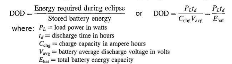
BATTERY SIZING EQUATION
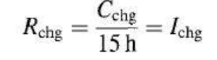
ALLOWABLE CHARGE RATE FORMULA
Nicad Reconditioning
Reconditioning Process:
Required to obtain maximum life from a Ni-Cd battery.
Involves deep discharge to voltage reversal, followed by controlled recharge.
Prevents rapid decline in battery voltage and usable depth of discharge.
Periodic reconditioning maintains steady-state voltage level.
Typically performed during full solar exposure between eclipse seasons.
Primary Power Source
Beyond Battery-Only Missions:
Operating Ranges:
*
Prime power source choice includes several possibilities beyond battery- only missions.
Governed by factors like power level, operating location, life expectancy, orientation requirements, radiation tolerance, and cost.
Figure shows suitable operating ranges for various prime power sources based on power level and lifetime.
Curves are broadly indicative, with substantial overlap indicating multiple feasible choices.
Other factors may bias the choice beyond mass, power, and lifetime requirements.
Increasing Power Requirements:
Spacecraft power requirements have grown over time.
Main bus voltage has risen to reduce conductor and component masses and resistive losses.
Figure presents data on past spacecraft and future predictions for civil and military applications.
Increased Lifetime Requirements:
Longer operational durations due to large investments in spacecraft and ground equipment.
Scientific spacecraft require longer lifetimes for distant or complex missions.
Life expectancy is crucial as most spacecraft cannot be serviced or refurbished.
Environmental Factors:
Access to adequate solar illumination is critical.
Solar arrays are not viable beyond Mars (1.5 AU) due to diffuse solar energy.
Concentrators can extend capability but are limited by the inverse-square law.
Radiation resistance is important as solar cells degrade with radiation exposure.
High-radiation environments (e.g., Van Allen belts) pose significant challenges.
Prime Power Sources:
Various prime power sources discussed in subsequent sections.
Capabilities and limitations of each source are considered.
Solar Arrays
Composition and Structure:
Made up of many individual cells on a substrate.
* Cells provide small current and voltage; series and parallel connections achieve desired output.
* Common cell shapes: rectangular (e.g., 2 x 4 cm), efficient packing with 90% density.
Early and Fixed Arrays:
Early spacecraft used arrays on the spacecraft skin.
Drum-shaped spinning spacecraft illuminated 40% of the array at a time.
Fixed arrays limited by launch vehicle dimensions, leading to deployable arrays.
Deployable Solar Arrays:
Semirigid paddle-like structures deployed after orbit injection.
Lightweight, rigid designs using composite materials.
Susceptible to handling damage; material thickness often dictated by handling needs.
Flexible Roll-Up Arrays:
* Thin cells and substrates enable roll-up and fold-up designs.
Example: 12.5-kW array on space shuttle mission STS-10.
Used on the International Space Station and other spacecraft.
Challenges with Flexible Arrays:
Flexibility can cause undesirable interactions with attitude control systems.
High voltage and power levels increase conductor mass and insulation needs.
Roll-up arrays offer low mass but have practical limits.
Reflective Concentrators:
Extend solar array capabilities beyond 1.5
AU.
Flat concentrator arrays for silicon cells increase collection area and energy conversion.
Gallium arsenide cell concentrators reduce cell area and increase operating temperature.
Complex and expensive to manufacture, complicate stowage and deployment.
Examples and Issues:
Deep Space 1 used Fresnel lenses for sunlight concentration.
HS-702 spacecraft used trough-type concentrators, later eliminated due to contamination issues.
Solar Cell
MAXIMUM AREA RECTANGLE
TEMPERATURE EFFECT
I-V Curve
knee
Transient Load Issues
Controlled load-shedding
Distance from Sun:
drops, farther
open circuit voltage
Mars orbiter
_______ Characteristics
TYPICAL ÇURRENT/VOLTAGE CURVE
MAXIMUM POWER POINT DEFINED BY _________ WHICH FITS WITHIN CURVE
DESIGN FOR NORMAL OPERATION AT MPP
LESS ENERGY AS SOLAR DISTANCE INCREASES
OPEN CIRCUIT VOLTAGE SAME
INVERSE CASE AS APPROACH SUN
MUST ALSO CONSIDER ___________
___________:
Typical shape important for spacecraft power system design.
Operate array at maximum power point to minimize mass and maximize efficiency.
Maximum power point lies on the _____ of the curve.
Defines series-parallel arrangement of cells in the array.
Transient Load Issues:
Transient loads can drive operating point off the knee of the curve.
Batteries help stabilize against such issues.
___________ can allow bus voltage recovery.
Distance from Sun:
Current ______ as array moves ______ from the sun;
___________ stays the same or increases.
Maximum power point shifts slightly with distance changes.
Design for maximum power point at target distance (e.g., ______).
Sun Tracking
45° TO 60°
Maximizing Power:
solar array.
Tracking Accuracy:
Two angular
Degrees of Freedom:
orbit plane.
normal to orbit plane.
____________________
CURRENT/POWER DECLINE AS SUN MOVES OFF NORMAL LINE
CURRENT APPROXIMATES COSINE TO ____ to ____ THEN FALLS MORE RAPIDLY
Maximizing Power:
Maximum power when sun line is normal to the array.
Cosine relationship between incidence angle and array output up to 60 degrees.
Modern spacecraft designed for sun tracking by ________
Tracking Accuracy:
Required accuracy not challenging; small increments preferred to minimize attitude disturbances.
________ degrees of freedom (DOF) needed for sun tracking.
Degrees of Freedom:
Alpha (a) Angle: Compensates for sun vector rotation in ______
Beta (ẞ) Angle: Compensates for sun vector component in ____________
Body rotation can supply one DOF;
full 2-DOF arrays often simpler for complex spacecraft.
Radiation
Effects
end-of-life
_____________
EXPOSURE to it REDUCES AVAILABLE POWER
It REDUCES O/C VOLTAGE AND S/C CURRENTS
Effects:
Radiation degrades solar cell efficiency over time. More severe degradation in high-radiation environments (e.g., Van Allen belts).
Solar array size based on _________ (EOL) capability, not beginning-of-life (BOL) performance.
Specific radiation environment assessed for each mission.
Radioisotope Thermoelectric Generators (RTGs)
thermoelectric effect.
Structure and Function
thermocouples
radioisotope canister
Efficiency:
10-11%
6-7%
Example
Galileo Jupiter Orbiter
doped silicon- germanium
plutonium-238 (238Pu)
86.7 years
Alternative Radioisotopes:
strontium-90
Operational Characteristics:
radioisotope decay and heat generation
Improbable Launch Failure Scenarios:
1986 Challenger
________________________
It render spacecraft independent of the sun.
Convert heat from radioisotope decay into electricity via the___________
Structure and Function
Central core of radioisotope material surrounded by __________
Hot side of thermocouples in contact with __________;
cold side with external wall.
Efficiency limited by thermoelectric elements and internal thermal conductivity.
Efficiency:
Modern semiconductor thermoelectric devices: __to__% efficiency.
Overall RTG efficiency: typically __to _% due to internal resistance and thermal losses.
Large amount of waste heat produced for each unit of electrical energy
Example:
______________ RTG: 298 W ± 10% at beginning of life, mass ~56 kg.
Thermoelectric elements: doped ______________ (Si-Ge).
Radioisotope:_________ (_____).
Half-life: ________.years
Degradation and Lifespan:
Major life-limiting factors:
thermoelectric element degradation,
insulator breakdown.
Alternative Radioisotopes:
Other candidates: ________ (90Sr) with adequate half-life and energy output.
Radiation type and energy affect shielding and electronics.
Operational Characteristics:
RTGs cannot be turned off; ________ and ______ are constant.
Control via external shunt regulator to manage excess electrical energy.
Stored in a shorted condition to reduce temperature during storage.
Challenges and Limitations:
High cost, particularly for radioisotope material.
Ground handling issues: high temperature and radiation require special equipment.
Increased installation time and radiation exposure for assembly crew.
Potential Earth contamination in case of launch failure or orbital decay.
Safety Measures:
RTGs protected against destruction and incineration.
Fuel elements encased in graphite for atmospheric entry and impact protection.
Extensive testing for environmental qualification.
Improbable Launch Failure Scenarios:
Most launch failures are benign (deflagration vs. detonation).
Example: __________ accident would not have dispersed radioisotopes.
Example: Military payload RTG recovered intact after launch abort.
Worst-Case Planning:
Extensive analysis to determine hazard environment and devise protection.
Minimize dispersion and allow recovery of radioactive material.
Special concern for plutonium due to its toxicity and radioactivity.
Radiation Impact on Spacecraft:
RTG radiation detrimental to electronics and instruments.
Units mounted on booms at a distance from spacecraft body, often with shielding.
Spacecraft must survive radiation exposure during stowed period with shielding and radiation-tolerant electronics.
Fuel Cells
Reactants:
Hydrogen and oxygen
pure water,
Efficiency
35%
Mass and Energy Density:
$3000 kW/h
Development Challenges:
Catalytic conversion
carbon
___________________
Direct conversion of chemical energy into electricity.
Operate more efficiently than batteries.
Oxidizer and fuel fed into the cell; catalytic material aids oxidation reaction.
Space Applications:
Primarily used in manned spaceflight.
First used in later
Gemini spacecraft,
Apollo CSM,
lunar module,
and space shuttle.
Reactants:
_____ and _____ used in operational fuel cells for space applications.
Output: ______ used for crew consumption.
Efficiency:
Laboratory demonstrations show conversion efficiencies approaching __%.
Mass and Energy Density:
Overall mass depends on desired operating time (includes reactant mass).
Energy density: 500 (W-h)/kg at 2.6 kW power level.
Cost: $_______/kW for commercial systems, higher for space-qualified systems.
Development Challenges:
Fuel cells run efficiently on pure hydrogen and oxygen.
Difficulty in storing and handling liquid hydrogen.
Interest in using
methane,
methanol,
ethanol,
natural gas for commercial devices.
_________ needed to free hydrogen;
______-based impurities hinder operation.
Direct Methanol Fuel Cells (DMFC)
methanol.
Regenerative Fuel Cells
hydrogen and oxygen
Solar arrays
Fuel Cells
______________ (DMFC):
Small power packs for portable applications.
High energy density, twice that of lithium-battery competitors.
Rechargeable by adding ______
Potential use in space suits and other space applications.
________________:
Potential for energy storage in large systems (e.g., International Space Station).
Use stored ________ to generate electricity during eclipse periods.
______ recharge fuel cells by electrolyzing water during illuminated orbit portion.
Hydrogen and oxygen stored for next eclipse period.
Demonstrated in laboratory, not yet reduced to engineering practice
Nuclear Reactor
Energy Conversion Techniques
Thermionics
thermoelectrics
Thermionic Energy Conversion
1600-2000 K
800-1000 K
10-15%
Radiators
Safety and Handling:
Reactors
Future Concepts: ____________
Viable for very large levels (hundreds of kilowatts to megawatts).
Heat from the reaction converted to electricity by various techniques.
Energy Conversion Techniques:
__________,
__________
Stirling, Brayton, Rankine cycle engines.
__________ Energy Conversion:
Converts heat to electricity by boiling electrons from a hot emitter (cathode) to a cooler anode.
Requires very hot cathode (_____- ____ K) and cooler anode (_____ - _____ K).
Power densities: 100-1000 W/m²,
efficiency: ___ to ___%.
High tolerance to heat and radiation, high reliability, compactness.
__________:
Required to reject waste heat to space.
Large radiators for high-power units present design challenges.
Dynamic conversion concepts more efficient, smaller reactor and radiator.
Safety and Handling:
_______ not highly radioactive until operation.
Intense radiation during operation requires heavy shielding.
Geometric separation used to reduce shield mass (e.g., shadow shield).
Mass-to-Power Ratio:
Improves with size.
Best for planetary surfaces, great distances from the sun, large power needs.
Renewed interest in space nuclear power options.
Dynamic Isotope Systems
Brayton, Rankine, or Stirling
alternator
Advantages:
500-700%
Future Concepts: ______________
Obtain more electrical power from isotope heat source used in RTGs.
Heat working fluid of ______, _____,______ cycle engine to drive ________.
Advantages:
Higher conversion efficiency (___ to ___%) more power from given isotope).
Reduces cost, radiation exposure, and mass.
Detrimental Factors:
Reduced reliability due to moving parts and vibration.
Larger radiator area needed for waste heat at lower temperature.
Testing:
Extensively tested but not yet flown.
Alkali metal thermal-to-electric conversion. (AMTEC)
electrons.
Future Concepts: AMTEC
_________________
Sodium heated to ionization applied to ceramic membrane conducting sodium ions but not _______
Efficiency
Potential conversion efficiencies approaching dynamic systems.
Challenges
Membrane life,
sodium condensation management,
materials concerns.
Solar Dynamic Systems
Brayton, Rankine, Stirling
electrical generator
Advantages:
100 kW
Future Concepts: _________
Machines (______, ______, _____cycle engines) driving _________ using sun as energy source.
Conversion efficiency five to seven times that of solar photovoltaic arrays.
Advantages:
Attractive at high power levels (above ____ kW).
Reduces attitude control and atmospheric drag problems.
Cost-competitive at high power levels.
Challenges:
Reduced reliability, possible vibration, attitude control system interactions.
Requirement for waste heat radiators may offset size advantage.
Radiators:
Current Concepts
metal.
conduction
Innovative Concepts
Droplet Radiators
Membrane Radiators
Rotating Band Radiators
Future Concepts: _____________
Importance:
Necessary to dispose of waste heat.
Significant for large systems, may be largest single item.
Current Concepts
Large thin skins, usually _____. -
Heat dissipation by ________, pumped fluid loop, or heat pipes.
Innovative Concepts:
__________: High performance, large surface-to-volume ratio, liquid-to-solid phase change.
Challenges: droplet generation and collection, materials selection.
__________: Fluid flows inside rotating membrane, enhanced by gas-to- liquid phase change.
Challenges: rotation requirement, material selection, launch configurations.
___________: Continuous loop of high-temperature metal moving between heated rollers.
Challenges: effective heat transfer to the band