Electrical and Electronic Systems
 Call Kai
 Learn
 Practice Test
 Spaced Repetition
 Match
 Flashcards
 Knowt Play
1/391

Earn XP
Description and Tags
All topics combined into one set - I recommend doing each topic separately first
392 Terms
q
Charge, measured in Coulombs (C)
i
Current, measured in Ampere (A)
v
Voltage, measured in Volts (V)
W
Energy, measured in Joules (J)
p
Power, measured in Watts (W)
R
Resistance, measured in Ohms
C
Capacitance, measured in Farad (F)
L
Inductance, measured in Henry (H)
Current
Rate of flow of charge past a point (coulombs/second, or amperes)
Voltage
Energy change per unit charge moving from point B to A (joules per coulomb, or volts)
Direct Current, DC
Constant current with time
Alternating Current, AC
Current varies over time
Element Absorbs Energy
Flow from positive → negative (for power)
Element Supplies Energy
Flow from negative → positive
DC Voltage
Constant voltage with time
AC Voltage
Voltage varies with time
Max Sink Current
Amount of current that can flow into a component without damaging it
Ground Current
VC = 0V (reference point)
Floating
Non-grounded, can accumulate static charge hence don’t know potential relative to ground
Power
Rate at which energy is absorbed (joules/seconds, or Watts)
Passive Reference Configuration
Current reference direction flows into positive reference polarity (thus p = v x i)
Element Absorbs Power (load)
p > 0
Element Provides Power (source)
p < 0
Conservation of Energy (Power)
Sum of instantaneous power into all elements in a circuit must equal 0.
Node
Point where 2 or more elements join (point of common voltage)
Kirchoff’s Current Law (KCL)
Sum of currents entering any node is 0.
Kirchoff’s Voltage Law (KVL)
Sum of voltages around any loop is 0.
Series
Same current flow through elements, but voltage can be different
Parallel
Same voltage through elements, but current can be different
Voltage Source (DC and battery)

Resistor

Capacitor

Inductor

Impedence

Diode

LED

Zener Diode

Transistor

Operational Amplifier

Resistor Properties
Limit current, convert potential energy to heat/noise, induce a voltage drop
Ideal Resistor
Characteristic plot of I against V is straight line w/ slope of 1/R
Conductance
Reciprocal of resistance (siemens, S)
Open Circuit
Zero conductance, infinite resistance (hence, v=0)
Short Circuit
Zero resistance, infinite conductance (hence, v=0)
Power Rating
Maximum power (in Watts) that a resistor can take before becoming damaged
Voltage Source
Produces a voltage across its terminals, may be constant or a function of time
Properties of Voltage Source
Will deliver any amount of current needed to maintain voltage
Current Source
Produces a specified current regardless of voltage across it, may be constant value or function of time
Zero Volt Voltage Source
Equivalent to short circuit (0 voltage regardless of current)
Zero Amp Current Source
Equivalent to open circuit (0 current regardless of voltage)
Incompatible Model
Ideal current source connected in series w/ source of different value

Incompatible Model
Ideal current source connected in series w/ open circuit

Incompatible Model
Ideal voltage source connected in parallel w/ source of different value

Incompatible Model
Ideal voltage source connected in parallel w/ short circuit

Compatible Model
Voltage sources in series can be combined

Compatible Model
Current sources in parallel can be combined

Real Voltage Source
As load draws more current, voltage across resistor increases, hence voltage available for load decreases
Controlled (Dependent) Sources
Output depends on a voltage or current elsewhere in the circuit
VCVS (Voltage Controlled Voltage Source)

CCCS (Current Controlled Current Source)

VCCS (Voltage Controlled Current Source)

CCVS (Current Controlled Voltage Source)

Resistors in Series
Req = R1 + R2 + …
Resistors in Parallel
Req = 1/(R1-1 + R2-2)
Voltage Divider
Find voltage across one of two resistors in series.
Current Divider
Find current across one of two resistors in parallel.
Ampere-hours (Ah)
Unit for measuring storage capacity
Stored Energy
Stored charge x voltage
Internal Resistance
Model the decrease in voltage due to increasing current as this (in battery)
Lower Internal Resistance
Supplies a load current with lower voltage drop
Measure open circuit voltage
How to find the value of supply voltage (Vs) of battery
Measure Terminal Voltage
How to find the value of internal resistance (Rs) of battery
Power Transfer
Efficiently transferring energy from a source to a load
Efficiency
Pout/Pin
Energy Loss
Proportional to I2R
Reduce I and R
Reducing energy loss in a circuit
Efficiency = 50%
Maximised Pout
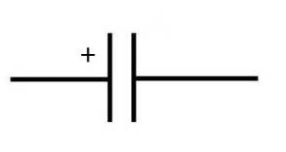
Capacitor
Device that stores charge and energy, comprised of 2 closely spaces parallel plates
Equal and opposite charges flow onto places
Effect of applying a potential difference over capacitor
Farads, F
Units for Capacitance, C
Capacitor at DC
Behaves like an open circuit
Ideal Capacitor
Charge remains indefinitely
Instantanenous change in voltage impossible
Condition for capacitor
RC Circuit
Contains a resistor and capacitor only
RC Circuit Properties
Capacitor will discharge, vc decreases, and resistor absorbs energy
Tau = RC
Time constant in an RC circuit
63%
Capacitor voltage decay after tau seconds in RC circuit
Capacitors in Parallel
Ceq = C1 + C2 + C3
Capacitors in Series
Ceq = 1/(C1-1 + C2-1 + C3-1)
Inductor
Device that produces a magnetic field around the wire when current passes through
Magnetic Flux Density
Proportional to current and number of turns (N)
Flux Density Changes
Potential difference is induced at terminals
Henries, H
Unit for Inductance, L
Inductor at DC
Behaves like a short circuit
Constant Current through Inductor
No induced potential difference, v(t)=0
Instantaneous change in current impossible
Condition for inductor
Energy Stored in Magnetic Field
Dependent on current and inductance, E(t) = ½Li2(t)
Current Increases
Energy in inductor is being stored
Current Decreases
Energy in inductor is being released
RL Circuit
Contains an inductor and resistor only