Exam 3 Concepts
 Call Kai
 Learn
 Practice Test
 Spaced Repetition
 Match
 Flashcards
 Knowt Play
1/76

There's no tags or description
Looks like no tags are added yet.
77 Terms
Transformers
electromagnetic device that changes an AC current from low voltage ←→ high voltage with minimal energy loss
uses electromagnetic induction to transfer electricity between circuits without any electrical contact or moving mechanical parts
Mutual Induction
primary side
voltage on primary side creates fluctuating magnetic fields due to the incoming AC supplied
secondary side
fluctuating magnetic fields cut the coils, inducing a voltage on the secondary coil
Principle of Operation
the changing magnetic field produced by primary coil induces an EMF in the secondary coil
induced EMF determined by # of coils on each side
Transformer Types
air core - 2 overlapping coils (least efficient w/ no core)
open core - core in each coil (lots of flux not used… leakage flux losing efficiency)
closed core - square donut w/ coils on opposite sides
shell type - closed + air cores combined w/ pillar down middle (most efficient)
Efficientmaxxing Cores
increasing core sophistication increases transformer efficiency
laminating the core steel reduces heat in the core & improve transformer efficiency
Step Up Transformers
increases voltage in secondary coil
decreases amperage (current)
secondary side has more coils than primary
Turn’s Ratio is >1
Step Down Transformers
decreases voltage in primary coil
increses amperage (current)
secondary side has fewer coilers than primary
Turn’s Ratio is <1
Transformer Law
the EMF induced in the secondary coil is to the EMF in the primary coil, as the number of turns in the secondary is to the number of turns in the primary coil
voltage change is directly proportional to the Turn’s Ratio
Turn’s Ratio
the number of turns in the secondary coil is to the number of turns in the primary coil: Ns/Np
fraction, whole number or ratio
Transformers and the Law of Conservation of Energy
Power In = Power Out
if voltage increases, current must decrease (to keep power constant, so compensation of either one)
Transformer Law: Voltage
voltage is DIRECTLY proportional to Turn’s Ratio: Vs/Vp = Ns/Np
Transformer Law: Current
current is INVERSELY proportional to Turn’s Ratio: Ip/Is = Ns/Np
Transitive Property
current change is inversely proportional to voltage change
Vs/Vp = Ns/Np = Ip/Is
Vs/Vp = Ip/Is
Autotransformer
operate on the principle of electromagnetic self-induction
single coil acts as primary and secondary
number of turns are adjustable
variable transformer either step up or step down
sends precise voltage to the primary side of the step-up transformer
Autotransformer Law
if the number of tapped turns is decreased, it will reduce the voltage on the secondary side, and vice versa
Power Loss (+ Efficiency)
transformers are 95+% efficient
Power Output/Power Input x 100
(2ndary V x I)/(primary V x I) x 100
Power Loss Causes + Prevention
power loss in a transformer is due to heat
copper loss: loss of power due to inherent resistance of copper (silver better)
to prevent, use larger diameter
eddy current loss: swirling currents that build up in the core
to prevent, spin until iron heats up, laminate & put in cooling oil bath
hysteresis loss: constantly changing magnetic domains in the core
Prevention (generally)
submerge transformer in an oil bath
laminate the transformer core
X-Ray Tube (Contains + Function)
Contains: thermionic vacuum diode
cathode
anode
Function: converts electrical energy into electromagnetic energy
Conditions to Produce X-Ray Photons
source of electrons (large amount)
high PD
vacuum
kVp
Kilovoltage Peak
beam: energy level (penetrability) of the X-ray beam
sets PD (voltage) between anode & cathode
mAs
Milliamperage per Second
beam: # of photons produced & length of exposure
sets the amount of current (or e-) per second during exposure
mA x exposure time (s)
X-Ray Circuits
Filament Circuit - determines filament current (mA setting)
current that heats filament
measured in Amps (low voltage & high amperage)
6-12 V & 3-5 A
Tube Circuit - determines the tube current during the exposure
passes between 2 electrodes & produces x-rays
measured in mA (high voltage & low amperage)
50-120 kV & 0.1.0.5 A
e- produced by filament are driven across the gap by the voltage applied to the cathode & anode
a small change in filament current produces a large change in tube current
Generator Divisions
Sections
low voltage (primary side)
high voltage (secondary side)
tube
Circuits
tube circuit (high voltage to tube)
filament circuit (high amperage, low voltage to filament)

Primary Side (Low Voltage)
adjusts incoming voltage to the technical factors we choose
tube circuit - adjust kVp
filament circuit - adjust mAs
Components
autotransformer
rheostat
kVp meter
timing circuit

Main Switch
2-Stage Switch
current to induction motor & filament
closes tube circuit & begins exposure
Autotransformer & kVp Selectors
variable transformer (single coil); adjusts incoming supplied voltage to the desired voltage for the X-ray tube (also operates using self-induction)
kV selector - taps on secondary side of the autotransformer
kV major - adjusts in units of 10
kV minor - adjusts in units of 1

kVp Meter
voltmeter that prereads the kVp going to step-up transformer (to be applied to the tube) & ensures correct voltage reaches it
wired in parallel
if there are voltage fluctuations, autotransmitter is adjusted (V not kV here)
lets you know if something is wrong

Timing Circuit
responsible for terminating the exposure

Rheostat
variable resistor (mA selector); adjusts incoming current to the desired amperage to be sent to the step-down transformer (filament)
3-5 amps & 6-12 volts

Focal Spot Selector
determines which filament receives current
dual focus tube

Step-Up (High Tension) Transformer
increases voltage (from autotransformer) to tube as it leaves from primary to secondary coil
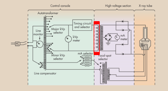
Secondary Side (high voltage) (distinction)
primary vs. secondary distinction made at step-up, high tension transformer
primary side - incoming volts adjusted by autotransformer
secondary side - high voltage to be sent to the tube

Step Down (filament) Transformer
sends increased amperage to filament for thermionic emission

mA Meter
measures tube current
wired in series on secondary side of high tension (step-up) transformer
mAs Meter (not in diagram) - needed for short exposure times less than 100 ms because ammeter will not measure it accurately

Rectification Circuit
converts AC → DC
enhances heating capacity of X-ray tube, permitting larger exposures

X-Ray Tube (+ Components)
utilizes high voltage to accelerate electrons toward the target and produce x-rays
filament - thermionic emission (boiling off of electrons when metal is heated)
cathode - negative diode to create high PD
anode - positive diode to create high PD

X-Ray Tube Function
Function: converts electrical energy into electromagnetic energy
large source of e-
high PD
vacuum
X-Ray Tube Envelope
Material: pyrex glass (older) or aluminum (easier to ground w/ less buildup)
Function: create vacuum
also tube port (window) which allows primary beam to exit
Cathode (parts + functions)
the negative electrode/diode
focusing cup - tungsten (or NICKEL?)
focuses e- cloud
prevents stem or off-focus radiation
filament(s) - thoriated tungsten
thermionic emission
dual focus: large & small focal spot size (FSS)
control for spatial resolution in images
Anode (parts + functions)
the positve electrode/diode
stationary - copper cylinder
rotating - molybenum disk (attached to rotor of induction motor)
high thermal capacity
high melting point
dissipates heat quickly
remains stable when heated at high RPM
Functions
supports target
dissipates heat
conduct current
Heat Units
kVp x mA x time x generator constant (1.45)
Factors Determining Heat During Beam Production
kVp
mA
exposure time
type of x-ray generator
Excessive Heat Build Up & Reduction
creates resistance in the tube circuit (lowers photon production)
causes damage to the anode & possibly the induction motor
Reduction: use lowest kV, mA & time combinations possible
Target (parts + function)
tungsten-rhenium alloy embedded in anode face
Function: to convert the kinetic energy of e- to electromagnetic energy (x-ray photons)
Tungsten Because…
high melting point: 6,192 °F
produces photon energies ideal for imaging
Rhenium Because…
stabilizes tungsten while it spins
Induction Motor
spins anode during exposure (3,000-10,000 RPM)
increases target area, spreading heat load surface area
rotor inside vacuum tube & held in place by a series of bearings
Tube Failure
most tube failure is due to heat build up within the tube
anode pitting and melting
wrong RPM or improper rotation
anode cracking
high heat exposure on cold anode/temp differences
induction motor damage (bearings)
molybdenum overheating moves onto rotor bearings w/o cooling time
tungsten vaporization
thin then breaks
filament breakage
can cause arcing/lightning
Life Span Determined By… (+ Extending Tube Life)
how it’s used
use lowest kVp, mA & time combinations
use appropriate warm up procedures

Label the Boxes
Left to Right (Top then Bottom)
induction motor rotor
molybdenum disk
tube envelope
anode
tube port (window)
tungsten-rhenium target
cathode
focusing cup
filament
Rectification
the process of changing AC → DC
(x-ray tubes operate most efficiently when supplied by high voltage DC)
AC Sine Wave
above: positive/forward bias
cathode to anode (- → +)
below: negative/reverse bias
anode to cathode (+ → -)
Valve Tube Rectifier (+ disadvantages)
simplest type of rectification
e- only flow from cathode to anode during positive pulses of AC current (no current during negative pulses)
Disadvantages
low heat capabilities
burnt out often
no longer used (replaced by solid state conductors)

What is this?
Valve Tube Rectifier
Solid State Rectifiers
semi-conductor used in diodes is silicon
impurities added to silicone to create two types of semiconducting material
P-Type: positive, electron holes (anode)
N-Type: negative, free/excess electrons (cathode)
currrent will only flow if e- pass from N → P
positive bias creates a PD b/t the two materials & negative bias removes the PD

What is this?
Solid State Rectifiers
Rectification Options (2 Waves)
half wave: suppressing the half of AC that lies below the line
full wave: change the negative half cycle to a positive one

Half Wave Rectification
60 pulses/sec
1/60 sec periods with no current/beam
leads to longer exposure times, high amount of low energy photons & higher patient dose

Full Wave Rectification
120 pulses/sec
no periods with no current
leads to a decrease of exposure time
Methods of Rectification (2)
self-rectification - half wave
diode rectification (valve tube or solid state of 1-2 diodes) - full wave

Self Rectification (+ Disadvantages)
simplest type of rectification
x-ray tube acts as its own rectifier
Disadvantages
low heat load capabilities
half wave rectification (aka single pulse)
no longer used

Diode Rectification Half Wave
diodes allow for better heat loading than self-rectification
1-2 diodes can provide half wave rectification
2 diodes are more efficient & increase heat loading more than one diode

Diode Rectifcation Full Wave
4 diodes can be used together to provide full wave rectification (aka 2-pulse rectification)
only one correct way to connect rectifier diodes to each other + x-ray tube + transformer
Half Wave vs. Full Wave Rectification
Half Wave
self-rectification
1-2 diodes
voltage drops to zero (1/60 sec)
lower efficiency (lower energy, more tube heat load & longer exposure time)
Full Wave
diode rectification only
no less than 4 diodes
more constant PD
higher efficiency (higher energy beam, less tube heat load & shorter exposure time)
Disadvantage of 4 Diode Rectification (+ corrections)
a large number of low energy x-rays are produced
correct with filtration
corrected with 3-phase or high frequency generators

Label Parts of the Diode
vertical line: cathode
bottom of triangle: anode
e- flow from right to left on this one (think megaphone)

3-Phase Current Production (+ 2 types)
generator with 3 armatures producing currents 120° out of phase (3 overlapping AC currents)
3-phase 6 pulse
3-phase 12 pulse (utilizes specialized high-tension transformer to double 3-phase current to tube)
Voltage Drop (ripple)
the percentage voltage decreases per cycle of current
any decrease in voltage decreases average photon energy and reduced the number of photons produced → heterogenous beam
Heterogenous Beam
creating a more heterogenous beam improves image quality, shortens exposure time & reduces patient dose
3-Phase Generators
x-ray generators that utilize incoming 60 Hz 3-phase AC to produce a more consistent primary beam
3-Phase Current at the X-Ray Tube
single phase half wave = 60 pulses/sec - 100% voltage drop
single phase full wave = 120 pulses/sec - 100% voltage drop
three phase 6 pulse = 360 pulses/sec - 13% voltage drop
three phase 12 pulse = 720 pulses/sec - 3% voltage drop
high frequency - continuous DC - < 1% voltage drop

3-Phase X-Ray Transformers
both types of 3-phase generators require
3 autotransformers for kV selection
step up (high voltage) transformers require
3 primary coils in a delta pattern
3-phase 6 pulse - 3 secondary coils in star (Wye) pattern
3-phase 12 pulse - 6 secondary coils one in each pattern
Compared to Single Phase: 1 secondary coil

3-Phase X-Ray Rectifiers
3-phase 6 pulse requires 6 rectifiers
3-phase 12 pulse requires 12 rectifiers
Compared To Single Phase: 4 rectifiers for full phase

Rectifiers (+ Devices to Test Rectification & Timers)
if a rectifier fails, radiographs will be under-exposed
most modern equipment will show an error or shut down if there is rectifier failure
3-phase generators & high frequency: oscilloscope
single-phase generators: spinning top
3-Phase Beam Production Pros
more constant PD
more homogenous beam
shorter exposure times
lower patient dose
Capacitor
device that stores a static electrical charge
measured in capacitance; Farad unit
discharge DC

What is this?
parallel plate capacitor - two charged plates separated by a dielectric
High-Frequency X-Ray Generators
generator utilizes a series of capacitors & transformers to convert pulsed AC into continuous voltage DC
nearly constant PD < 1% voltage
smaller (used for portable & CT)
more reliable
shorter & more accurate exposure times
High Frequency Generator Steps
AC enters rectifier → full wave pulsed DC
low voltage capacitor smooths voltage → low voltage DC
DC enters the inverter circuit → squared pulses of AC
square pulsed AC enters step up transformer → high voltage AC
high volt AC enters volt rectifier → pulsed DC
pulsed DC to high volt capacitor → smooth high voltage DC
smooth DC delivered to tube → nearly homogenous x-ray beam
High Frequency = …
constant beam