0 - Combined Set
 Call Kai
 Learn
 Practice Test
 Spaced Repetition
 Match
 Flashcards
 Knowt Play
1/101

Earn XP
Description and Tags
102 Terms
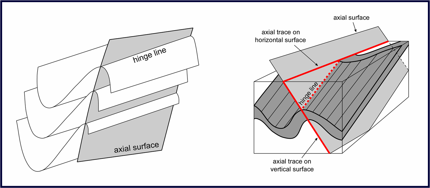
What is the distinction between the terms ‘axial plane’ and ‘axial trace’?
•The surface that contains the hinge lines of a nested stack of folded surfaces is called the axial surface (axial plane if that surface is planar)
•The line of intersection of the axial surface with any other surface of interest (usually the ground surface) is called the axial trace
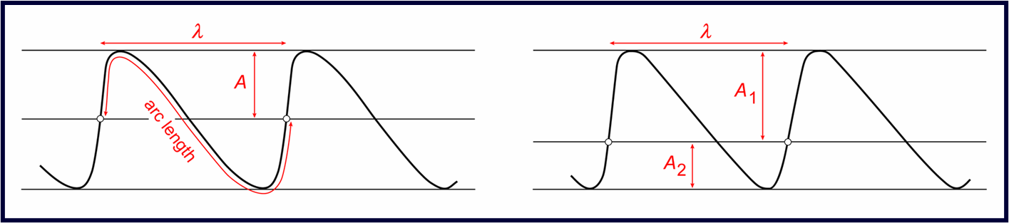
How do you describe the scale of folds
The scale of folds is characterized by their amplitude (A) and wavelength (λ) as defined with reference to the enveloping surfaces and median surface. Two other important measurements are:
arc length, defined as the distance measured along the folded surface between two inflection points or (as illustrated above) twice that distance, and
layer thickness
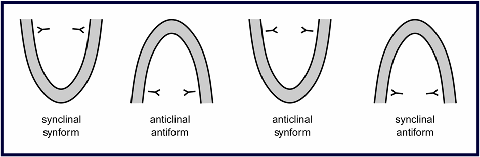
Define antiform, anticline, synform, and syncline
Folds that close down are synforms; folds that close up are antiforms. Folds that close horizontally are neutral folds
Folds with the youngest rocks in their cores are synclines; folds with the oldest rocks in their cores are anticlines
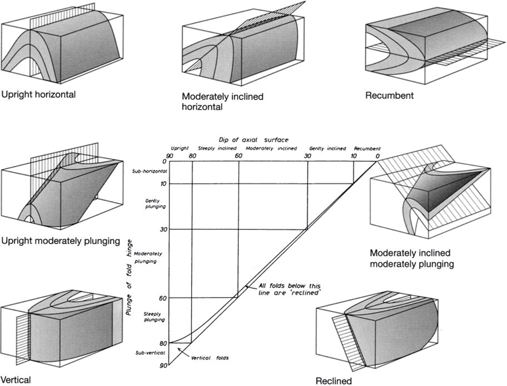
What is a recumbent fold?
The attitude of folds is described with reference to the plunge of the fold axis and the dip of the axial plane. Various adjectives are often applied
Recumbent folds have nearly horizontal axial planes with a plunge limit of 10 degrees and so form a neutral structure that is neither antiformal nor synformal
What is are isoclinal and chevron folds?
A fold is isoclinal when the fold tightness (defined by the interlimb angle) is 0-30 degrees
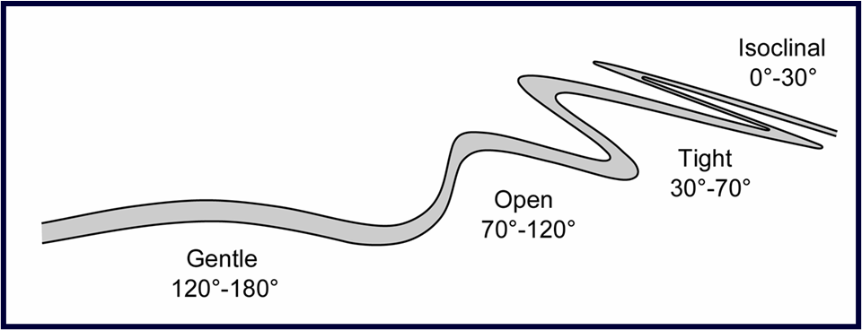
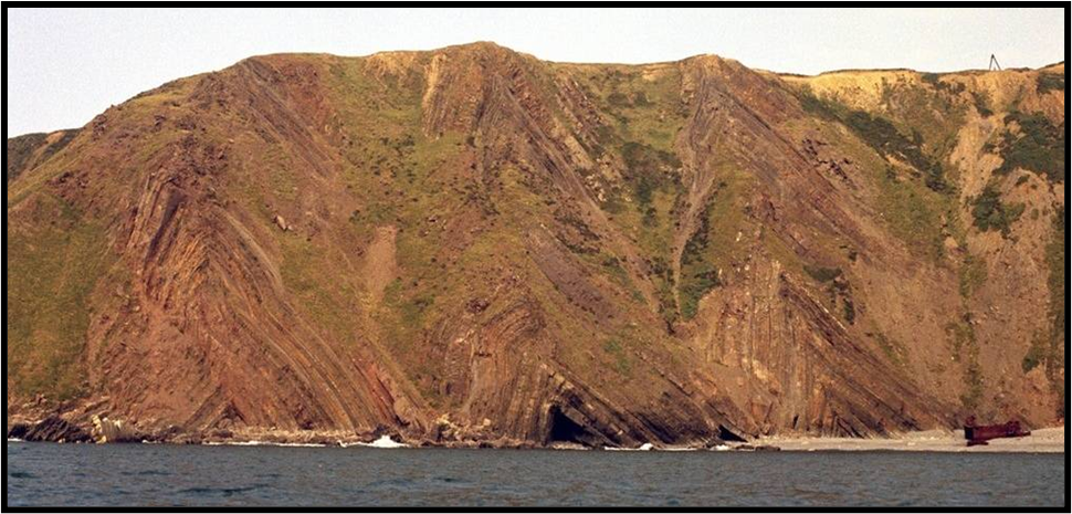
Chevron folds are a series of tight (0-60), angular folds that form repeating V-shaped beds with straight limbs and sharp hinges
What are parallel and similar folds?
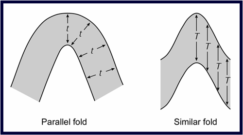
Parallel folds have constant orthogonal layer thickness around the fold
Similar folds have constant layer thickness parallel to the axial trace
What is a congruent minor structure?
The large-scale geometry of a fold may be established by examining small-scale structures around it
Primary structures including sedimentary structures and fabrics in igneous rocks (e.g., flow banding) provide an indication of orientation (particularly way-up) at the time the rock was formed
Secondary structures produced by deformation (e.g., minor folds, cleavage/schistosity)
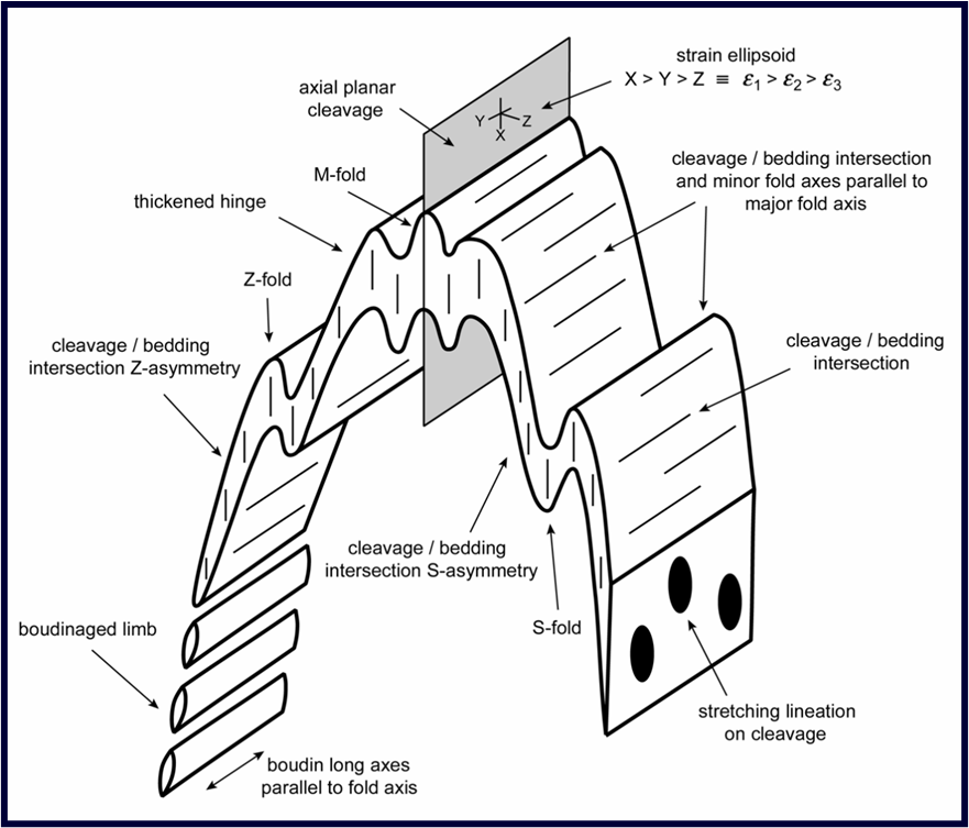
What is axial planar cleavage?
Cleavage = the fabric formed in fine-grained rocks up to a scale at which individual cleavage-forming minerals are visible to the naked eye (applies at low metamorphic grade)
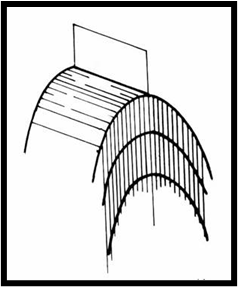
Cleavage/schistosity generally forms parallel or sub-parallel to the axial surfaces of folds. When it does, it is described as axial planar cleavage
Axial planar cleavage is invaluable for determining the orientation of the axial surface and also, by using the cleavage/bedding intersection, the fold axis orientation
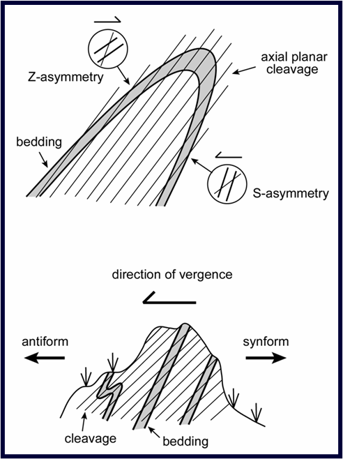
How is the asymmetry of both minor folds and the cleavage/bedding intersection lineations used to find the direction of the major antiform/vergence?
The direction of vergence of minor folds changes across the fold hinge, and so minor fold vergence (sense of asymmetry) may be used to locate this hinge
Axial planar cleavage helps determine the orientation of the axial surface, and by using the cleavage/bedding intersection, the fold axis orientation
The direction of vergence is obtained by establishing which way you have to rotate the top of the cleavage trace to make it parallel with the trace of bedding. Vergence direction points towards the antiform.
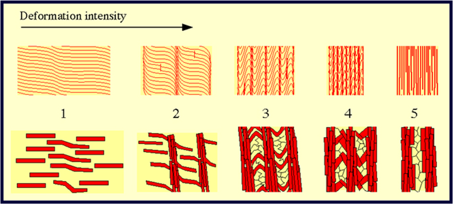
What is a crenulation cleavage?
The fine-scale layering of cleavage and schistosity means that if the rock is deformed for a second time, the cleavage or schistosity is refolded on a sub-millimetre to centimetre scale.
The hinges of these small folds are described as a crenulation lineation, and their axial planes as a crenulation cleavage
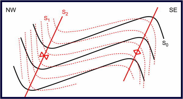
What do the following notations mean: S0, S1, S2, S1/S0, S2/S0, L1, L2, D1, D2, F1 fold, F2 fold.
S0 original surface (bedding). S1 first cleavage. S2 second cleavage (crenulation)
L1 and L2 refer to lineations formed in the 1st phase of deformation, 2nd phase of deformation, etc.
D1 and D2 refer to deformation phases 1, 2, etc.
F1 and F2 refer to folds formed in the 1st phase of deformation, 2nd phase of deformation, etc.
What is a stretching lineation?
Mineral elongation lineations formed parallel with the maximum extension direction of the structure on which they occur, are described as stretching lineations
Stretching lineations are parallel with the tectonic a-direction (transport direction) – the orientation of this direction may be at any angle to the fold axis within the axial plane
What is pinch-and-swell and what is the distinction between it and boudinage?
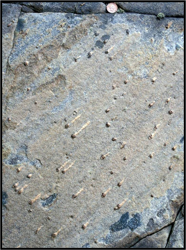
During folding, it’s not uncommon for the limbs to be attenuated. Gentle oscillations of the thickness of the bed are described as pinch-and-swell structures; if the layer is periodically separated, it’s described as boudinage
The shape of the boudins (block, barrel, fish-mouth) depends upon the contrast in competence with the adjacent layers
Boudin necks are frequently infilled with a secondary mineral deposit
The boudin necklines may be parallel with the fold axis
Boudins may be symmetric, or if formed in the presence of a layer parallel shear, asymmetric
The rotation of the boudins may be with the sense of shear (photo far right) or against it (figure below)

What are the essential geometric descriptors of folds?
The essential features that must be described (being quantitative whenever possible):
Antiform/synform, anticline/syncline, symmetry, scale (wavelength, amplitude)
Orientation of fold axis (plunge/plunge direction)
Orientation of axial plane (strike/dip)
Orientation of representative limbs (strike/dip of limbs at the inflection lines)
Interlimb angle
Orientation of bisector (strike/dip)
What is the difference between buckling, bending and passive folding?
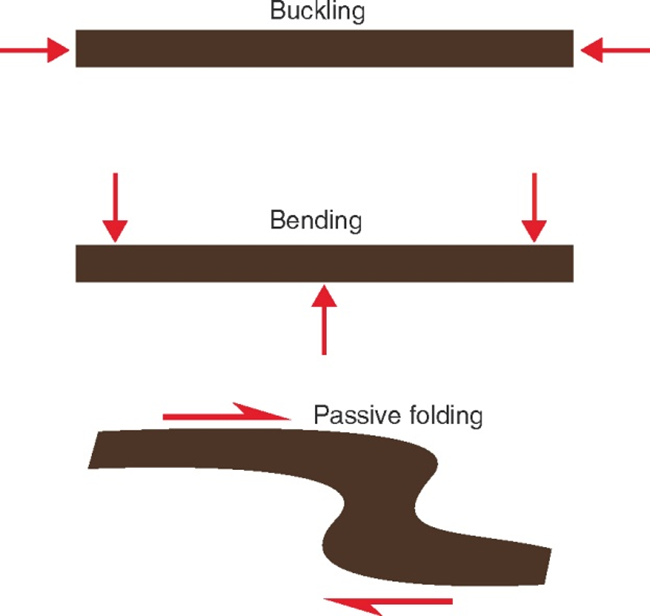
There are three basic types of folding:
Buckling: folding that occurs when layers are loaded parallel to the layering
Bending: folding that occurs when layers are loaded at a high angle to the layering
Passive folding: folding of marker bands that cross or are contained within a deforming unit
How does the wavelength of a single-layer buckle fold change with layer thickness and with the layer: matrix viscosity contrast?
Fold wavelength (λ) increases as layer thickness (d) increases
It is found that the effect of the folding disappears rapidly away from the folded layer (it’s negligible at distances of about one wavelength away)
It can also be shown that large viscosity contrasts lead to more rapid fold amplification and less layer thickening
How is pinch-and-swell an exception to buckle folding and what does it look like?
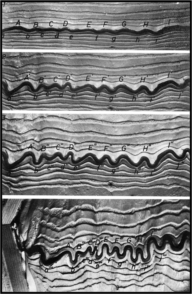
If the layer thickens and thins as in pinch-and-swell, then deformation is concentrated in the thin parts, and it is the spacing of these that controls the fold wavelength, not the layer thickness
The fold wavelength of a boudinaged layer is not, however, controlled by the width of the boudins
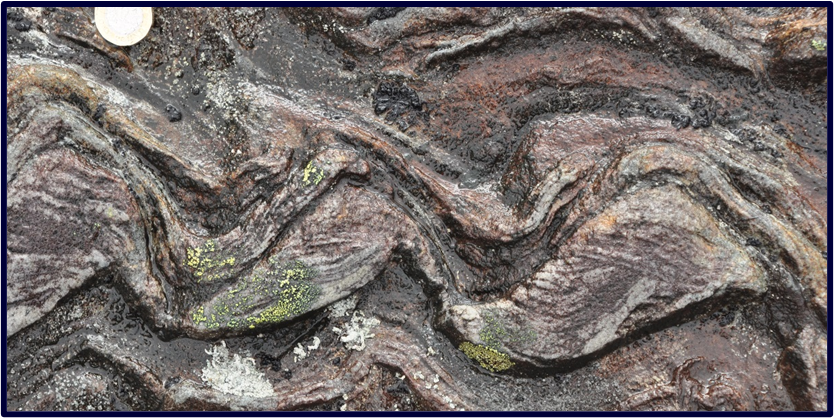
What is the distinction between harmonic, polyharmonic, disharmonic and ptygmatic folding?
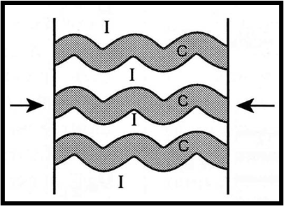
When the following equation for multilayer buckling is considered
λ = 2π d [ Nη L / ( 6η M ) ]1/3
Harmonic folding is where N is the number of competent layers in the package
Polyharmonic folding is a variant of the harmonic folding case that occurs when the competent layers vary markedly in thickness and/or in viscosity contrast with the matrix. In this case, folds with more than one wavelength develop, but the package conforms to the folding geometry of some controlling layer
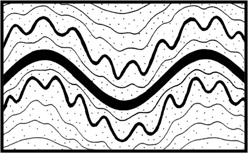
Disharmonic folding occurs if the competent layers are further apart than each other’s zone of influence (about one wavelength), then each layer folds independently
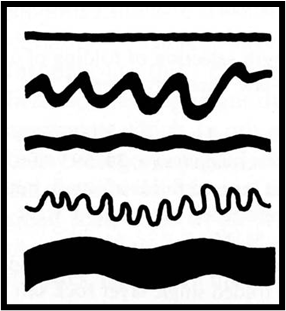
For Ptygmatic folding, if the relatively incompetent layers are much thicker than the competent layers, then the incompetent layers control the large-scale deformation. The thin competent layers take on a form in which the fold wavelength/layer thickness relationships are quite regular, but the fold axial surfaces vary greatly in orientation.
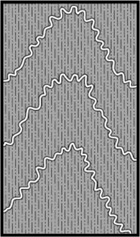
What is an accommodation structure and why does it arise?
Situations in which layers with thickness and/or viscosity characteristics that mean that they start to fold early and come to have limbs that are too long or short for the ultimate fold shape, are forced to adjust when the controlling layer starts to buckle
The structures that form to allow this adjustment are described as accommodation structures
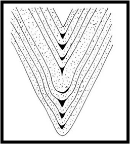
What are buckling kink bands and the different types of them?
Kink bands and folds with kink-like geometries have a Class 2 fold (similar fold) geometry, but the angularity of their hinges means that dip isogon methods cannot be used to describe them
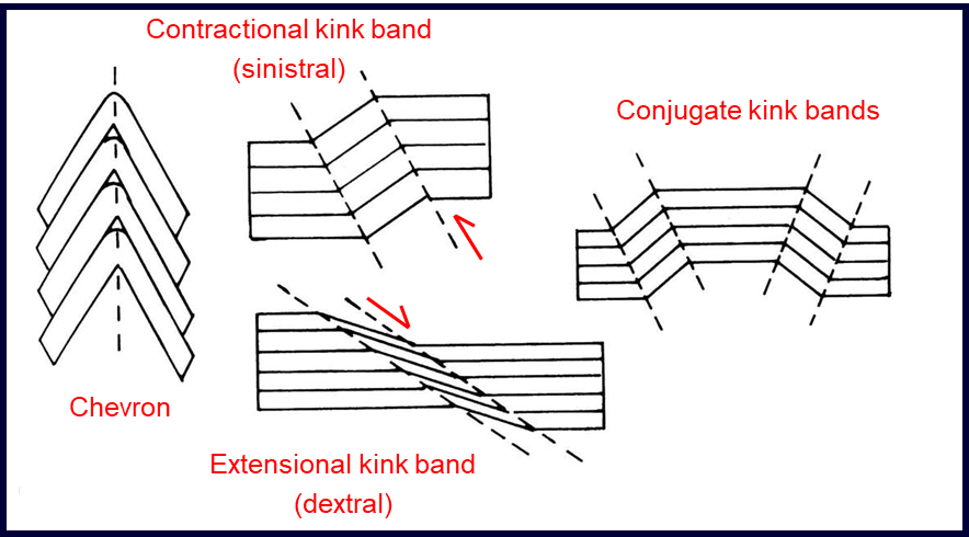
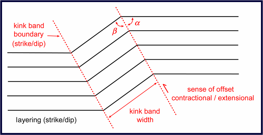
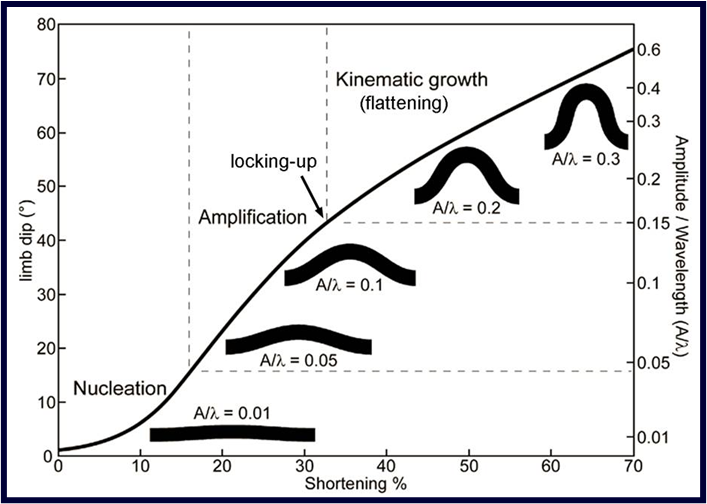
What are the four stages in the development of a fold?
Pre-buckle shortening (layer thickening)
Fold initiation (nucleation)
Fold amplification → locking up
Post-buckle flattening (kinematic growth)
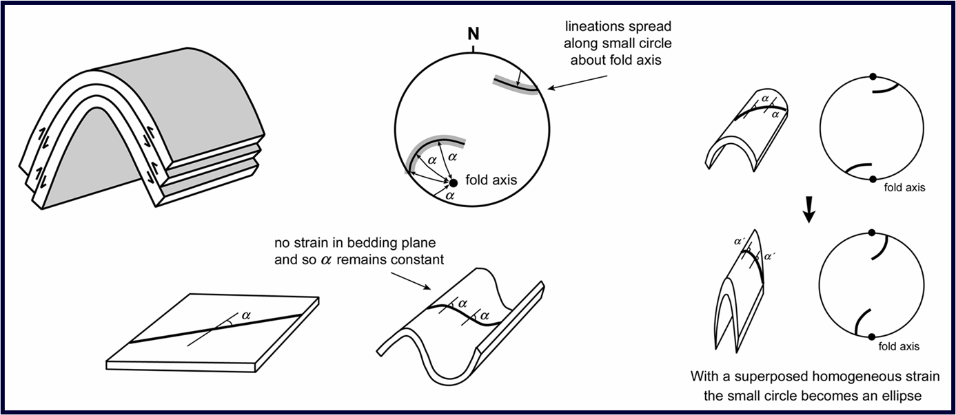
What is a flexural slip fold, and what happens (on a stereogram) to a pre-existing lineation when it is deformed by flexural slip folding?
During Flexural slip individual sheets slide over each other
Maximum slip is at the inflection points and decreases towards the hinge where it is zero
There is no distortion within the plane of the layering
The slip planes are usually bedding or some penetrative fabric such as cleavage
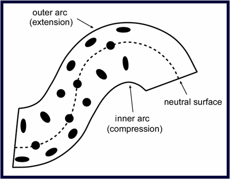
What is a tangential longitudinal strain fold?
What does the neutral surface separate?
In Tangential Longitudinal Strain (TLS) folding, the outer arc of the layer experiences extension and the inner arc experiences compression; between them is the neutral surface where the deformation cancels out
The maximum deformation is at the hinge and decreases towards the inflection points where it is zero
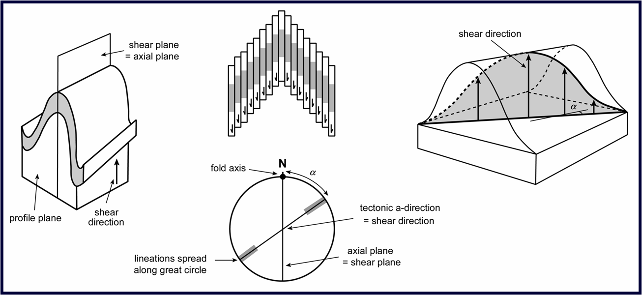
What is a shear fold?
A pre-existing lineation is spread along a great circle (on a stereogram) when it is deformed by shear folding. What is the significance of the intersection of that great circle with the great circle describing the shear plane?
During shear folding the shear planes are parallel to the axial surface of the fold
The influence of shear folding on a pre-existing lineation is to reorient it within a plane, and so on a stereogram the lineation is spread along a great circle.
The intersection of this great circle with the shear plane (axial plane) is the tectonic a-direction. If the folding is caused by shearing on a fault, this is the orientation of the fault slip vector
What is a pericline?
Folds do not go on until they wrap right around the Earth: they grow and die out along the fold axis or the fold hinge may bifurcate
This may happen on all scales up to that of the orogenic belt.
A common spatial arrangement is that of elongate domes (periclines) arranged in an en échelon array
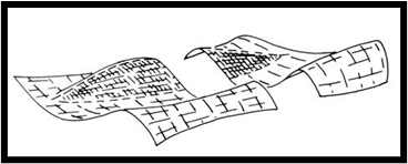
What is a sheath fold?
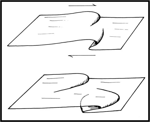
Folds with hinge lines that curve through more than 90° within the axial surface are described as sheath folds
•They are commonly associated with a strong stretching lineation
•Sheath folds form by passive amplification of some initial irregularity within a layer that is subject to layer-parallel shear
What is a fold interference pattern?
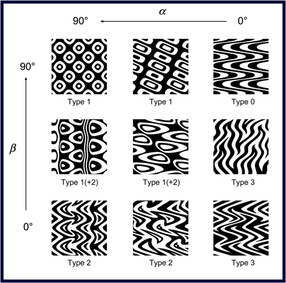
The outcrop patterns of refolded folds have been classified into four basic fold interference patterns according to the orientation of the fold axes and the axial planes of the two phases of folding relative to each other:
Type 0 is the coaxial and coplanar case – the 2nd phase of folding merely intensifies the 1st fold structure
In Type 1 refolded folds, the fold axes are at 90° to each other, both folds are upright with axial planes that are at 90° to each other. The result is a series of domes and basins
In Type 2 refolded folds, the fold axes are at 90° to each other, but one set of folds is recumbent and the other is upright. The result is a characteristic crescent or mushroom-shaped outcrop pattern
What is the definition of engineering strain, logarithmic strain, angular shear, and engineering shear strain?
Engineering strain (extension): e = ΔL / L0 = ( L - L0 ) / L0 where L is the final length of the line, and L0 is the starting length. It may be positive or negative depending upon whether the line has increased or decreased in length
Logarithmic strain (natural strain): ε = ln ( L / L0 ) = ln ( 1 + e )

The change in angle between two lines that were originally perpendicular is known as the angular shear, ψ. Angular shear is positive for an anticlockwise rotation, and negative for a clockwise rotation
Engineering shear strain γ = tan ψ. Gamma prime is also useful: γ´ = γ/λ

Explain the distinction between the terms ‘deformation’, ‘displacement, and ‘strain’
Deformation refers to displacement; it may or may not involve strain, e.g., rigid displacement of a body is deformation but it is not strain
Displacement describes the change in position of a given particle
Strain describes the relative change in position of particles within the feature, that is, it describes the change in distances between those particles. When these are small, strain is described as infinitesimal; when these are large (measurable) strain is described as finite
What are the four basic types of displacement? Which of these produce strain?
Rigid body translation – every particle in the body moves in the same direction and by the same distance
Rigid body rotation – uniform physical rotation of the body; the displacement vectors of the particles are not all the same (they depend upon the location of the particles relative to the axis of rotation) but the distance between particles remains unchanged
Distortion (shape change) – movement of particles so that they change position relative to each other; the displacement vectors are not all the same
Dilation (change in volume without change in shape)

What is a strain ellipse?
Strain in two dimensions is conveniently visualized using the strain ellipse. This ellipse represents the deformed shape of an initially circular marker, and illustrates how linear strain and angular shear vary with direction
There are two perpendicular directions (the major and minor axes of the ellipse) where the extensions are at maximum and minimum values and the angular shear is zero.
These max and min values are termed the principal strains, e1 and e2 (where by definition e1 ³ e2)

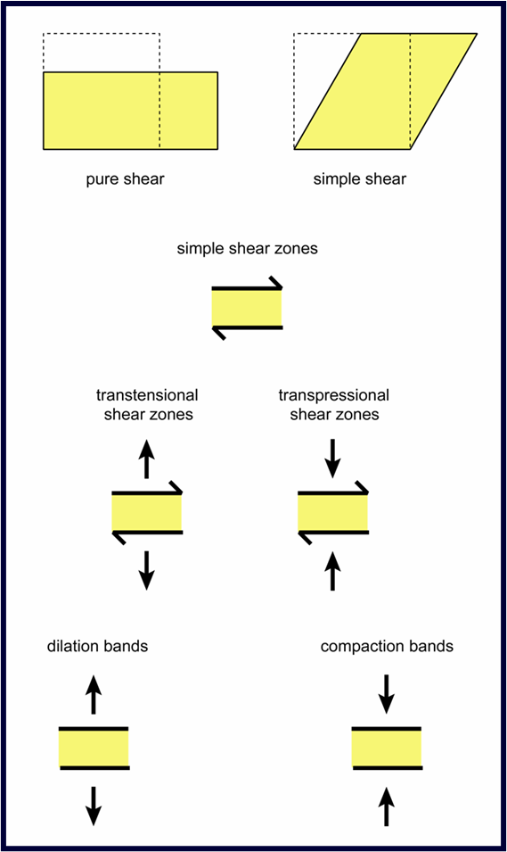
What is the difference between pure shear and simple shear?
Simple shear: in which the 2d body is subjected to a uniform shear parallel to some given direction without area change; the principal axes of strain rotate during the deformation, and hence such deformation is described as rotational and non-coaxial
Pure shear: extension or contraction involving no area change in which the principal axes of strain do not rotate; such deformation is described as irrotational and coaxial

Define ‘plane strain, and ‘axially symmetric strain’
Plane strain is when there is no stretching or shortening in one principal direction (Y direction); in such cases the strain can be regarded as two-dimensional
Axially symmetric extension or compression is an irrotational deformation in which the length changes along two principal directions (Y and Z or X and Y respectively) are equal

Using the X, Y, Z nomenclature, define a prolate and an oblate strain ellipsoid
The shape of the strain ellipsoid can be visualized by plotting RXY against RYZ (usually logarithms of these ratios are plotted). Such a diagram is called a Flinn diagram
A Flinn diagram separates strain ellipsoids that have prolate form (cigar shapes) from ones that have oblate form (pancake shapes)
Separating deformations dominated by extension in one direction from ones dominated by flattening in one direction

In the X, Y, Z nomenclature, what direction is a stretching lineation?
In moderate to high-grade deformed metamorphic rocks, the nature of the fabric provides the most immediate impression of the geometry of the strain ellipsoid.
If linear elements dominate (prolate ellipsoid), the rock is described as an L-tectonite
If planar elements dominate (oblate ellipsoid,) it is an S-tectonite.
Those with both a strong foliation and a strong lineation are LS-tectonites

In the X, Y, Z nomenclature, what plane is cleavage?
Cleavage in deformed rocks is generally assumed to represent the XY plane (principal flattening plane)
Within shear zones, cleavage tracks the XY plane across the shear zone

What descriptors are needed to specify the geometry of a fault (shear zone)
The orientation (strike/dip) of the shear zone walls
The orientation (plunge/plunge direction) of the slip vector
The magnitude and sense of displacement of the strike-slip and dip-slip components of the slip vector (displacement)
What is the distinction between simple shear, transtensional and transpressional shear zones
In low porosity rocks shear zones are often idealized as simple shear zones but real shear zones may simultaneously involve significant components of extension (transtension) or contraction (transpression) normal to their margins
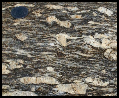
What are the defining features of the term ‘mylonite’?
In the middle of a shear zone, the strain may be so large that pre-existing textures are completely transposed. The resulting banded rock is described as a mylonite
Formally, mylonites are fault rocks containing a well-developed foliation that arises during tectonic grain size reduction
Mylonite zones can be up to several kilometres thick and may contain a rich variety of deformation features that are indicative of local variations in finite strain
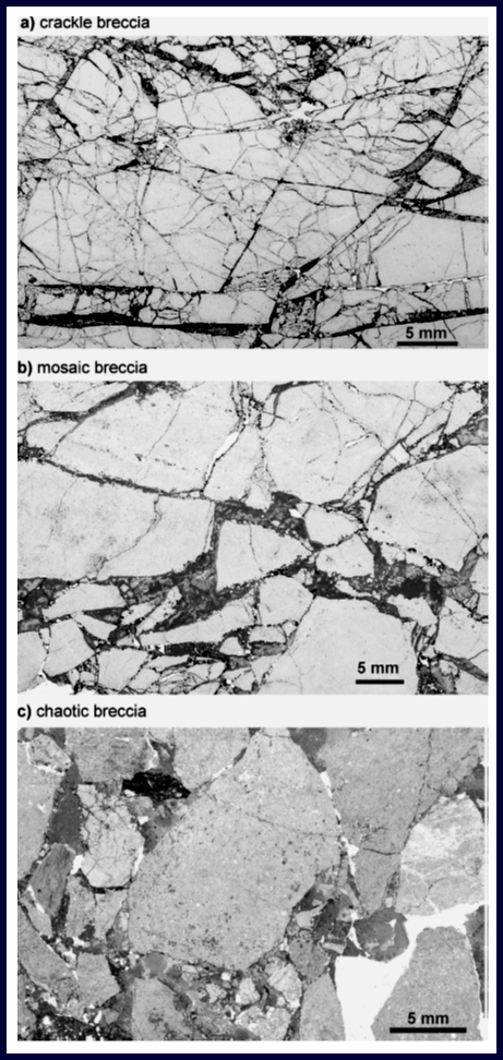
What are the defining features of the term ‘breccia’?
Fault breccias contain more than 30% clasts that are over 2 mm in size
They may be subdivided into crackle, mosaic and chaotic breccias depending upon how well the clasts fit together.
This subdivision effectively equates to the % clasts over 2 mm (crackle 100-75%; mosaic 75-60%; chaotic 60-30%)
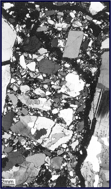
What are the defining features of the term ‘cataclasite’?
Cataclasites are all non-foliated fault rocks with less than 30% clasts over 2 mm that are not in the special categories of pseudotachylyte or fault gouge. [Foliated fault rocks of this clast size are mylonites.]
They may be subdivided into protocataclasites (0-50% matrix), mesocataclasites (50-90% matrix) and ultracataclasites (90%+ matrix) – in each case the matrix comprises any clast that is < 100 µm
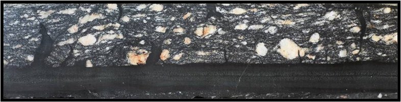
What is a pseudotachylyte?
Pseudotachylytes are cataclasites that contain dark glass (or its devitrified product)
The glass forms by localized melting during rapid sliding (earthquakes). This melt may be injected into the wall rock
Pseudotachylytes typically occur as mm- to cm-wide zones that have sharp contacts with the host rock
What is a ‘fault gouge’?
Fault gouges are fault rocks with less than 30% clasts over 2 mm that are incohesive at the present outcrop
They are a strongly comminuted version of the protolith and may or may not be foliated depending upon their mica/clay mineral content
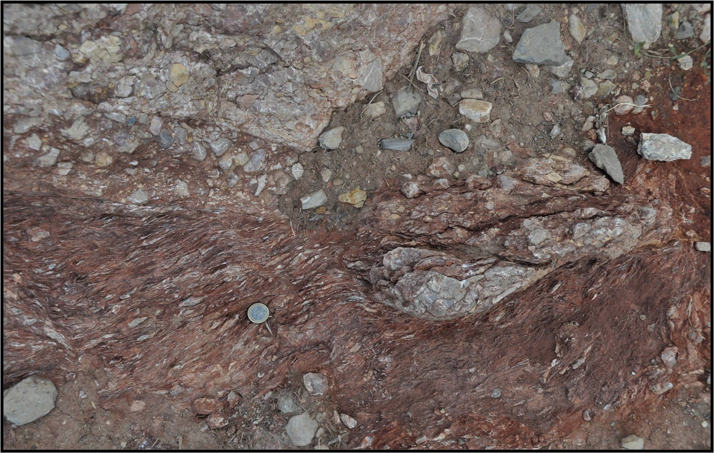
The foliation generated in a shear zone is parallel to which plane of the strain ellipsoid?
The foliation tracks the principal flattening plane (XY plane) across the shear zone Hence in shear zones formed by progressive simple shear:
the foliation is at ~45° to the shear zone walls at the margins and rotates towards parallelism with those walls in the centre of the shear zone
the stretching lineation is parallel to the maximum extension direction (X direction)
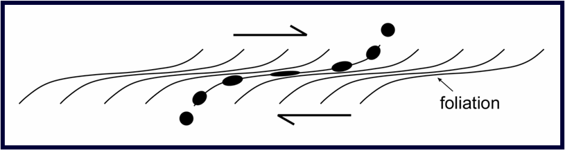
The slip direction is parallel to which axis of the strain ellipsoid?
Slip direction is parallel to the direction of principal stress
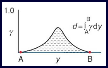
displacement = γ × shear zone width
The displacement across the shear zone is then the area under a curve of shear strain vs. distance across the shear zone normal to the shear zone walls
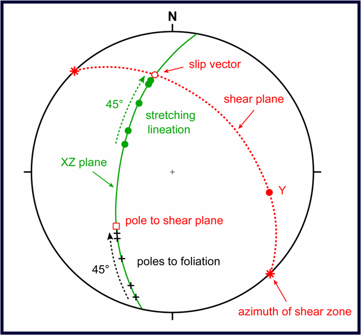
What do shear zone fabrics look like on a stereogram?
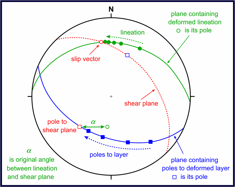
Across the shear zone, the stretching lineation (X) and poles to the foliation (Z) should be spread along the same great circle (XZ plane)
The stretching lineation should reorient towards the slip vector as one moves towards the centre of the shear zone
The pole to the foliation should reorient towards the pole of the shear plane as one moves towards the centre of the shear zone
The pole of the XZ plane (= Y) should lie in the shear plane
What do lines/planes deformed into a shear zone look like on a stereogram?
The orientations of a pre-existing lineation are spread along a great circle towards the slip vector; the intersection of this great circle with the great circle describing the shear plane is the orientation of the slip vector
The poles of a pre-existing planar feature are spread along a great circle towards the pole to the shear plane; the pole of that great circle (fold axis) lies in the shear plane
What would the direction of the arrows be for a given shape of strain ellipse?
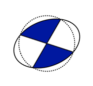
1 o’clock pointing east and 7 o’clock pointing west
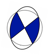
2 o’clock pointing north and 8 o’clock pointing south
What is a sheath fold?
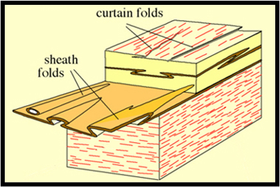
Some intrafolial folds may amplify into tubular shapes with hinge lines that swing into parallelism with the X direction as strain increases. These are described as sheath folds
Folds with hinges that are parallel with the X direction but which are not tubular are called curtain folds
Describe the following features as seen in a diagram: S-C fabrics, σ-clast, δ-clast, sigmoid, mica fish, grain shape fabric
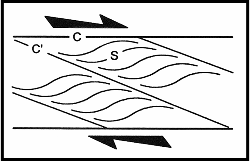
S-C Fabrics
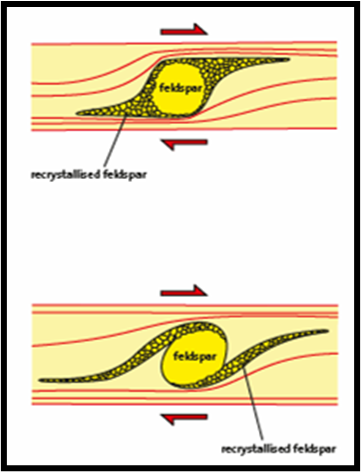
σ-clast (top), δ-clast (bottom)
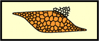
Sigmoid
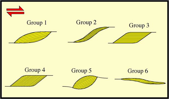
Mineral fish
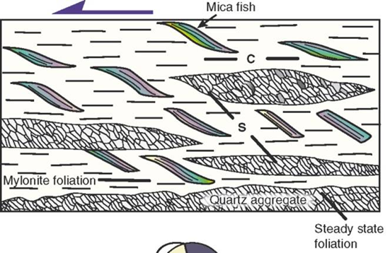
Shape fabrics
Describe the following features as seen in a sample: an en échelon array of tension gashes, pressure solution cleavage
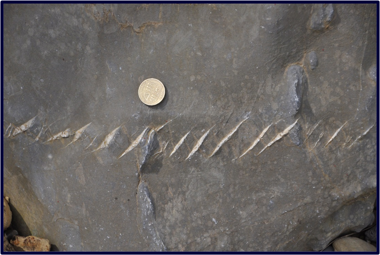
en échelon array of tension gashes
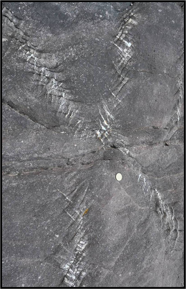
pressure solution cleavage at ~90° to the gashes
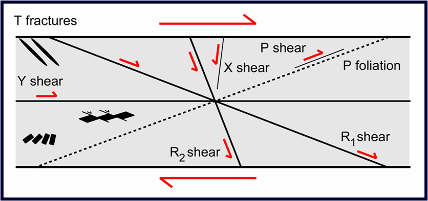
Describe the following features: P-foliation, R1 Riedel shears, Y shears
P-foliation due to the alignment of platy minerals
R1 Riedel shears with slip synthetic to shear sense
Y-shears parallel to the shear zone walls
B-shears that run along the shear zone walls
What are the units of stress in base S.I. units (kg, m, s)?
The starting point for considering stress is traction. Traction (T) is force intensity and is defined as T = F/A
The SI unit of force is the Newton (N) - the force required to accelerate 1 kg at 1 ms-2
Hence the SI unit of traction is N/m2 which is known as a Pascal (1 Pa = 1 Nm-2)
The Pascal is a small quantity – we commonly work in megaPascals (MPa), where 1 MPa = 106 Pa (NB. 1 kbar = 100 MPa)
What are the key concepts of normal and shear stress, the signs of normal and shear stresses, principal stresses and the matrix representation of stress in Mohr circle and tensor conventions?
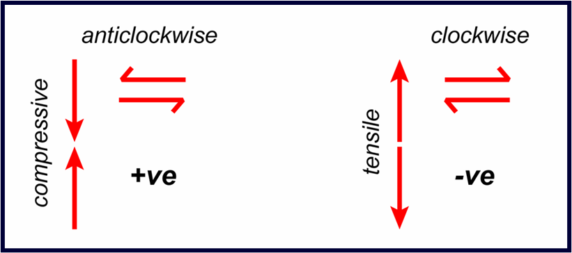
Positive tractions are defined as compressive and with an anticlockwise sense of shear
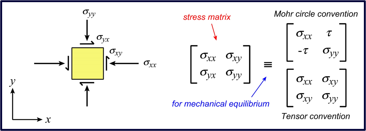
The leading diagonal of the matrix contains the normal stresses and the off-diagonal terms are the shear stresses
The state of stress is defined by four numbers:
two normal stresses, σn = σxx , σyy
two shear stresses, τ = σxy , σyx
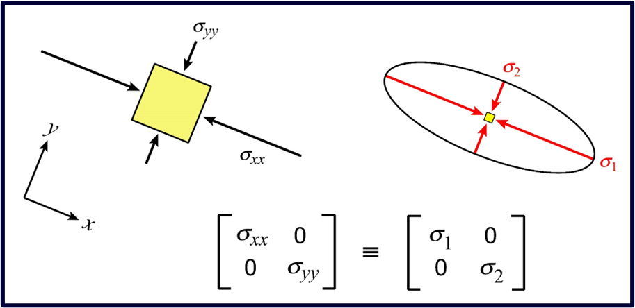
In an orientation of the coordinate axes such that the shear stresses are zero parallel to these axes, the normal stresses parallel to the coordinate axes are described as principal stresses, σ1 and σ2, where by convention, σ1 ≥ σ2
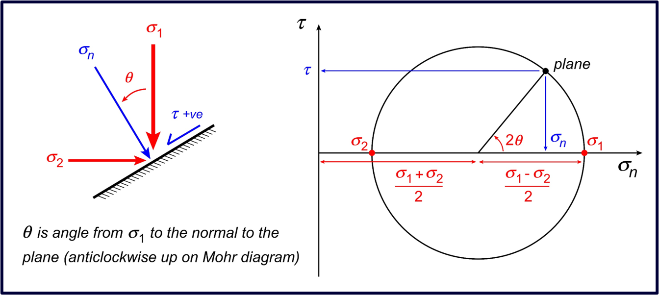
There is a straightforward graphical approach that allows the stresses on a plane of any orientation to be calculated. The diagram that implements this approach is known as the Mohr diagram
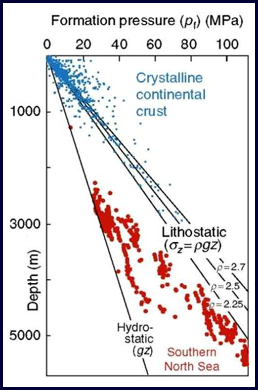
What is the formula for vertical stress, the definition of an over-pressured pore and the definition of the pore pressure parameter, λ?
The vertical stress is usually set equal to the overburden given by
σv = ρrockgz
where ρrock is the average density of the rock column to a depth of z below the surface, and g is the acceleration due to gravity
Assuming that pores are interconnected to the surface, the depth variation of pore fluid pressure is
pfluid = ρfluid g z ~ g z
If the pores are not interconnected, then the pore fluids may be over-pressured
In such cases, pore fluid pressure varies between the hydrostatic condition and the lithostatic condition but cannot be much greater
The pore pressure parameter λ ≡ pfluid/σv
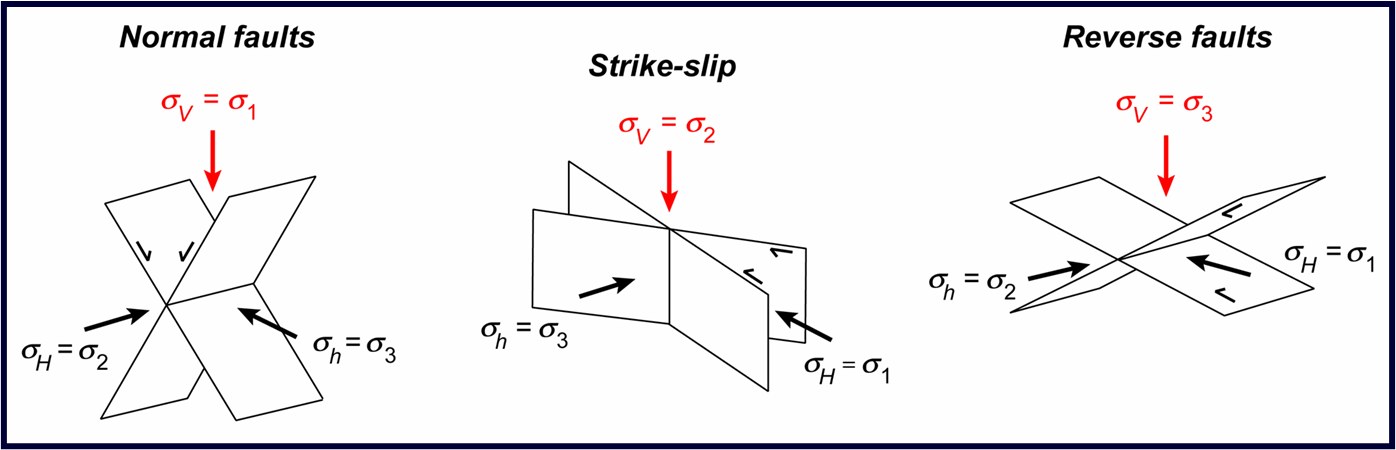
Which principal stress is vertical in areas that have active high angle normal faults, active low angle reverse faults, and active vertical strike-slip faults?
Tectonic stresses are classified into three regimes depending upon which of the three principal stresses is vertical (Andersonian classification)
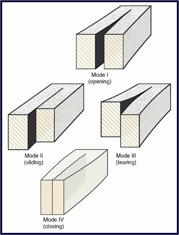
What is the distinction between an extension fracture, a shear fracture, a stylolite, and a hybrid fracture?
Fractures are classified by the displacement across the fracture surface during their formation
Extension fractures (Mode I): displacement normal to the fracture walls in an opening sense
Shear fractures (Mode II, Mode III): displacement parallel to the fracture walls – the two modes distinguish two orthogonal slip directions
Contraction fractures (Mode IV) including stylolites: displacement normal to the fracture walls in a closing sense (anticracks)
Hybrid fractures (mixed mode): fractures that are some combination of the other types (usually extension + shear OR compression + shear)
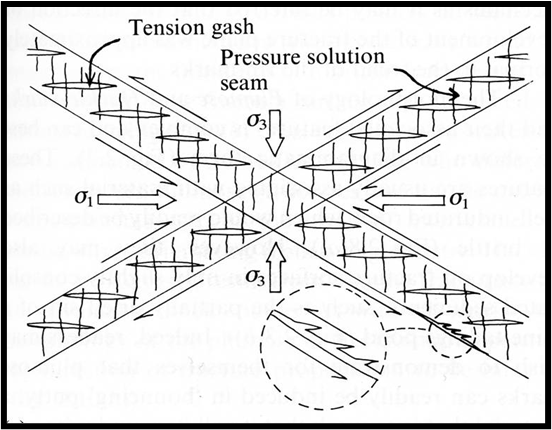
In a pair of conjugate shear fractures or tension gash array, could you indicate the orientation of σ1 and σ3, the sense of shear and the expected orientation of a pressure solution cleavage?
These arrays often come in conjugate pairs at 40° - 60° to each other
The extensional nature of the gashes, and the contractional nature of the stylolites oriented normal to them → direction of maximum compressive stress (σ1 ) bisects the acute angle between the conjugate pair and σ3 bisects the obtuse angle
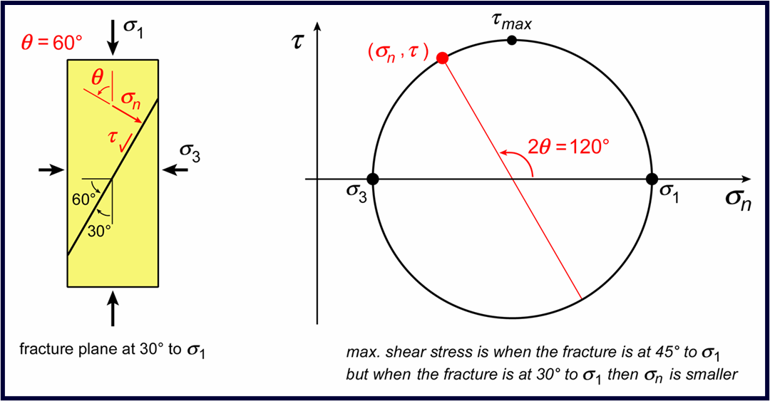
How do you calculate σn and τ on a fracture plane using a Mohr diagram?
σ1 is axial stress and σ2 = σ3 is the confining pressure, and so the normal stress and shear stress on the fracture plane may be obtained from the angle that the fracture plane makes with σ1 using a Mohr diagram
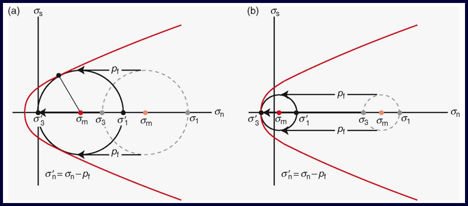
What is the effect that increasing pore fluid pressure has on the location of the Mohr circle
Pore fluid pressure acts against the normal stresses, while leaving the shear stresses unaffected → on a Mohr diagram pore fluid pressures shift the Mohr circle left without changing its diameter
Increasing pore fluid pressure leads to a shear fracture if the failure envelope is touched while the effective σ3 (= σ3 - pfluid) is still compressive or to a hybrid or extension fracture if it is touched when the effective σ3 is negative
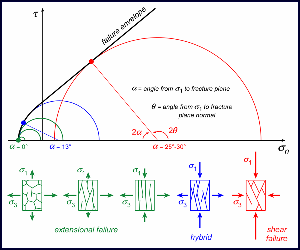
What is a failure envelope on a Mohr diagram?
Plotting the normal stress (σn) and shear stress (τ ) on the fracture plane at failure for samples deformed at different confining pressures, defines a failure envelope on a Mohr diagram
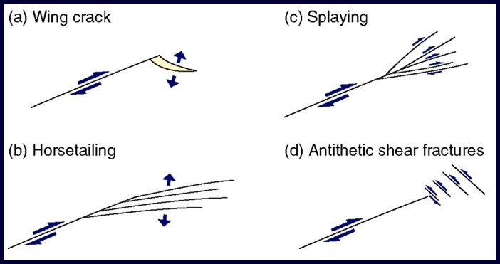
How do you infer sense of shear from wing cracks and horsetailing at the tip of a shear fracture?
Shear fractures cannot propagate in their own plane but instead propagate either by generating new extension cracks at their tips (wing cracks) or by linking up already existing extension cracks
At the terminations of shear fractures the displacement of the main fracture is distributed on many smaller fractures, arranged as synthetic shear fractures (splaying), as extension fractures on one side of the fracture (horsetailing), or as antithetic shear fractures
What is hydraulic fracturing?
Veins form when fluid pressure builds up sufficiently to generate extension fractures (hydraulic fracturing), and minerals are then precipitated out of solution – in most cases solubility decreases with decreasing fluid pressure
The force driving hydraulic fracturing during emplacement of intrusions comes from the buoyancy force of the magma
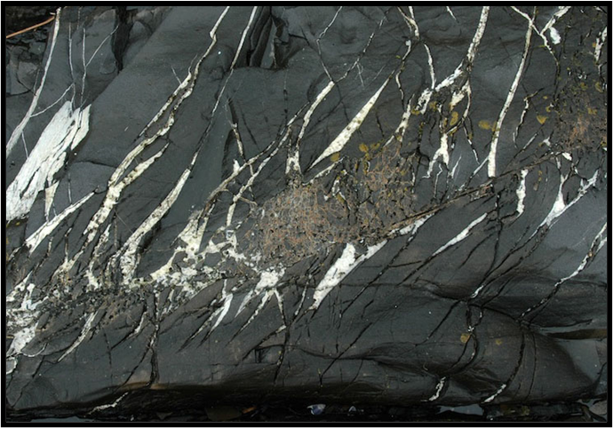
What is a listric fault and a roll-over antiform?
Faults are described by their dip: low-angle faults dip less than ~30°; high-angle faults dip more than ~60°
Listric faults flatten downwards (common); anti-listric faults steepen downwards (unusual)
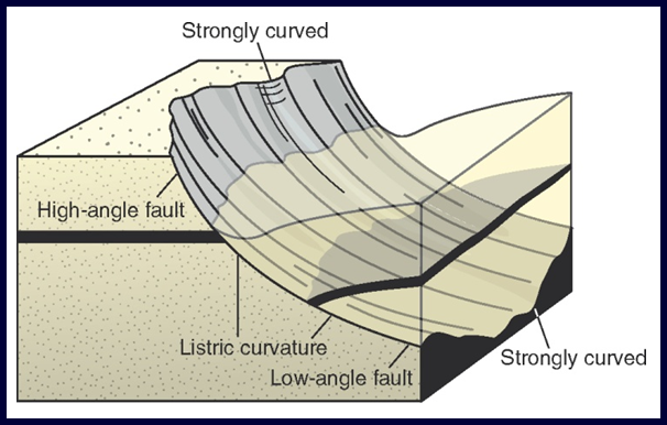
On a listric normal fault the downwardly decreasing dip commonly leads to a roll-over antiform within the hanging wall
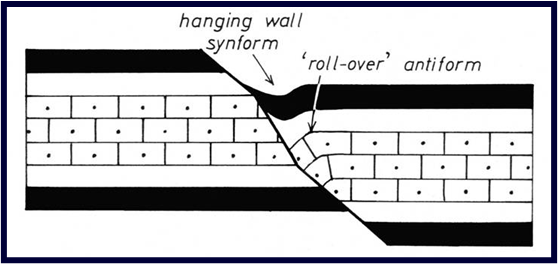
How would you indicate the sense of movement on a fault with associated drag folds?
The layering cut by faults often bends in a way that allows the movement sense to be determined. These structures are described as drag folds
•Drag folds form most easily when the cut-off lines are at a high angle to the slip vector, and so in sub-horizontal sedimentary rocks they are most commonly seen on high angle normal and reverse faults
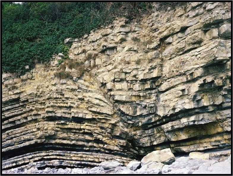
While many drag folds are breached (faulted) fault propagation folds, drag folding can also develop in the zone of interaction between two overlapping en échelon faults
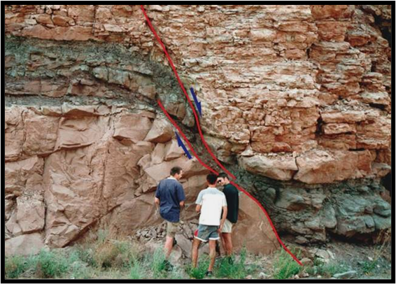
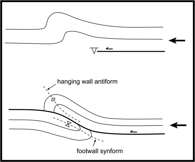
What is a fault propagation fold?
Many drag folds result from bending of layers ahead of propagating fault tips – folding precedes the passage of the fault; they are breached fault propagation folds
A hanging wall antiform – footwall synform pair may be formed when a thrust fault breaches the fault propagation fold
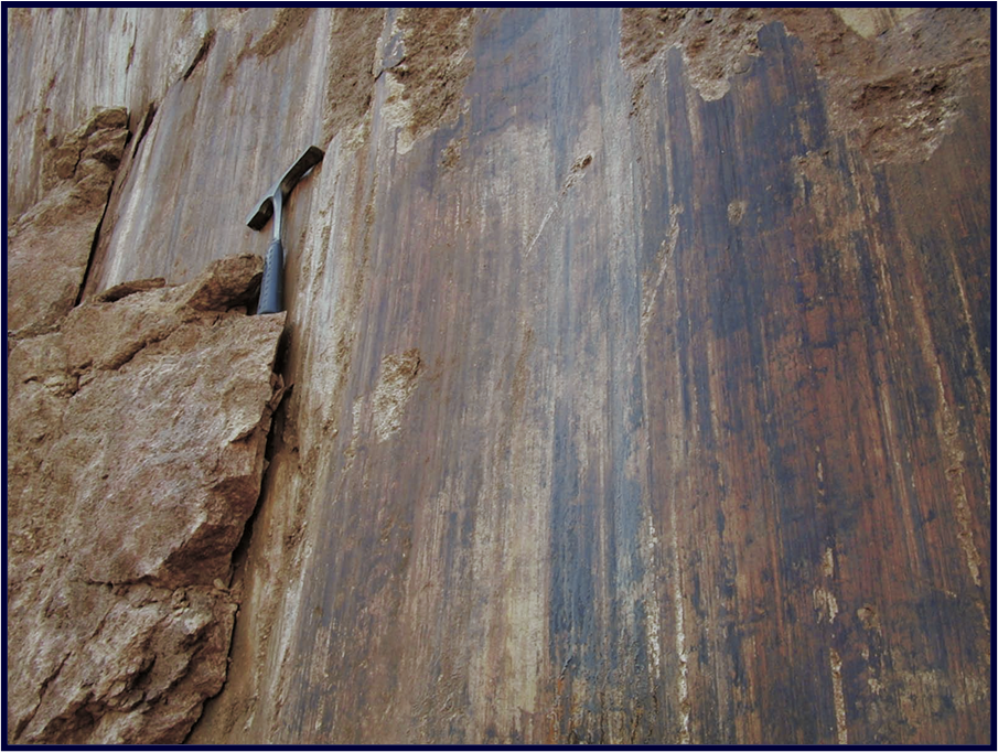
What are slickensides (sensu stricto and sensu lato)?
In response to movement, fault surfaces commonly become smooth and polished and are then described as slickensides (sensu stricto)
Fault surfaces (including slickensides), particularly where they are not perfectly planar, commonly develop three types of strongly oriented lineations, that are also described as slickensides (sensu lato)
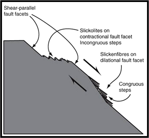
How could you work out the sense of movement from a diagram or photo of slickenfibres?
Shearing on non-planar surfaces leads to regions of compression and dilatancy
On surfaces under compression slickolites may develop, or there may be enhanced damage such as crushing and fracturing; on dilatant surfaces there may be mineral precipitation to form slickenfibres
With care such features may be used to indicate slip sense, the lineation itself providing the line of slip
Given a failure envelope on a Mohr diagram, how would you identify the cohesive strength and coefficient of internal friction?
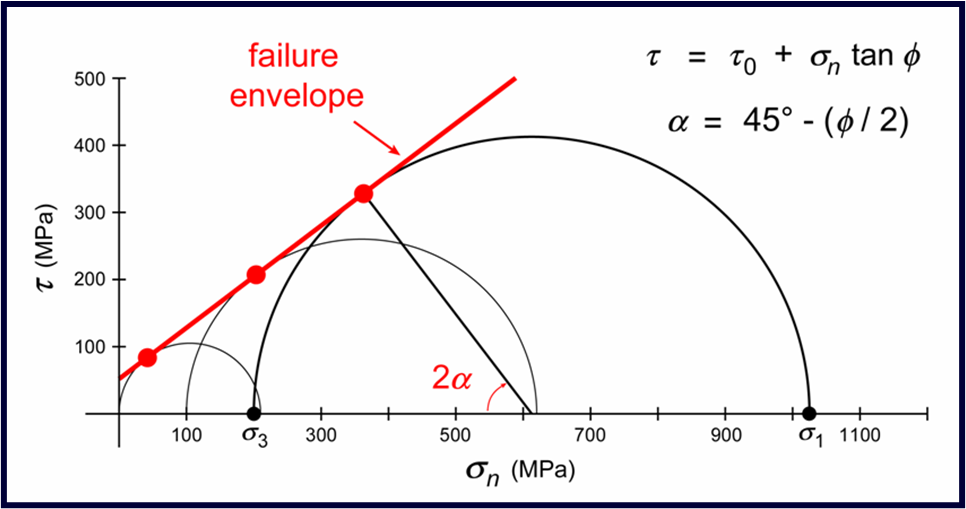
Plotting a Mohr diagram of the values of σn and τ on the fault plane at failure for each confining pressure – if the σ1 vs. σ3 plot is a straight line, so is the failure envelope on a Mohr diagram
intercept (τ0) = cohesive strength
slope (μ = tan ϕ ~ 0.6) = coefficient of internal friction
the angle (α) between the fault plane and σ1 follows from the slope and is typically ~30°
What is Byerlee’s law?
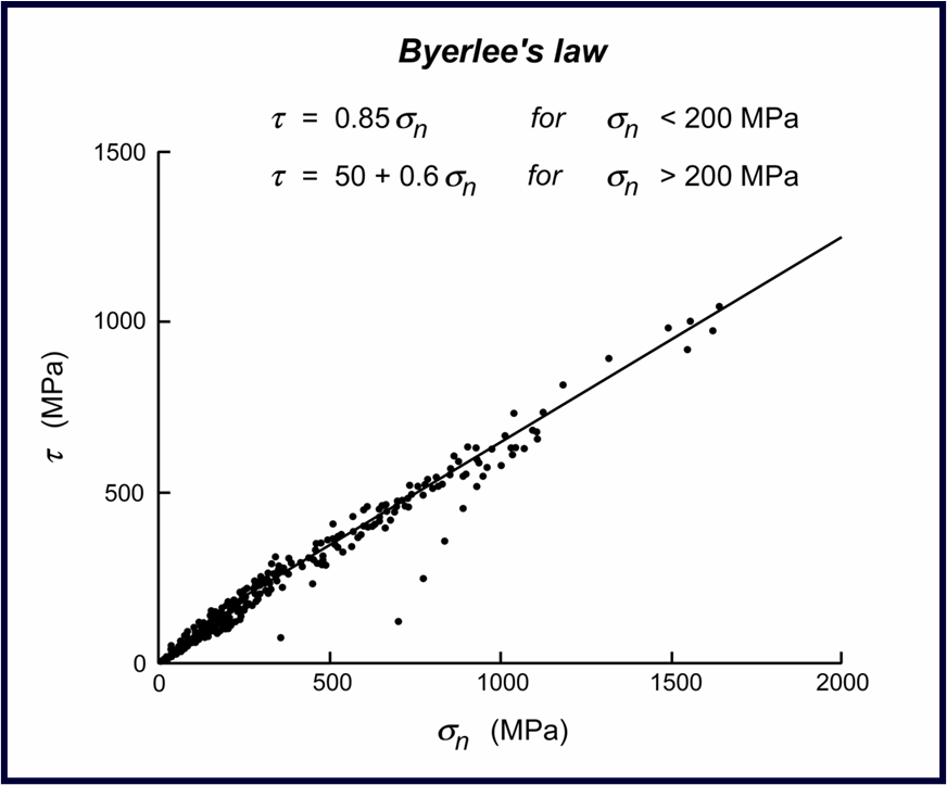
The failure envelope for frictional sliding has a similar slope (coefficient of internal friction) to that for intact rocks, but the cohesive strength (τ0) is smaller
Almost all lithologies (except those rich in sheet silicates) have a similar coefficient of frictional sliding at large stresses, μ ~ 0.6 → ϕ ~ 30°, this is Byerlee’s law
How do a set of shear fractures link up and what is a relay ramp?
As faults grow, they become more likely to interact with nearby faults. Two faults may join to form a single much longer fault. Growth in this manner gives rise to a number of important structures
Once the tips have passed each other they are said to overlap.
The zone of overlapping (relay ramp) becomes deformed as the result of displacement transfer from one fault to the other.
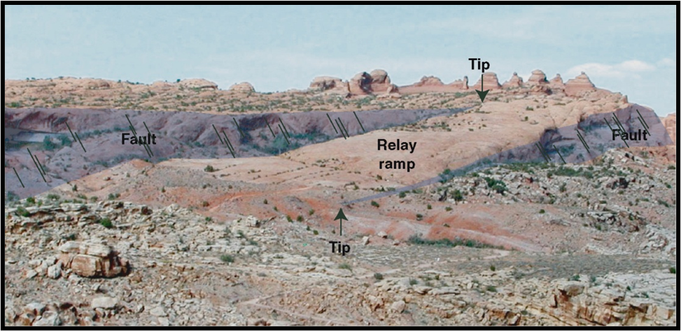
Eventually this relay structure fails (breached relay ramp) and the two faults become connected.
How would you indicate the sense of slip on the faults and identify the transfer zone as contractional or extensional from fractures in a transfer zone between two faults?
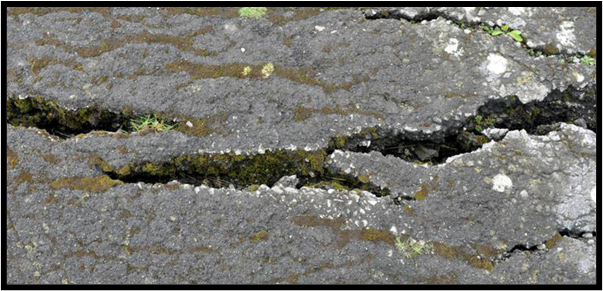
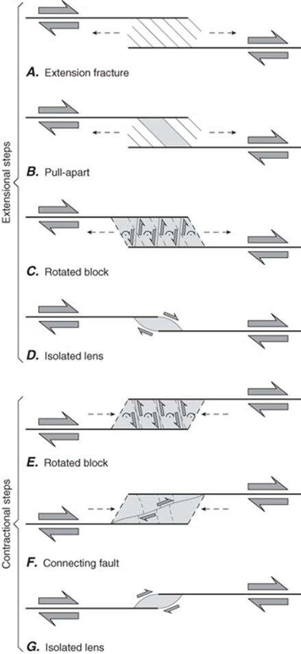
The structures that form in the zone of overlapping between two faults (transfer zone) depend upon whether the deformation there is extensional (releasing overlap zones) or contractional (restraining overlap zones)
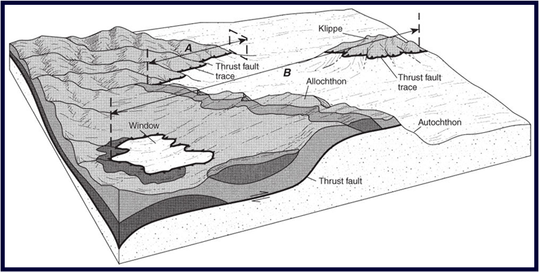
Define the following: thrust, nappe, klippe, tectonic window
A thrust is a predominantly low-angle fault or shear zone with a predominantly reverse dip-slip sense of movement
The hanging wall of a low angle, large-displacement thrust is wide compared with its thickness and so is described as a thrust nappe or thrust sheet
Erosion through a thrust sheet may mean that it is discontinuously exposed: an erosional remnant of a nappe is a klippe; an erosional hole exposing the units beneath the thrust is a (tectonic) window
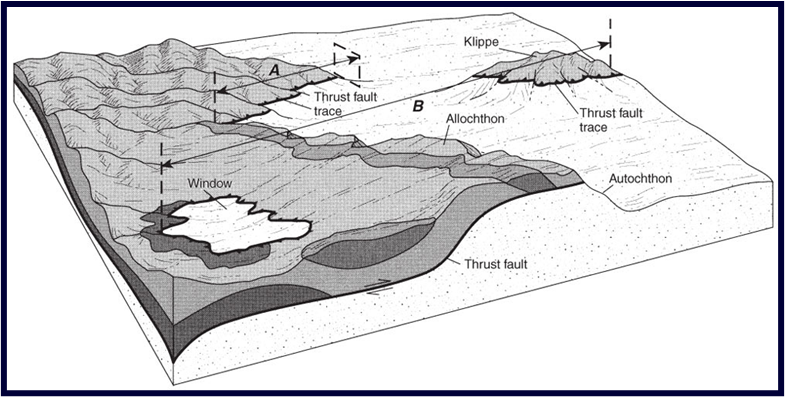
What is the distinction between autochthon, allochthon, parautochthon?
The thrust sheet is transported (allochthon);
The footwall is close to its original location (autochthon);
Slices of basement/cover caught up in the thrusting and moved relatively short distances (parautochthon)
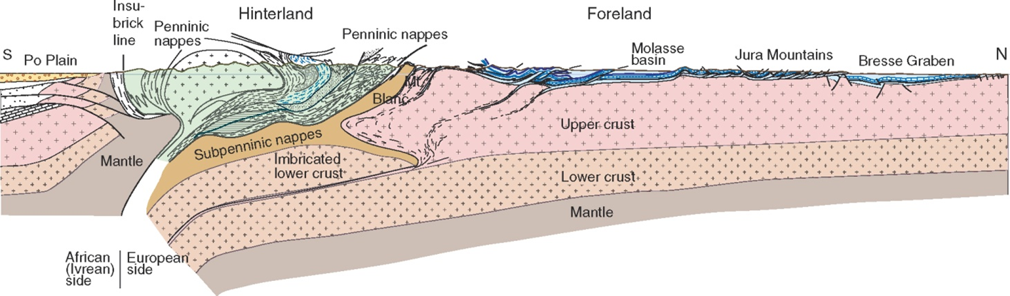
In a fold-and-thrust system, define foreland and hinterland
The bulk of the shortening in contractional orogenic belts is localized on to thrust faults
In the foreland these thrust systems are typically restricted to the cover rocks (the basement is not involved), and so the style of deformation is described as thin-skinned
In the higher metamorphic grade hinterland, the thrust systems are thicker and the basement is involved, and so this style of deformation is described as thick-skinned
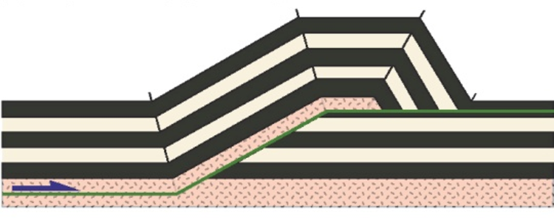
In a fold-and-thrust system, define hanging wall ramp, hanging wall flat, footwall ramp, footwall flat
A low angle thrust fault typically passes up stratigraphy in a series of steps in which it alternately follows weak horizons and cuts up section across more competent layers
Where the fault runs parallel to layering it is described as a flat; where it cross-cuts and truncates the layering it is described as a ramp
Note that the position of flats and ramps may differ on footwall and hanging wall
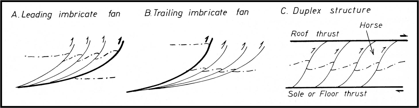
In a fold-and-thrust system, define imbricate fan, floor thrust, roof thrust, duplex, horse and basal detachment
Thrusts often come as sets of listric faults, each fault with the same sense of slip, so that the individual thrust sheets overlap like a set of roofing tiles. This situation is described as an imbricate fan. Leading imbricate fans have maximum slip on the frontal fault; trailing imbricate fans have maximum slip on the most internal fault
Imbricate faults merge down on to a sole or floor thrust.
They may also merge up on to a roof thrust.
An imbricate system that is bounded by a floor and a roof thrust is known as a duplex, and the internal blocks (which are bounded completely by faults) as horses
The major floor thrust at the base of a stack of thrust nappes and/or imbricate system is described as a décollement or basal detachment
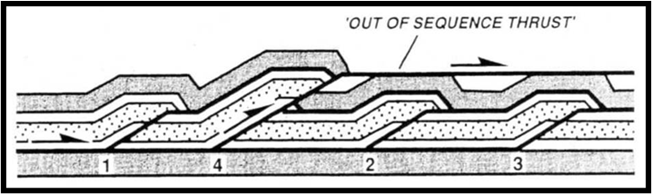
In a fold-and-thrust system, define out-of-sequence thrust and antiformal stack,
Although thrusts usually propagate towards the foreland, it is not uncommon for an out-of-sequence thrust to develop at a position behind the thrust front
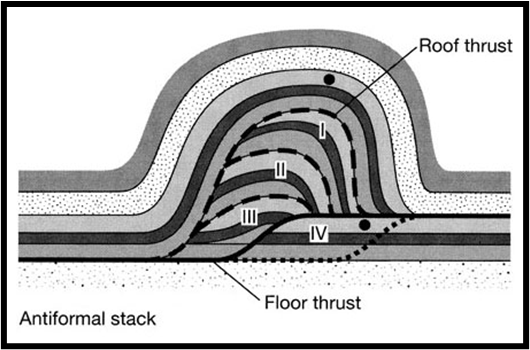
When there is greater drive on the roof thrust than on the floor thrust, foreland-propagating thrust duplexes develop such that the horses are stacked, resulting in an antiform in the overlying thrust sheet
Such structures are described as antiformal stacks
In a fold-and-thrust system, define branch point and cut-off point
No cross section though a thrust system should be constructed without considering how the individual faults link up to form three dimensional networks of faults
Tip-lines: the line marking where fault displacement dies out
Branch-lines: the line marking where a fault splits in two (trailing branch-line) or where two faults merge (leading branch-line)
Cut-off lines: the line marking the intersection of some contact with the fault surface
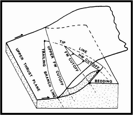
In a fold-and-thrust system, define back thrust, pop-up and triangle zone.
As thrust sheets climb over ramps, thrusts with the opposite vergence may form (effectively in the conjugate fault orientation). These are back-thrusts
Combinations of thrusts and back-thrusts with the same floor thrust delimit pop-ups and triangle zones
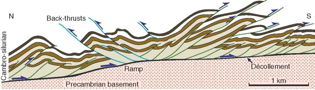
What is a foreland propagating thrust system, and a break-back thrust sequence?
Thrust duplexes form sequentially, usually propagating towards the foreland: a horse is formed in the footwall, is displaced forwards, and becomes inactive; a new horse is then formed in the footwall
The ramps bounding the horses dip towards the hinterland
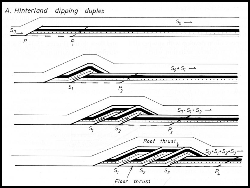
Less commonly, the horses nucleate in the hanging wall so that they propagate towards the hinterland. This is described as a break-back sequence
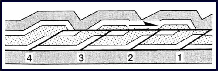
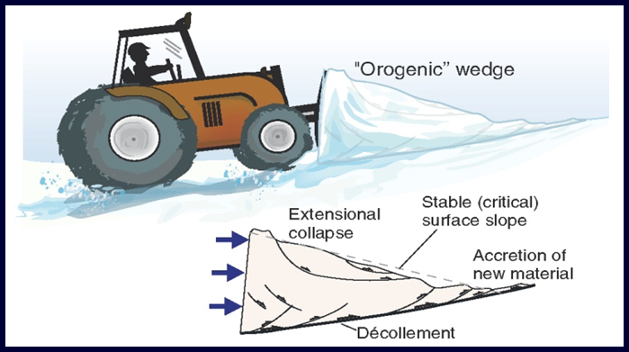
For a thrust wedge at critical taper, what happens if the wedge is thickened by a push directed towards the foreland from the hinterland, and the wedge is thinned by erosion?
Fold and thrust belts show an overall wedge-shaped geometry in cross-section, thinning towards the foreland. Mechanically, such a wedge deforms until it reaches a constant critical taper
As the wedge thickens, the surface slope increases but so does the basal slope because the weight of the wedge depresses the lithosphere. The wedge adjusts either by lengthening, or by thinning
As the wedge thins, the surface slope is maintained by uplift through internal shortening
What is the definition of an extensional fault?
A fault is described as extensional if it leads to elongation perpendicular to the strike of the fault.
Hence faults with a normal component of dip-slip displacement are extensional
This definition takes the surface of the Earth as reference. If instead we were to define an extensional fault as one that lengthens a given layer, then in certain scenarios reverse faults can be extensional
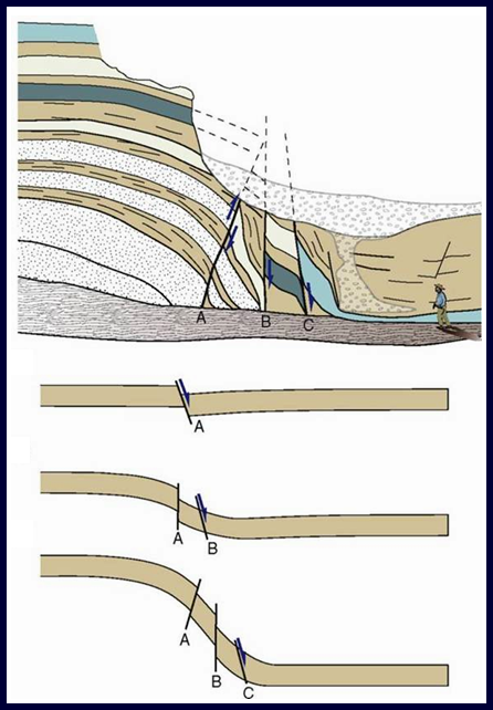
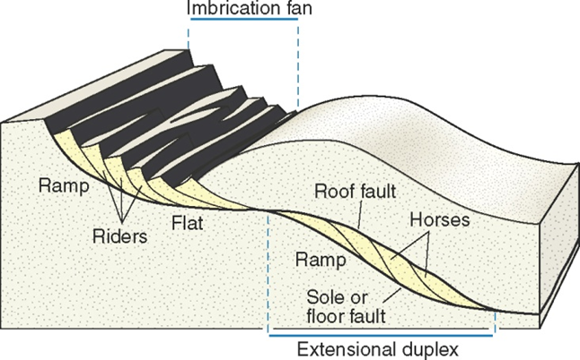
In extensional faulting, define an extensional imbricate fan and extensional duplex
Sets of listric extensional faults that merge down into a detachment form extensional imbricate fans; if they also merge upwards into an extensional roof fault, they form an extensional duplex
The term horse applies for the fault bound blocks within a duplex; the term rider is used for the fault blocks in an imbricate fan
In extensional faulting, define a detachment
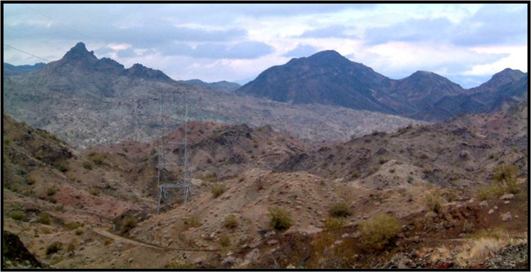
Extensional faults exist with lengths and displacements of millimetres through to those in metamorphic core complexes that are on the scale of mountain ranges with displacements of up to ~ 100 km
Those with large displacements are gently dipping and are described as detachments
In extensional faulting, define a graben, horst and half-graben
A graben is a downthrown block bounded on each side by conjugate normal faults that each dip towards the downthrown block
A horst is a relatively uplifted block bounded by two conjugate normal faults that each dip away from the uplifted block
A half-graben is a downthrown and tilted block bounded on only one side by a major normal fault
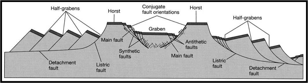
In extensional faulting, define an antithetic fault and synthetic fault
Commonly, in extensional fault systems significant displacement occurs on smaller scale faults within the hanging wall of the main fault
If the smaller faults are ~ parallel to the main fault and have the same sense of shear, they are synthetic faults
If they are in the conjugate orientation, they are antithetic faults
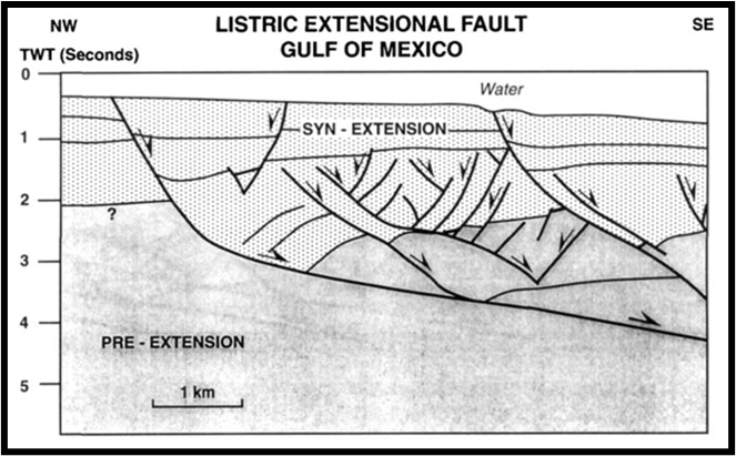
In extensional faulting, define a rollover antiform
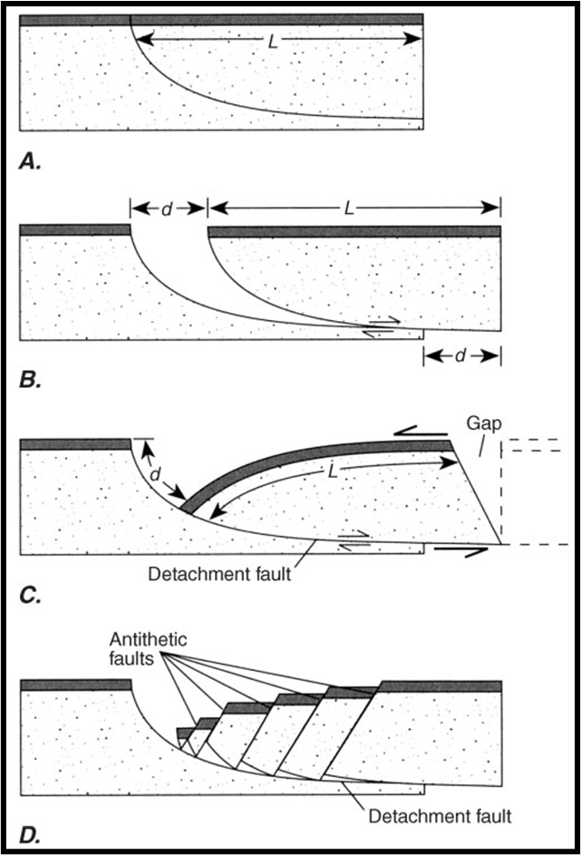
Extension on listric faults must be accompanied by significant hanging wall deformation to resolve the space problems. Rigid displacement of the hanging wall of a listric fault opens a large gap
If the bottom edge of the hanging wall is forced to conform to the shape of the fault, while keeping layer length constant, the resulting geometry is a rollover antiform.
What are the three phases of rift development?
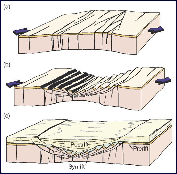
Rifting occurs in three phases
Initial phase: rifting as a result of large-scale crustal doming; steep fracture systems form; possible intrusion of magma generated at depth
Main stretching phase: formation of major faults/fault blocks that accommodate the crustal thinning
Late subsidence phase: cooling and basin deepening once stretching has ceased; fault movement is mostly limited to that induced by differential compaction of the sedimentary succession
Why does a continent-continent orogenic collision commonly end with extensional collapse of the orogenic belt?
While an ocean still exists between two converging continents, extension occurs by back-arc rifting and also in the outer arc of the oceanic plate where it bends on entering the subduction zone
Normal faults may form in the orogenic wedge if it is over-thickened by incorporation of a basement slice
A detached and heated basement slice may be buoyant enough to ascend, bounded by a thrust on its lower side and by a normal fault on its upper side (channel flow)
Heating of thickened crust may lead to sufficient weakening for it to collapse under its own weight (gravitational orogenic collapse)
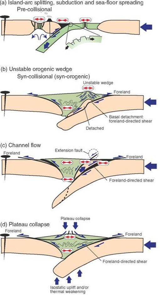
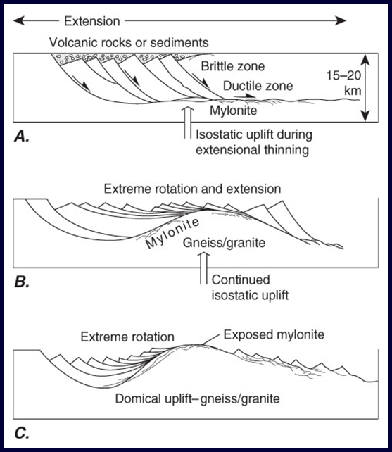
What is a metamorphic core complex?
During extreme extension (100%+), thinning and isostatic compensation elevates deeper levels of the crust. Eventually, the high-grade footwall rocks may be exposed at the Earth’s surface
These are metamorphic core complexes
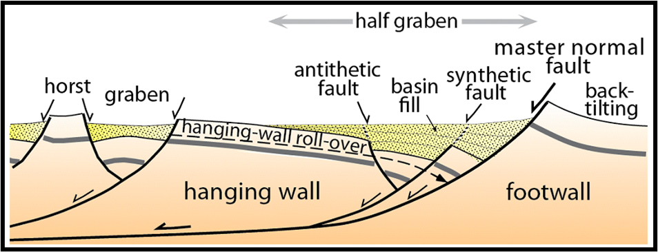
What geometry do sedimentary units have within a half-graben if slip on the fault is occurring at the same time as the sedimentation?
Sedimentary infills in half-grabens – if deposited while movement on the fault was ongoing (growth fault) these infills thicken towards the fault
The geometry of the wedge-shaped units within half-grabens may be used to reconstruct the shape of the underlying fault
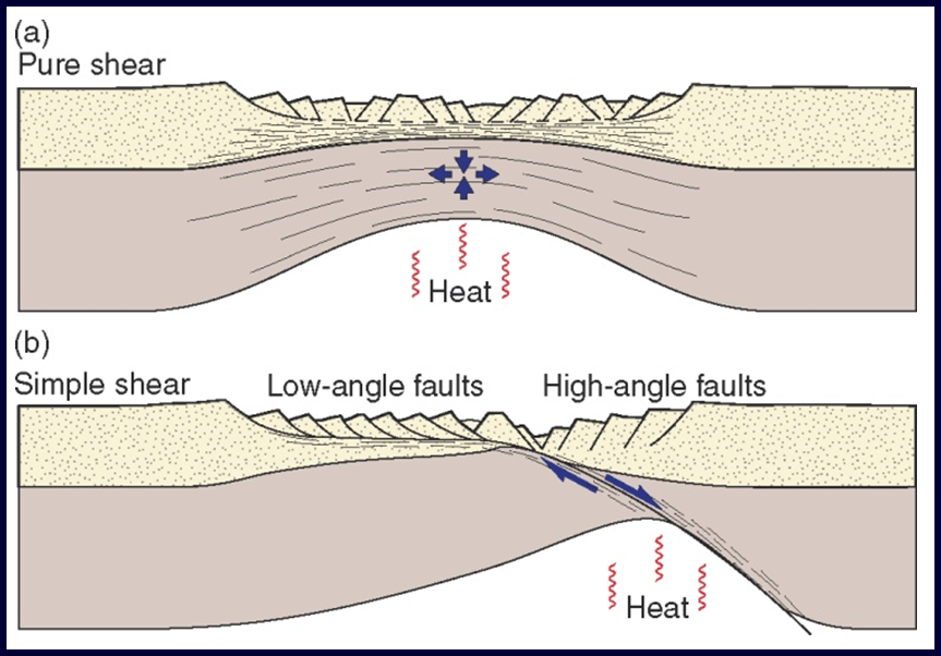
What is the distinction between pure shear and simple shear models of lithospheric extension?
In the pure shear model the highest geothermal gradient is under the centre of the region of extension; in the simple shear model it is offset to one side.
Pure shear: the overall deformation across the region of extension creates symmetric thinning of the lithosphere, accommodated by brittle faulting in the upper crust and plastic deformation at greater depth
Simple shear: extension is localized on to a dipping shear zone that transects the lithosphere
Why are major strike-slip faults commonly straight lines on geological maps?
Strike-slip faults are faults with a slip vector that is parallel with the strike of the fault, and therefore parallel with the surface of the Earth
Most large-scale strike-slip faults are approximately vertical and so on maps they appear as straight lines.
However, locally they curve and these geometrical irregularities generate a range of structures that are economically significant
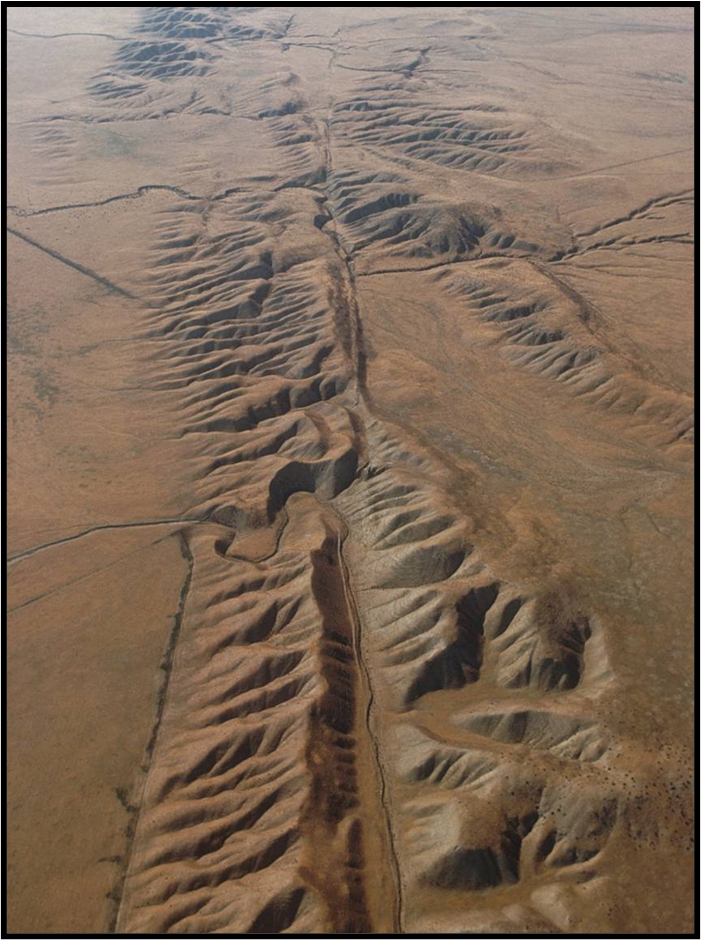
What is a transfer fault? Use your definition to explain why transform faults are transfer faults and transcurrent faults are not.
A key criterion of distinction is the notion of slip transfer
Transfer faults are strike-slip faults with tips that terminate against other faults and which serve to transfer displacement from one fault to another
A transform fault is a strike-slip transfer fault that cuts right through the lithosphere. Transform faults are always parallel with the plate motion direction
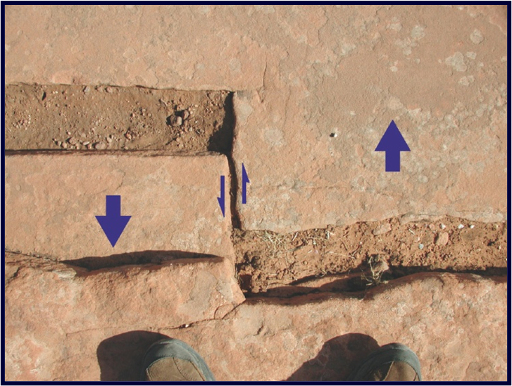
•Transcurrent faults are not transfer faults but rather they have free tips and so increase in length as the displacement accumulates
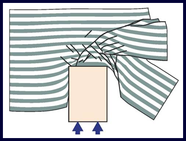
What is a stretching fault?
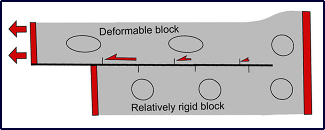
When one side of a fault is more deformable than the other, the fault marks the boundary between relatively strongly deformed units and relatively undeformed units and we have a stretching fault → slip-parallel stretching of one side of the fault with respect to the other
On a stretching fault the slip is zero at the fault tip and varies along the fault
In a strike-slip fault zone, how would you indicate the sense of shear of R and R´ Riedel shears?
Two sets of shear fractures (R and R´) develop oblique to the fault margins. These are now known as Riedel shears and may be rationalized as a conjugate fracture set about the direction of the maximum compressive principal stress.
Of these two sets, the R-shears are the ones that develop more frequently
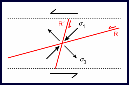
In a strike-slip fault zone, how would you indicate the sense of shear of en échelon fold axial traces?
In strike-slip terrains second order strike-slip faults may serve to transfer displacement between en échelon first order strike-slip faults. These transfer faults may develop into strike-slip duplexes
Analogue experiments with clay show that an en échelon array of simple folds forms early in the shearing and that these may later become dissected by Riedel shears
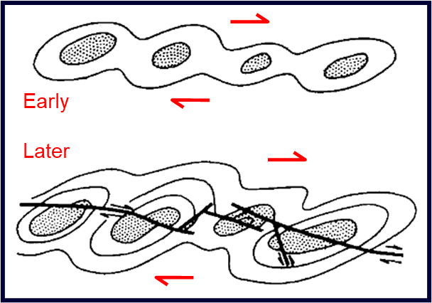
How would you identify a strike-slip fault bend or a strike-slip fault stepover as ‘releasing’ (= extensional) or ‘restraining’ (= contractional) and the expected orientation of faults across a releasing stepover and a restraining stepover?
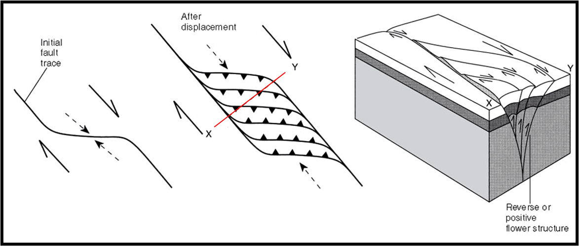
Although strike-slip faults are characteristically straight, they do contain bends (curved parts of a continuous fault trace connecting two parallel segments) and stepovers (overlapping en échelon fault segments)
A bend or stepover is restraining if the rocks at the bend/stepover are compressed during slip on the fault, and releasing if they are pulled apart
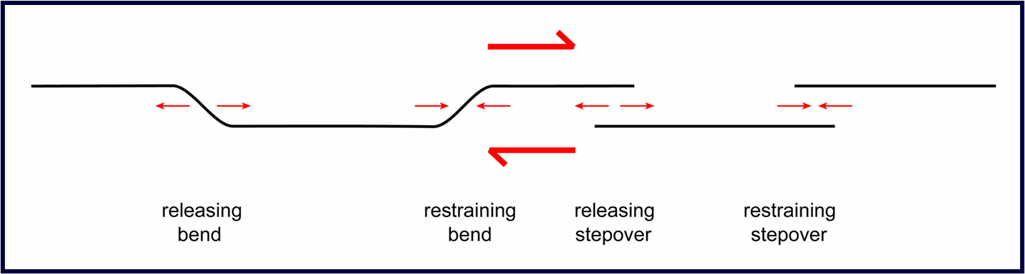
Slip at releasing bends and stepovers leads to extension fractures and, at larger scale, normal faults that may be arranged to form an extensional duplex
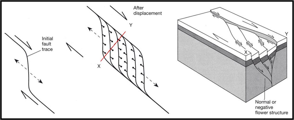
•Slip at restraining bends and stepovers leads to contractional structures (stylolites, cleavages, folds, reverse faults) and sometimes contractional duplexes
How would you indicate the sense of slip on a fault of an imbricate fan at the end of a transcurrent fault, with an indication of whether the faults in the fan were extensional or contractional,
Strike-slip faults may terminate in an imbricate fan of either normal faults or reverse faults depending upon the location of the zone of deformation relative to the fault slip vector
Alternatively, the faults may terminate as a splay of small strike-slip faults – the displacement on any individual splay fault is small but the sum equals the main fault displacement
Extensional (releasing) imbricate fan:
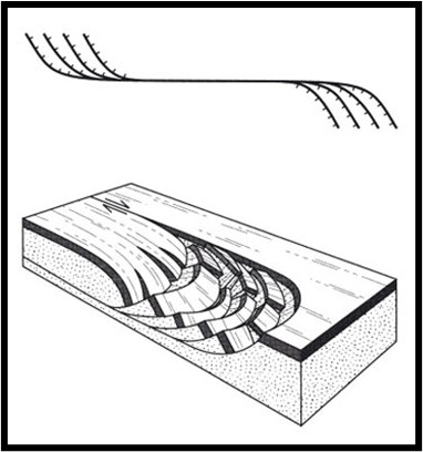
Contractional (restraining) imbricate fan: