XRAY 200 WEEK 3
 Call Kai
 Learn
 Practice Test
 Spaced Repetition
 Match
 Flashcards
 Knowt Play
1/28

There's no tags or description
Looks like no tags are added yet.
29 Terms
Panoramic image
Shows a wide view of the upper and lower jaws
extraoral tech = outside mouth

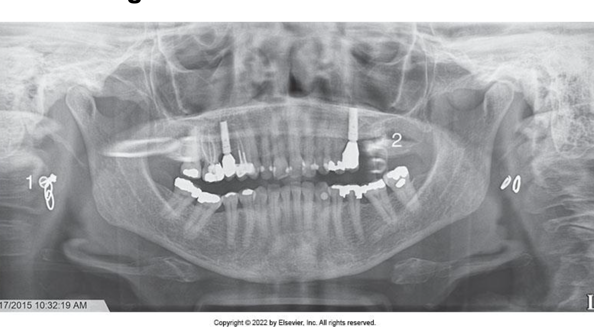
Ghost Image
metal not removed
Problem
◦ If all metallic or radiodense objects are not removed before exposure, a ghost image results that obscure diagnostic information
Solution
◦ The dental radiographer must instruct the patient to remove all radiodense objects in the head and neck
region prior to positioning the patient
Lead apron artifacat
• Problem
◦ A radiopaque cone-shaped artifact that obscures diagnostic information results if the lead apron is incorrectly placed, or if a lead apron with a thyroid
collar is used (hoodies, spine straight stand tall)
Solution
◦ The dental radiographer must always use a lead
apron without a thyroid collar when exposing a
panoramic projection

Preperation errors
ghost image
lead apron artifact
Positioning of the lips and tongue
• Problem
◦ If the patient’s lips are not closed on the bite-block during the exposure of a panoramic projection, a dark radiolucent shadow results that obscures the
anterior teeth
◦ If the tongue is not in contact with the palate during exposure of a panoramic projection, a dark radiolucent shadow results that obscures the apices of the maxillary teeth
• Solution
◦ Instruct the patient to close the lips around the bite- block and swallow and raise the tongue up to the palate during the exposure of the receptor (tongue should be at the roof of your mouth)

Chin Tipped Up
• Problem
◦ If the patient’s chin is positioned too high a “reverse smile line” is apparent on the image
• Solution
◦ Position the patient so the Frankfort plane is parallel with the floor

Chin Tipped Down
• Problem
◦ If the patient’s chin is positioned too low or is tipped down an “exaggerated smile line” is apparent on the image
• Solution
◦ Position the patient so that the Frankfort plane is parallel with the floor
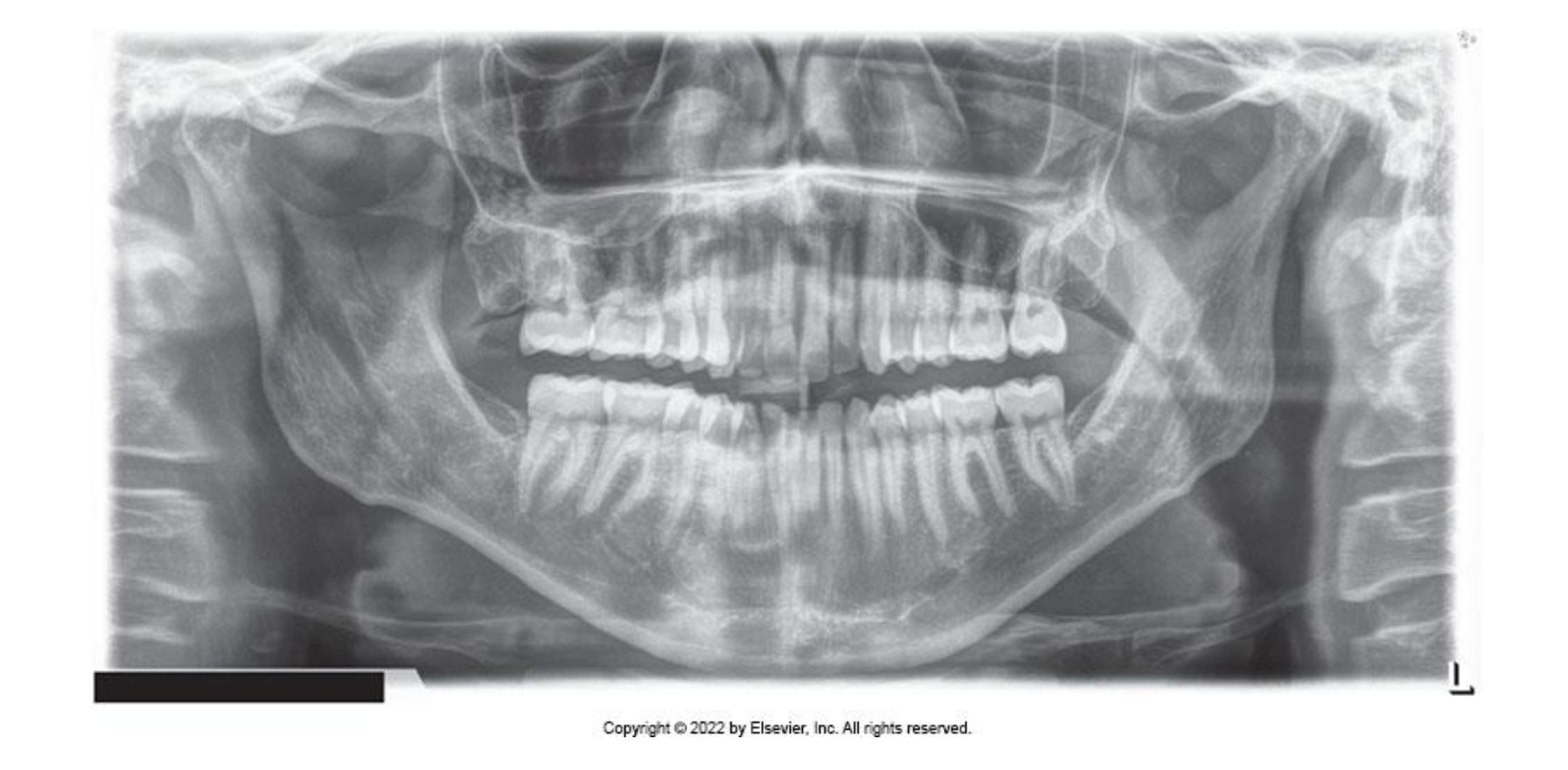
Teeth Anterior to the Focal Trough
• Problem
◦ If the patient’s teeth are positioned too far forward
on the bite-block or anterior to the focal trough, the
anterior teeth appear “skinny” and out of focus
• Solution
◦ Position the patient so that the anterior teeth are
placed in an end-to-end position in the groove on
the bite-block
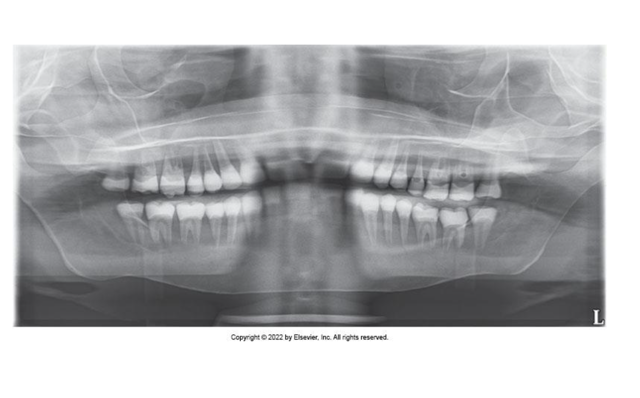
Teeth Posterior to the Focal Trough
Problem
◦ If the patient’s teeth are positioned too far back on
the bite-block or posterior to the focal trough, the
anterior teeth appear “fat” and out of focus
• Solution
◦ Position the patient so that the anterior teeth are
placed in an end-to-end position in the groove on
the bite-block
Head Turned
Problem
◦ If the patient’s head is not centered, the ramus and
posterior teeth appear unequally magnified on the
panoramic image
▪ The side farthest from the receptor appears magnified
• Solution
◦ Position the patient’s head so that the midsagittal plane is
perpendicular to the floor while the midline is centered on
the bite-block

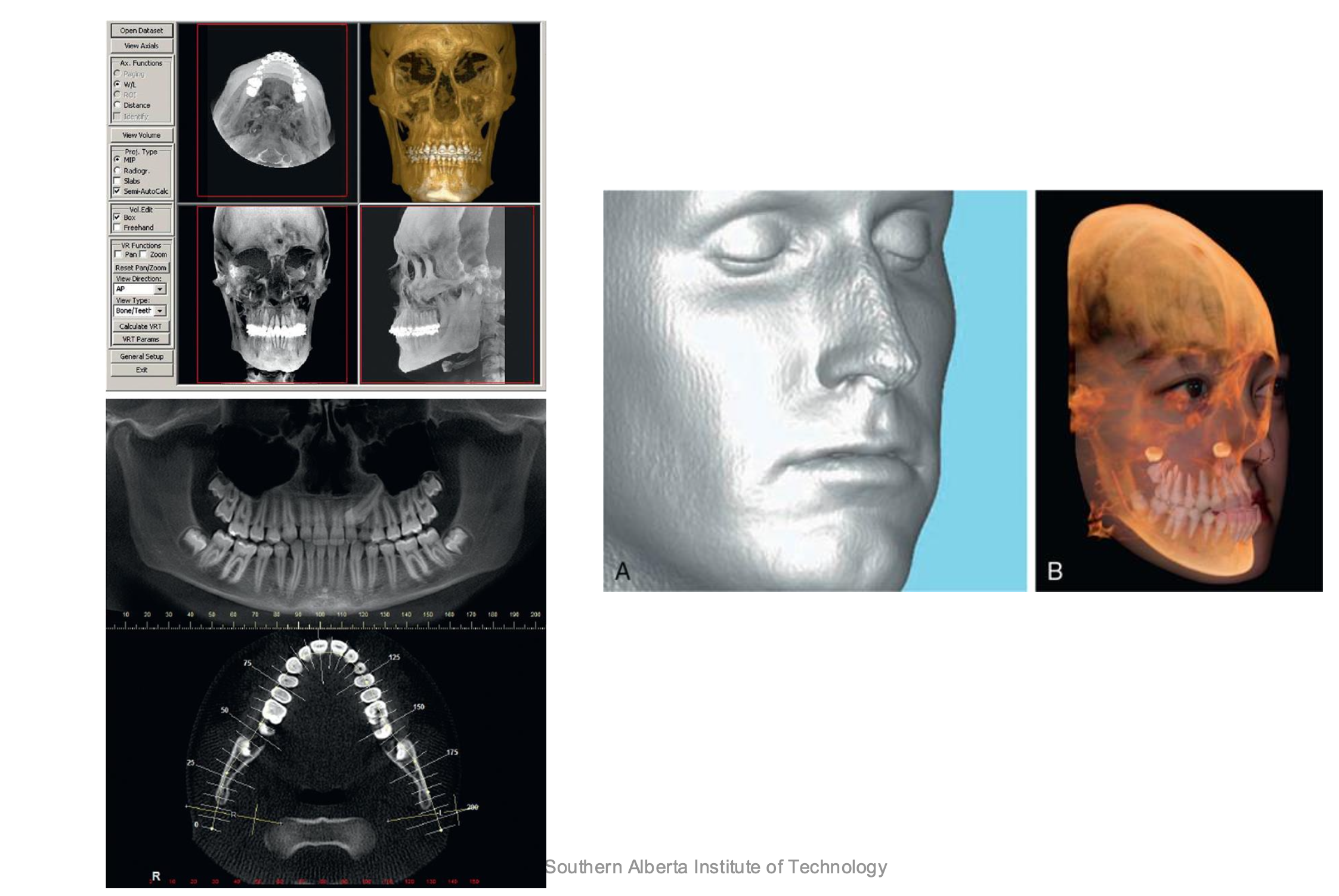
CBCT
Cone Beam Computed Tomography
Allows the viewing of the head and neck in 3 dimensions
How CBCT works
rotates around patients head
takes 200-600 images
snips them together to create a 3d image
1CBCT = 3-4 FMS
takes between 7-30 seconds to expose
CBCT Advantages
doesn’t provide info about buccal or lingual width or locations
cannot distinguish between types of soft tissues
Vital for
Exact placement of implants
buccal/lingual placement of impacted teeth
determine location of mandibular nerve before surgery
Digital radiography
Digital imaging eliminates chemical processing and hazardous wastes (lead foil, chemicals)
• Requires LESS Radiation to expose
• Allows for digital enhancements, measurements and corrections
• Images can be electronically transferred to other health care providers
• Sensors are VERY expensive
Direct digital
Solid-state sensor that contains an x-ray sensitive silicon chip with an electronic circuit embedded in the silicon
Indirect Digital
PSP (phosphor storage imaging)
Thin, flexible plate that is covered in phosphor crystals
• Plates are the same size as conventional
x-ray film
• Phosphor layer stores energy of x-ray
photons
• After exposure plates are placed into a scanner
• Scanner laser reads the latent image and converts it to a digital
image
• Films are exposed to a bright light to ”erase” the image
Intraoral Radiography
There are three different types of intra-oral radiographs, that can be taken to asses the patients dentition (inside mouth)
Periapical (PA)
shows entire tooth including root (entire tooth form occlusal surface or incisal edge)
looks for disease in root
Biitewing (BW)
shows in between the teeth
shows top and bottom teeth, no roots
look for decay in between teeth
looking for bone height
Occlusal x ray
tooth development
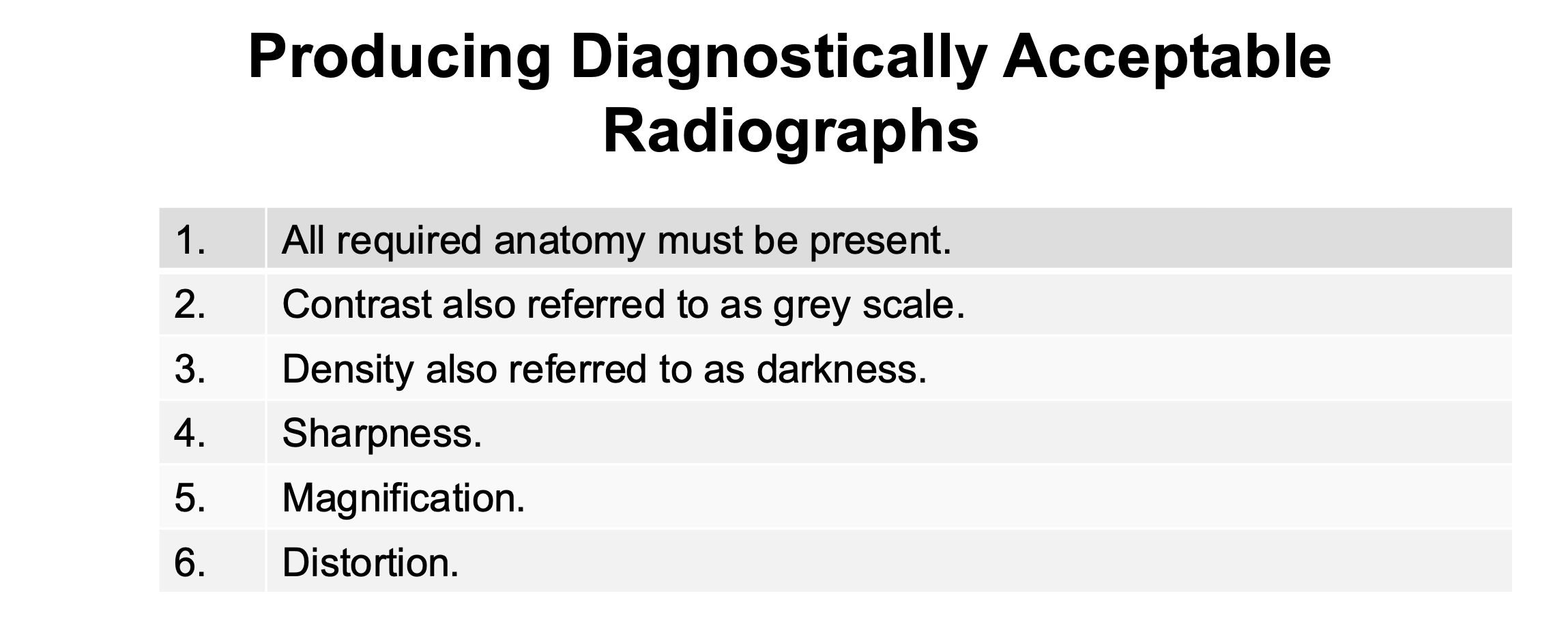
Producing Diagnostically Acceptable Radiographs
Periapical Terminology

Long Axis of Tooth
An imaginary line that divides the tooth longitudinally into two equal halves.
cut in half
Central Ray
The central portion of the primary beam of radiation
The Paralleling Technique
• Receptor is parallel to long axis of tooth
• X-ray beam is perpendicular to the long axis of the
tooth
• Face of cone is parallel with the face of the film.
• Common errors:
incorrect placement and alignment.
Paralleling Technique Steps

Advantages and Disadvantages of the paralleling technique

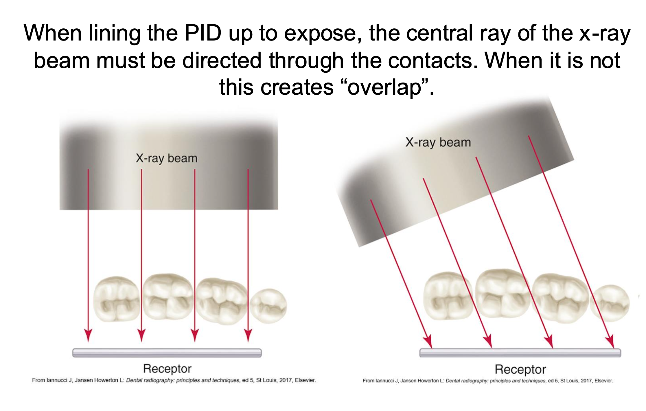
x ray beams

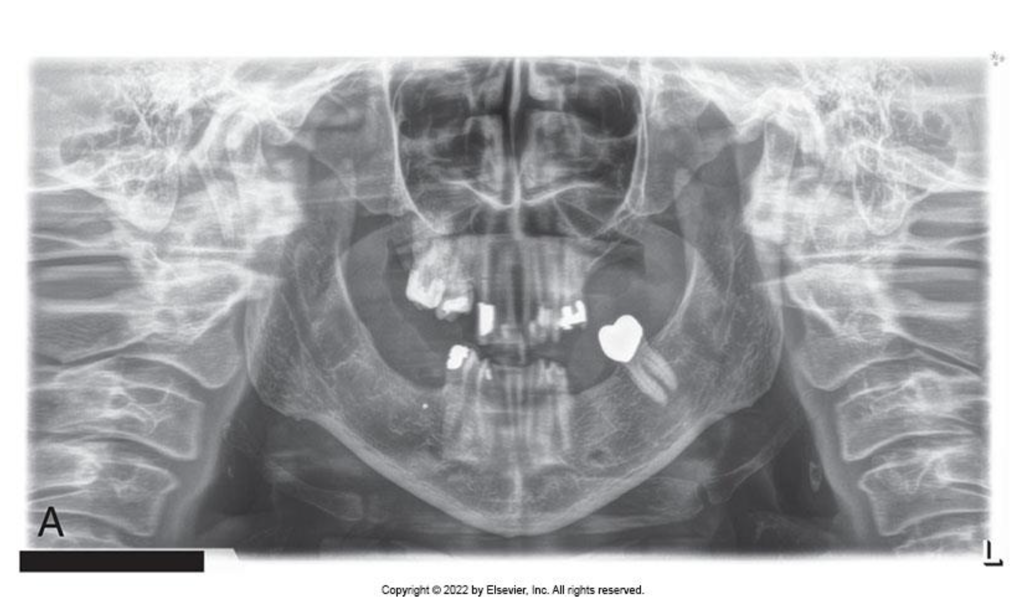
Slumped Posture
Problem
◦ If the patient is not standing or sitting with a straight spine, the cervical spine appears as a radiopacity in the center of the receptor and obscures
diagnostic information
• Solution
Instruct the patient to stand or sit “as tall as possible” with a straight back