Engine
 Call Kai
 Learn
 Practice Test
 Spaced Repetition
 Match
 Flashcards
 Knowt Play
1/26

There's no tags or description
Looks like no tags are added yet.
27 Terms
Engine Operating Limitations
Inflight Reverse Thrust→❌PROHIBITED
Engine Ignition (Flameout Protection)– Must be ON ✅ during:
Takeoff
Landing
Operations in heavy rain 🌧(protect againts water ingestion)
Anti-ice operation ❄
Reduced takeoff thrust using Assumed Temp. T/O→❌ NOT permitted with Anti-skid: (prevents wheel locking) INOP
Quick Memory 🧠
Operating rules:
Reverse Thrust → Inflight ❌
Ignition✅→ T/O + Landing + Heavy Rain + Anti-ice
Assumed Temperature + Anti-skid INOP → ❌
Engine Limit Display Markings
🔴 RED | Maximum / Minimum limits |
🟠 AMBER | Caution |
🟢 GREEN (or)⚪ WHITE | Normal (Current value0 |
Engine Specifications
2 Engines: CFM56-7B26→Dual-Rotor, Axial-Flow Turbofan
Engine Power Rating: 26K – 24K – 22K.
Compressor & Turbine
Component | Stages | Configuration |
|---|---|---|
Compressor | 12 | Fan + 3 LPC + 9 HPC |
Turbine | 5 | 1 HPT + 4 LPT |
High Bypass Ratio: 5.1
Quick Memory 🧠
Engine numbers:
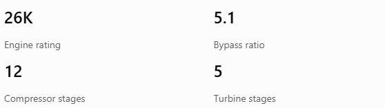
26K Engine rating
5.1 Bypass ratio
12 Compressor stages
5 Turbine stages
Compressor: Fan + 3 LPC + 9 HPC.
Turbine: 1 HPT + 4 LPT.
Accessory Gearbox
Mounted On & Driven by→N2.
5 Driven accessories:
IDG (Integrated Drive Generator)
Bleed Air Starter→powered by→Bleed air→Disingaged: Starter Cutout Speed
EDP (Engine Driven Pump)
Engine Fuel Pumps
Oil system→ lubricate & cool bearing and acc.
Quick Memory 🧠
Accessory Gearbox = N2 drive.
Memory shortcut: N2 → IDG + Starter + EDP + Fuel Pumps + Oil.
Quick Memory 🧠
Operating rules:
Reverse Thrust → Inflight ❌
Ignition → T/O + Landing + Heavy Rain + Anti-ice ✅
Assumed Temperature + Anti-skid INOP → ❌
Engine numbers:
26KEngine rating
5.1 Bypass ratio
12Compressor stages
5Turbine stages
Compressor: Fan + 3 LPC + 9 HPC.
Turbine: 1 HPT + 4 LPT.
Accessory Gearbox = N2 drive.
Memory shortcut: N2 → IDG + Starter + EDP + Fuel Pumps + Oil.
Engine Spools
N1 & N2
The CFM56-7B26 has 2 mechanically independent spools.
1. Low-Pressure Spool – N1
Components:
Fan + 3 LPC (Low-Pressure Compressor→Front) +
4 LPT (Low-Pressure Turbine→Rear).
Limit | Value |
|---|---|
Maximum Continuous | 104% |
Maximum (20 sec) | 104.7% |
RPM at 104% | 5,382 RPM |
2. High-Pressure Spool – N2→2ndry Engine Indication
Components: 9 HPC (High-Pressure Compressor) + 1 HPT (High-Pressure Turbine) + Accessory Gearbox.
Limit | Value |
|---|---|
Maximum Continuous | 105% |
RPM at 105% | 15,183 RPM |
Important
N1 & N2 rotors→Mechanically independent.
Quick Memory 🧠
N1 – Low Pressure
104%
Fan + 3 LPC + 4 LPT
5,382 RPM | 20 sec limit: 104.7%
N2 – High Pressure
105%
9 HPC + 1 HPT + Accessory Gearbox
15,183 RPM
Remember:
N1 = Fan + LPC + LPT.
N2 = HPC + HPT + Gearbox.
2 Spools = Mechanically Independent.
Engine N2 – Starting, Motoring & Operating Limits
1. N2 Starting Limits
Condition | N2 |
|---|---|
Inflight Engine Start (QRH) | ≥ 11% |
🔋Battery Start – EEC energized | 15% |
Maximum Starter Re-engage RPM | 20% |
2. Engine Motoring
limits:
Target N2: 25%
Min. N2: 20%
Max. N2 acc.: > 1% in approx. 5 sec
3. ENG FAIL Alert
when both conditions exist:
Engine → ⬇Sustainable idle (N2 < 50%).
Engine Start Lever→IDLE position.
Alert remains until any one of these occurs:
Engine Recovers.
Start Lever→CUTOFF.
Engine Fire Switch→Pulled.
4. N2 Operating Speeds
Condition | N2 |
|---|---|
Sustainable Idle | 50% |
Starter Cutout Speed | 56% |
Engine Stabilized Idle (EGT start limit redline) | 59% |
Quick Memory 🧠
N2 Starting & Motoring
11% Inflight Start
15% EEC Energized
20% Max Starter Re-engage
Motoring: 20% Min. → 25% Target
N2 Operating:
50 → 56 → 59%
Sustainable Idle → Starter Cutout → Stabilized Idle
ENG FAIL 🟠 = N2 ⬇ below 50% + Start Lever IDLE.
Memory sequence: 11 – 15 – 20 – 25 – 50 – 56 – 59.
Engine Exhaust Gas Temperature (EGT) Limits
🔥 Engine Start | 725°C | 🔴 Redline |
Continuous Operation | 925°C | 🟠 Amber |
T/O (5 min) | 950°C | 🔴 Redline |
One Engine Inoperative (10 min) | 950°C | 🔴 Redline |
Quick Memory 🧠
EGT Limits: 725 → 925 → 950°C
725°C 🔴 Start limit.
925°C 🟠 Max. continuous.
950°C 🔴 Takeoff: 5 min.
950°C 🔴 One Engine Out (AFM): 10 min.
Memory shortcut: Start: 725 → Continuous: 925 → T/O or 1ENG❌: 950.
Engine Oil Temperature Limits 🌡
140°C 🟠 Maximum continuous.
140–155°C ⏱ Maximum 45 minutes.
155°C 🔴 Maximum operating limit.
Memory shortcut: 140°C = Continuous limit → 155°C = Redline → 45 mins. Max.
Engine Oil Pressure & Quantity
1. Low Oil Pressure
LOW OIL PRESSURE warning appears on the Upper DU when T/O thrust is set.
-QRH→NO GO (Do NOT T/O)
Oil Pressure Indications:
🟠 Amber Band: Variable according to N2 RPM, displayed > 65% N2.
🔴 Redline: 13 PSI.
2. Oil Quantity
Usable Quantity – Quarts
LO: Indicates low oil quantity.
3. Important Notes
During Engine Start, Takeoff & Climb:
Indicated oil quantity may decrease significantly.
Engine operation is not impacted.
Correct oil quantity should be indicated during level flight.
Windmilling N2:
- Oil quantity indication as low as ZERO is normal when windmilling N2 RPM is below 8%.
Quick Memory 🧠
Item | Key value / meaning |
|---|---|
LOW OIL PRESSURE | Upper DU + T/O thrust |
T/O | ❌ QRH NO GO |
Oil press.: Amber🟠 | Above 65% N2 |
Oil press.: Redline🔴 | 13 PSI |
Level Flight | Correct quantity should return |
Windmilling N2 | > 8%→Zero quantity can be Normal |
Engine Oil Density
Mass/Volume
S.G. / Density: 0.88 kg/L.🛢
Engine Ignition Systems
provides: Spark→Initiate & Support Combustion inside Engine
2 Independent Igniters per engine:
Right➡ = Standby bus
Left ⬅ = Transfer
Flame-out=🔄️Auto-relight Both by→EEC→Ignition Selct Switch
Engine Starting – Ground Air Source
ENG 1(⬅):1st → External Air DISCONNECTED ❌ → ENG 2(➡):via✅XB→❌Pushback
High Vibration →Reverse Video→Vibration (2ndry) indication > 4.0
Normal Engine Procedures
Procedure | Minimum Time |
|---|---|
Before T/O – Warm-up🔥 | ⏱ 2 min |
After Landing – Cool-down ❄ | ⏱ 3 min |
before T/O =Run→2 min
after Landing =3 min ❄→Starts when Thrust ⬇→IDLE
Engine Indications
1. 1ry →(2 @Start) on *FWD Panel (UD unit; if ❌→LD unit🔄️)
N1
EGT
2. 2dry→(6)
N2
Fuel Flow
Oil Press.
Oil Temp.
Oil Quantity
Eng. Vibration
3. When EEC→OFF🪫
The following 4 indications are listed:
N1
N2
Oil Quantity
Engine Vibration
EEC OFF 🪫 = 4: N1 + N2 (Overspeed protection) + Oil Quantity + Vibration.
Engine Indications – Battery Start 🔋
Battery Start (by: Right Igniter ➡) + No A/C❌⚡→3 indications:
N1 + N2 + Oil Quantity. (Available)
EEC Power-Up
EEC NOT powered 🪫→15% N2 → EEC energized ✅⚡
ALL engine indications Appear.
EEC – Engine Monitoring & Protection
Parameter | EEC Function |
|---|---|
N1 | Monitor 🔄 + Overspeed protection 🛡 |
N2 | Monitor 🔄 + Overspeed protection 🛡 |
EGT | Monitor during Start only |
Remember:
N1 + N2 = Always Monitored + Protected
EEC ✅Redline→Normal+Alternate Modes
EGT = Monitor during Start only
EEC❌Redline = Crew responsibility ⚠
Inflight Engine Starting
EEC = Ignition ⚡ + Auto-Relight 🔄(Flameout protection) + Inflight Starting
2 Starting Methods: 🌬 Windmill + X-BLD
Inflight Start – EGT Limits 🌡
Two possible display situations:
1⃣ –Only EGT Redline: (1 Redline)→ Inflight Start EGT Limit.
2⃣ – Both EGT Redline + EGT Start Limit Redline: (2 Redlines)→applies to All eng. starts.
EEC – Ground Start Protection
4 Protections:
🌡 Hot Start + Engine Stall + 🔴 EGT Limit exceedance.+ 💧 Wet Start.
Wet Start = No EGT Rise after IDLE
EEC🔄️Response: Ignition🔥❌+Fuel⛽❌
Ground start | 15 seconds |
Inflight start | 30 seconds |
⏱ Ground = 15 sec | Inflight = 30 sec
Loss of Thrust on Both Engines
Target Airspeed:✈ @ FL270
@ or ⬆ → 275 KTS
Below ⬇ → 300 KTS
N2 below 11% → Starter Assist Start
Higher = 275 | Lower = 300
EEC Operating Modes
Each engine has 1 EEC (Electronic Engine Control). Each EEC has 2 independent control Channels.
3 EEC Configurations
NORMAL→ON ✅
EEC uses: Flight conditions + Bleed demand to→ compare N1 &→ Adjust Fuel Flow
SOFT ALTERNATE
ALTN + ON
Automatic 🔄 → Last valid flight conditions → No immediate thrust change.
HARD ALTERNATE
ALTN
Idle from Soft OR manual ALTN → No thrust limiting.
DEU Failure: 1 DEU lost → Both EECs ALTN.
Alternate Takeoff: No Derate ❌ + No Assumed Temp ❌ + No FMC V-speeds ❌.
Memory shortcut:
Normal = Calculates & controls N1.
Soft = Last valid data.
Hard = Alternate thrust schedule + No thrust protection.
DEU failure = Both EECs Alternate.
1. Normal Mode
ON ✅
EEC uses sensed flight conditions and bleed air demand to calculate N1 thrust ratings.
It then:
Compares commanded N1 with actual N1.
Adjusts fuel flow ⬆⬇ to achieve commanded N1.
2. Alternate Modes
There are 2 Alternate Modes:
A. Soft Alternate Mode
ALTN + ON
🔄
Automatic channel transfer when required signals are unavailable for Normal Mode.
EEC uses the last valid flight conditions to define engine parameters:
TAT (Total Air Temperature)
ISA Temperature
Last known ISA deviation
This allows mode change with no immediate change in engine thrust.
B. Hard Alternate Mode
ALTN
EEC reverts to the Alternate Mode thrust schedule.
Thrust characteristics:
Thrust is always equal to or greater than Normal Mode thrust at the same thrust lever position.
EEC thrust limiting / protection is NOT provided.
Maximum rated thrust can be reached before the thrust lever reaches full forward.
Hard Alternate Mode is engaged by either:
Reducing thrust lever to IDLE while in Soft Alternate Mode (ALTN + ON remains illuminated).
Manually selecting ALTN using the EEC switch.
3. DEU Failure – Both EECs
Loss of either DEU (Display Electronics Unit) causes loss of signal to both EECs.
Result:
Both EEC ALTN lights illuminate.
Both EECs revert to Alternate Mode.
Reason: Prevent engines from operating using data from a single source.
4. Takeoff Restrictions – EEC Alternate Mode
If EECs are in Alternate Mode during takeoff:
Derate Takeoff ❌ NOT permitted.
Assumed Temperature Takeoff ❌ NOT permitted.
FMC does not incorporate Alternate Mode EEC performance into takeoff speed calculations.
WARNING
Do NOT use FMC V-speeds.
Quick Memory 🧠
EEC – Idle Operation
EEC automatically selects 3 different idle schedules depending on aircraft operating conditions.
1. Ground Minimum Idle
GROUND
Selected during ground operations.
2. Flight Minimum Idle
FLIGHT
Selected during most phases of flight.
3. Approach Idle
APPROACH
Automatically selected in flight when either condition exists:
Flaps in landing configuration.
Engine Anti-Ice (TAI – Thermal Anti-Ice) ON ✅ on either engine.
Why Approach Idle?
At the same airspeed and altitude:
N1 ⬆
N2 ⬆
This improves engine acceleration time during a Go-Around (GA).
When does it end?
Approach Idle is maintained until after touchdown, then EEC selects Ground Minimum Idle.
Fault Condition ⚠
If a fault prevents EEC from receiving flap or anti-ice signals in flight:
Approach Idle schedule begins below 19,000 ft MSL.
Quick Memory 🧠
3 Idle Schedules
Ground Minimum Idle
GROUND
Flight Minimum Idle
MOST FLIGHT PHASES
Approach Idle
LANDING CONFIG / TAI
Approach Idle Flow:
Landing Flaps OR TAI ON ✅ → N1 ⬆ + N2 ⬆ → Faster GA acceleration → Maintained until touchdown → Ground Minimum Idle.
Fault memory: Missing flap / anti-ice signals → Approach Idle below 19,000 ft MSL.

Thrust Reverser – Deployment Conditions
when either one of these conditions is met:
Radio Altimeter (RA): Either RA senses altitude below 10 ft.
Air/Ground Safety Sensor: In GROUND mode.
Quick Memory 🧠
Thrust Reverser Deployment = OR condition:
RA < 10 ft ⬇ OR
Air/Ground = GROUND 🛬
Remember: Either condition is sufficient.
Engine Start Switches & Ignition Select
1. Engine Start Switch – CONT
Select CONT during:
Takeoff ✈
Icing ❄
Landing 🛬
Emergency Descent ⬇
Heavy Rain 🌧, Hail 🧊 or Sleet
2. Engine Start Switch – FLT
Select FLT during:
Turbulence 🌪
Volcanic Ashes 🌋
Loss of Thrust on Both Engines
Engine High Vibration
Fan Ice Removal ❄
3. Ignition Select Switch – BOTH
Select BOTH for:
First Flight of the Day, when BOTH conditions apply:
Airport elevation ≥ 2,000 ft MSL.
Temperature below 5°C / 41°F.
Purpose: Improve the chance of a successful first-attempt engine start.
Quick Memory 🧠
CONT = Critical Operating Conditions
T/O ✈
Icing ❄
Landing 🛬
Emergency Descent ⬇
Heavy Rain / Hail / Sleet 🌧
FLT = Flight Abnormal Conditions
Turbulence 🌪
Volcanic Ash 🌋
Both Engines Lose Thrust
High Vibration
Fan Ice Removal ❄
BOTH = First Flight of Day
Elevation ≥ 2,000 ft MSL
Temperature < 5°C / 41°F
Memory shortcut:
CONT = Takeoff + Icing + Landing + Emergency + Weather.
FLT = Turbulence + Ash + Dual Thrust Loss + Vibration + Fan Ice.
BOTH = First flight + High airport + Cold temperature.
Engine Thrust – Lever Settings
1. Thrust Lever Positions
Thrust setting | Thrust lever position |
|---|---|
Maximum Rated Thrust | Full / Forward Stop |
Full Rated Thrust (26K A/T limit) | Less than Forward Stop — no derate and/or assumed temperature |
FMC Derate | Less than Full Rated — fixed derate and/or assumed temperature |
Idle Thrust | Varies according to Ground, Flight, or Approach Idle setting |
2. When Is “Maximum Thrust” Attained? (FCTM – Ch. 1)
EEC (Electronic Engine Control) – Normal Mode
- Maximum thrust is attained by advancing the thrust levers to Full Forward.
EEC – Alternate Mode
Maximum thrust is attained by advancing the thrust levers to the Full Rated Takeoff or Go-Around limit only.
Advancing the thrust levers to the Full Forward Stop should only be considered if terrain contact is imminent.
Note: This definition applies to all situations except a takeoff using a fixed derate. In that case, the fixed derate is considered a takeoff limitation.
3. Fan Specifications
Fan diameter: 1.55 m
Fan blades: 24 per engine
Material: Solid titanium
Design: Wide-chord blades
Quick Memory 🧠
Normal EEC: Full Forward = Maximum Thrust.
Alternate EEC: Full Rated T/O or Go-Around limit = Maximum Thrust.
Alternate Full Forward Stop: Only if terrain contact is imminent.
Fixed Derate T/O: Fixed derate is a takeoff limitation.
Fan: 1.55 m | 24 blades | Solid Titanium | Wide Chord.
Engine Starter Duty Cycle
depends on the type of start or motoring. Break (OFF) time is the minimum cooling period required between attempts.
1. Normal Engine Starts
Number of attempts: Multiple consecutive attempts permitted.
Starter usage: Maximum 2 minutes per attempt.
Minimum break (OFF) time: 10 seconds between each attempt.
2. Extended Engine Motorings
Attempt | Starter usage limit | Minimum break (OFF) time |
|---|---|---|
1st attempt | 15 minutes | 2 minutes |
2nd attempt | 15 minutes | 2 minutes |
3rd and subsequent attempts | 5 minutes | 10 minutes |
Quick Memory 🧠
Normal start: 2 min ON → 10 sec OFF → multiple attempts permitted.
Extended motoring:
1st & 2nd: 15 min ON → 2 min OFF.
3rd onward: 5 min ON → 10 min OFF.
Normal Engine Start – Considerations
1. Engine Start Lever
Do not move the Engine Start Lever to the IDLE detent early — this can cause a Hot Start.
Keep one hand on the Engine Start Lever while monitoring:
N2 / RPM
EGT
Fuel Flow
Continue monitoring until the engine is stable.
If fuel is accidentally shut off by closing the Engine Start Lever, do not reopen it in an attempt to restart the engine.
2. ENGINE START Switch
Failure of the ENGINE START switch to remain in GRD until starter cutout RPM can cause a Hot Start.
Do not re-engage the ENGINE START switch until engine speed is below 20% N2.
3. Engine Drain Fluid Leaks
Before or during engine start:
If a fluid leak (other than a continuous stream) is found from any engine drain during Exterior Inspection, the engine may be started.
If ground crew reports a fluid leak from an engine drain during engine start, the start may be continued.
If the leak continues after the engine is stable at IDLE, choose one of the following:
Shut down the engine for maintenance action.
Run the engine at IDLE thrust for up to 5 minutes.
If the leak stops within 5 minutes → No maintenance action is needed.
Shut down and restart the engine, then run at IDLE thrust for up to 5 minutes.
If the leak stops within 5 minutes → No maintenance action is needed.
4. ABORTED ENGINE START Checklist
Perform the ABORTED ENGINE START checklist if one or more of these conditions occur:
No EGT rise: EGT does not increase within 15 seconds after moving the Engine Start Lever to IDLE.
No / slow RPM increase: N1 or N2 does not increase, or increases very slowly, after EGT increases.
High EGT: EGT quickly approaches or exceeds the start limit.
No oil pressure: No oil pressure indication by the time the engine is stable at IDLE.
Quick Memory 🧠
Lever: Don't move to IDLE early; monitor RPM, EGT & Fuel Flow until stable.
Accidental fuel shutoff: Do NOT reopen the lever.
Starter switch: GRD until starter cutout; re-engage only below 20% N2.
Drain leak: May continue start; after stable IDLE, apply one of the three options (including up to 5 min at IDLE).
ABORT START: 15 sec no EGT rise | No/slow N1/N2 | EGT near/over limit | No oil pressure.