MEC322 - Engineering GD&T and Metrology Lecture #2
 Call Kai
 Learn
Learn Practice Test
 Spaced Repetition
 Match
Match Flashcards
 Knowt Play
1/35

There's no tags or description
Looks like no tags are added yet.
Name | Mastery | Learn | Test | Matching | Spaced | Call with Kai | Chat |
|---|
No analytics yet
Send a link to your students to track their progress
36 Terms
Geometric Tolerancing
This is a method to specify the shape, form, or function of a particular part.
Purpose of size geometric tolerancing?
Is that size tolerancing doesn’t cover the full picture about the possible ways that the material can come in terms of quality even if the sizing it correct.
How is a GT&D defining?
It is defined using a control frame which is a box that specifies the smaller nuances that need to be fulfilled by the manufacturing company to ensure your parts fit.
How is a GT&D Box defined
Left Side - GT&D type that is being specified
Center - Represents the geometric dimension while displaying the relative amount of material that might be required.
Right Side - These will indicate the lettering of the datums for the system within itself
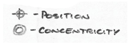
Location Tolerancing
These consist of two GT&D - Position and Concentricity. Most important when locating positions
CMM Machine
These is probe based machine that interacts with the geometry of the part making contact with the part to indicate the geometry of complex part
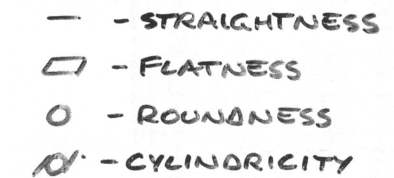
Form Tolerancing
The possible form tolerances are straightness, roundness, cylinderical & flatness.
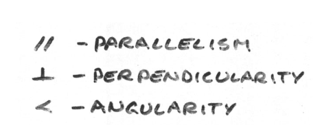
Orientation Tolerancing
Parallelism
Prependicularity
Angularity
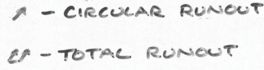
Runout Tolerancing
Tolerancing used to measure the rotational length of a part.is used
Rule #1
If a geometric sizing is the only thing present on a particular part defects are still allowed. Considered as curve, angled parts, ect.
Rule #2
For material amounts the RFS “Regardless of feature size” is the default GT unless mentioned to be MMC “Maximum material Condition” or LMC “Least material condition”
MMC
Maximum material Condition is defined as having the most material for that particular tolerancing present.
Hole - Smallest Sized Hole
Shaft - Largest Sized Shaft
*ALL THAT FIT WITHIN ITS TOLERANCING*
MMC Rules #1 and #2
#1 → This indicates that if a MMC is being using the roundness, straightness and other properties should also be included or chance of part fitting greatly reduces
#2 → Most engineers are more inclined to have MMC automatically reference on the dimensioning sheet as they feel it protects them from the possibilities of too small and not connectable parts
Surface Profile Tolerancing
Outline of the surface has a reference for how high or low that specific parts can be in elevation to one another.
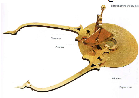
Cannon Ball Measuring Caliper
This was a caliper invented to indicate if a cannon ball was the correct size to be inserted into a cannon so that it doesn’t blow up everyone
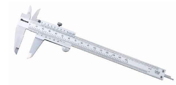
Side Calipers
Accurate to 1/1000’’ and uses the vernier scale to be more accurate. Used by closing the area you want to measure and then finding the geometry.
Micrometer
Accurate to 1/10000’’ and uses the vernier scale to be even higher in accuracy regarding these system. Used by closing the area you want to measure then finding the value it relates to.
Reading a Vernier
#1 → Start by lining up the zero value with the part
#2 → See which value on the vernier scale in perfectly in line with it’s regular rulers part and that will be the indication of the meausrement
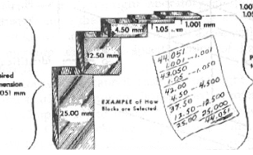
Gauge Blocks
These are block of square or rectangular shape that are used a reference height where it’s perfect to the height listed up to 1 millionth of a inch. Comes in various packages according to the number of blocks required.
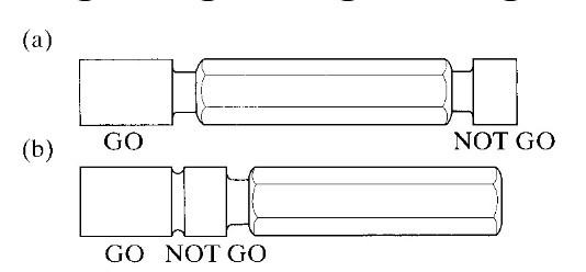
Gage Plugs
These are screw based checkers defined into two parts
Go: Smaller tolerance sizing → defined where if the screw has easy screwing without loose or challenging it is consider viable.
No Go: Larger tolerance sizing → defined where you want to ensure that diameter isn’t going to over screw itself and as a result not get stuck meaning it can only be rotated 1-1.5 times.
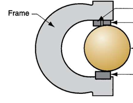
Snap Gague
These are gauge that consist of a go and no-go component, where the go it the smaller length having the part enter, and then the no go is a larger length to ensure that the part itself isn’t too small.
Dial Indicator
These are used to indicate length of a mechanic part by measuring by rotating a pin around having values of 0.001in or 0.01mm, depending on the equipment
Pneumatic Gage Principal
These work by connecting to the surface of a part, or the inside of a part, to see the flatness of it by shooting the part and tracking the amount of air released.
Electronic Amplification Gague
This is a gauge that collects the bending, compressing or stretch forces for a particular part and keeping track with electrical signal that when connecting will decode itself give readable measurements to the manufacturer.
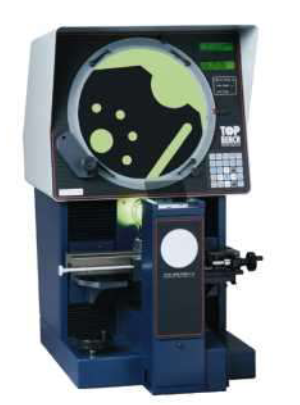
Optical Comparators
These is a super zoomed in measuring device that has two different colors for one have the material and the other about the free space and with it you can identify certain aspects such as angles and ect.
Toolmakers microscope
Includes a crosshair for measurements of very tiny parts that are very challenging to measure without tools.
Optical Flats
These are glass lens that can tell us the different surface levels for a particular material in terms of how it’s outlined.
curve → Indicates a elevation change
flat line → Indicate flat surface
bended edges → Edges worn
Surface Finish
These occur as small deactivations in production might be unavoidable.
Important surface finishes
→ Friction
→ Assembly (Glue)
→ Mechanical Properties Impacted
→ Coatings
Comparison of surfaces
There are three test that can be used to check surface finish.
Comparison with standard surface parts
Optical instruments
Stylus instruments
TIP: Fingernail see up to 0.001’’ of a material difference
Stylus Instruments
A common example is an instrument that electronically measures the difference that occurs in the heights of the material. A common example is a Talysurf
Optical Instruments
Optical Instruments uses light interference of returning beams to indicate how well aligned the surface was or if interferences would occur.
4 Elements of surface finish
Waviness - Widely space due to machinery
Lays - Created by cutter
Flaws - Cracks, holes
Roughness - Fine irregularities from the grinder or cutter
Ra vs Rz
Ra - Takes the average of the heights over the entirety of the material to compute a average result
Rz - Takes 5 different sections (Rt) and find the average of each of those parts and then gets the average of those sections
*Usually Rz is greater than Ra
What are the 3 styles of CMM
Gantry Style CMM - Provides the most accurate and stable measurements, and it is most commonly used within the industry.
Horizontal Arm CMM - These are less accurate but are smaller and place onto side areas that make it easier for acessing the purpose it provides.
Articular Arm CMM - This is the least accurate type of CMM as it is controled by the user themselves and they might not apply the necessary force of percious that the measurement needs to be as accurate as possible. controlled
CMM Touch Probe
There are 3 types of touch probes
#1 → Fixed
These are probes made of solid material that must be taken care of so that the accuracy of the measurement can be continued
#2 → Touch Triggered
These are probes that electrical components in them send signals into softwares about the specific information that they can find about the geometry of the part.
#3 → Optical
Usally a laser that measure the distances between the different surfaces but they are the least accurate probe style
Setting up a CMM machine
Calibrate the probe by taking calibration sphere measurements.
Define the parts of the datum (x,y,z axes)
Measure the part