Signal Processing (pt. 2)
 Call Kai
 Learn
Learn Practice Test
 Spaced Repetition
 Match
Match Flashcards
 Knowt Play
1/56

There's no tags or description
Looks like no tags are added yet.
Name | Mastery | Learn | Test | Matching | Spaced | Call with Kai | Chat |
|---|
No analytics yet
Send a link to your students to track their progress
57 Terms
Scan Converter
Accepts and stores echo signal information, amplitude, and location
Processes information by manipulating target information and assessing grey-scale levels
Outputs signal information in a format for video display
Analog Scan Converter (ASC)
Older technology
Associated with Cathode Ray Tube (CRT)
Images are not stable/fuzzy & needs constant readjustment
Analog Scan Converter Controls
Read Level (reject) - controls noise level & range of displayed signals
Read Zoom
Display Subdivision
Polarity Switch - inverts gray-scale patterns (black on white/white on black)
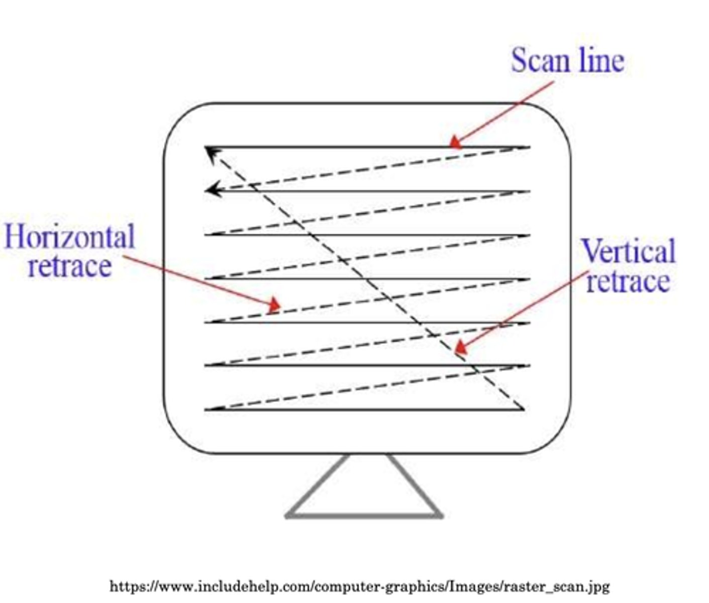
Raster
File format for storing/displaying digital images
Size is dependent on dimensions
Determines number of pixels in display
Works from top left to right, then bottom left to right
Functions of a Digital Scan Converter
Accepts analog signal - line-by-line B scan information
Converts analog signal to digital for storage
Stores digital signal
Processes information to emphasize or compress amplitude ranges
Converts digital signals to analog for output
Outputs signals in raster format for video display
Advantages of a Digital Scan Converter
Stable/uniform signal storage
Accurate & increased storage
Long life
Quick data access
Can self-check for malfunctions
Disadvantages of a Digital Scan Converter
Image artifacts
Flicker of pixels
Increased costs
Digital Scan Converter Processing Sequence
Input Signal
Analog to Digital Conversion
Pre-Processing
Signal Storage
Image Updating (related to raw data)
Post-Processing
Digital to Analog Conversion
Display
Input Signal
Analog signal leaves receiver and goes to scan converter for processing
Dynamic Range ~ 35-35 DB
Analog to Digital Conversion
Samples are taken from each pixel and that information is converted into binary numbers that represent levels of gray on the display
Digitization
Analog signals are converted into binary numbers
Sampling
Types: center, peak, average of 4+ samples of signal
Occurs every 0.1 mm along echo signal
Can increase processing time
Pre-Processing
Done before image is frozen
Assigns digitized value of each pixel to a range of values that preserves weak/low amplitude information
Compresses & emphasizes signal ranges
Determines the number of shades of gray in image
Ex. TGC, write zoom, panning
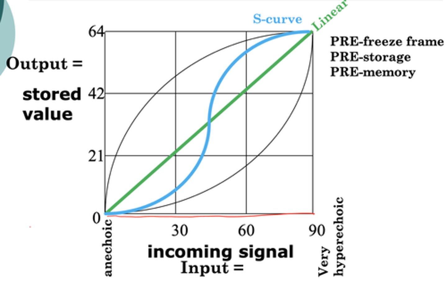
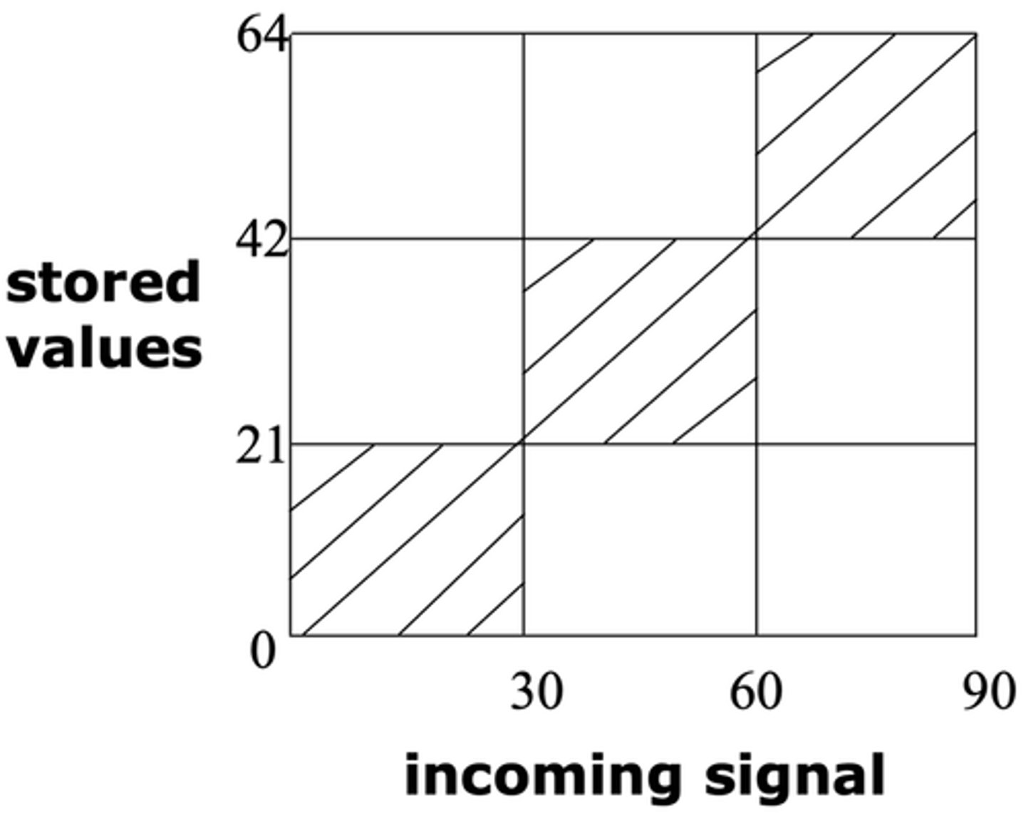
Pre-Processing Maps
X-axis = input/incoming signal
Y-axis = output/stored value
Linear Pre-Processing
Straight-line relationship
Logarithmic Compression Pre-Processing
Emphasis on low-level echoes
Fast initial increase, then a slower progression
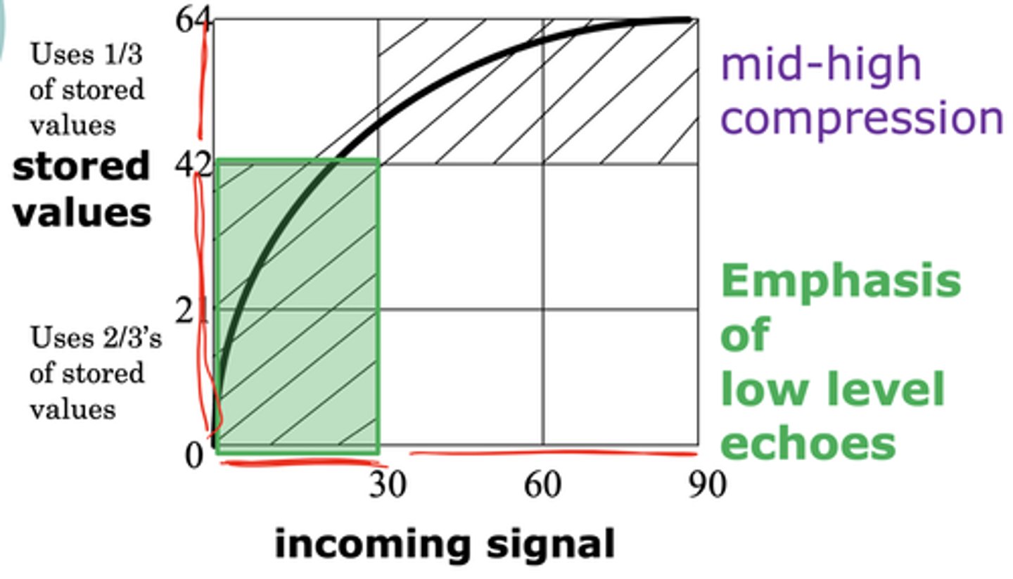
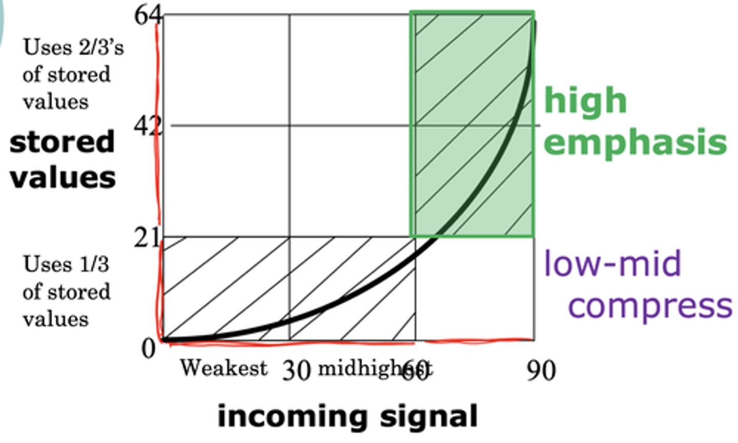
Exponential Compression Pre-Processing
Emphasis on high-level echoes
Initially increase slowly, then very quickly increase
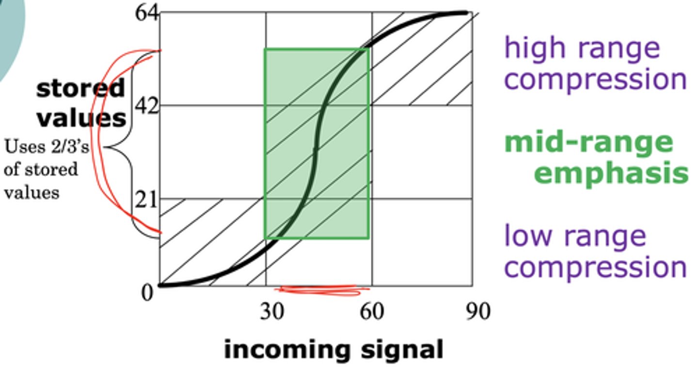
S-Curve Compression Pre-Processing
Emphasizes mid-range echoes
Signal Storage
Computer memory stored in binary format
Multi-level checkerboard -> more layers = more shades of grey
Permits:
Freeze frame & cine-loop
Frame Insertion - updating/averaging frames
Interlacing - prevents flicker
Converting to Binary Code
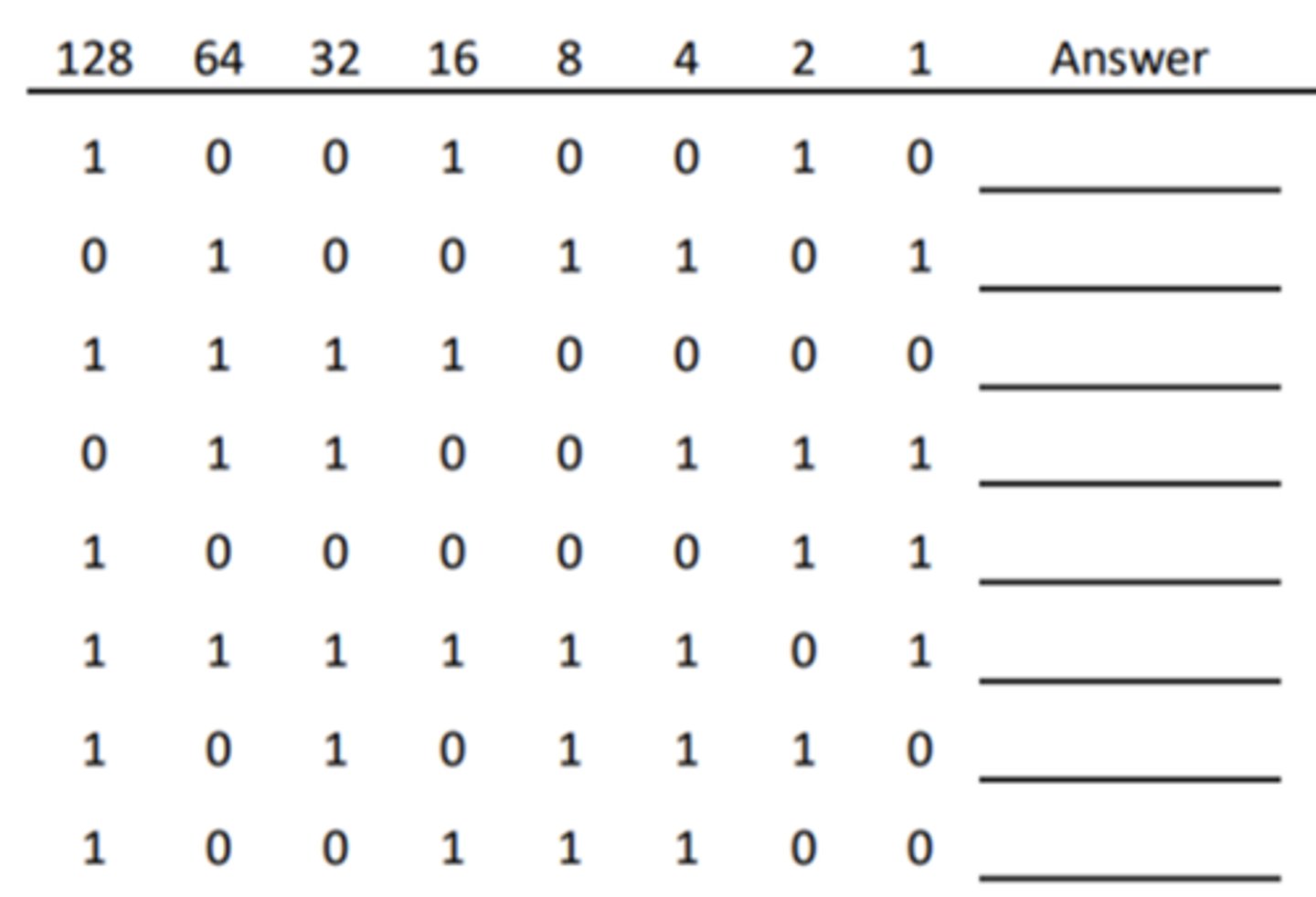
Bit
1 or 0
Building blocks of words in binary code
How to calculate total number of bits for storage
Dimensions of a board x number of boards
Usually between 1-3 million
Word
Combination of bits
Treated as single entity
Corresponds to a location in space
Number of bits dictate the number of different configurations/values it can represent
Byte
8 bits
Total number indicates total number of characteristics that the storage device can hold
Address
Location of checkerboard
Guides system to know where each signal should be placed on the display
Pixel
Location on display monitor
Size has inverse relationship with size of matrix board
Contributes to spatial resolution of monitor
Larger number = smaller size = better image resolution
Formula for Pixel Size
Image depth ÷ one depth dimension of matrix
Changing the spatial resolution on the ultrasound display does not change the axial/lateral resolution of the scan line or sound beam
Image Updating
Uses algorithms to determine if new information needs to be displayed or if the information can remain the same
Last Value Algorithm
Total replacement of old signals with new ones
Compound/Integration/Fraction Algorithm
Old signal value is compared to the new one
If old is > new = no change
If old is < new = percent (or total) of new value is added
Interpolation
Averages signals to fill-in missing pixel information
Post-Processing
Occurs after image is frozen
Does not change stored values
Determines gray scale values on displayed image
Signals are read from the raster and stored in the register
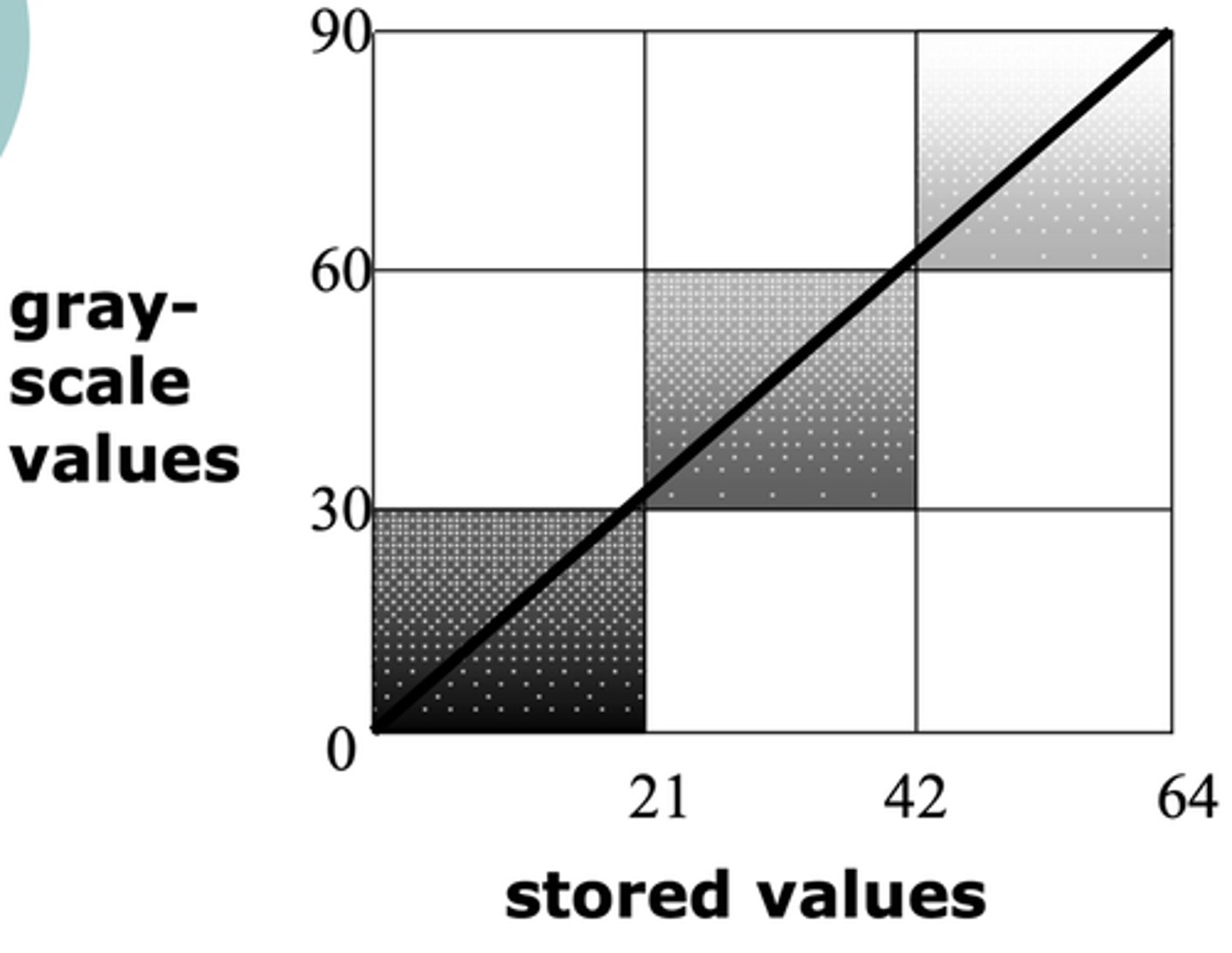
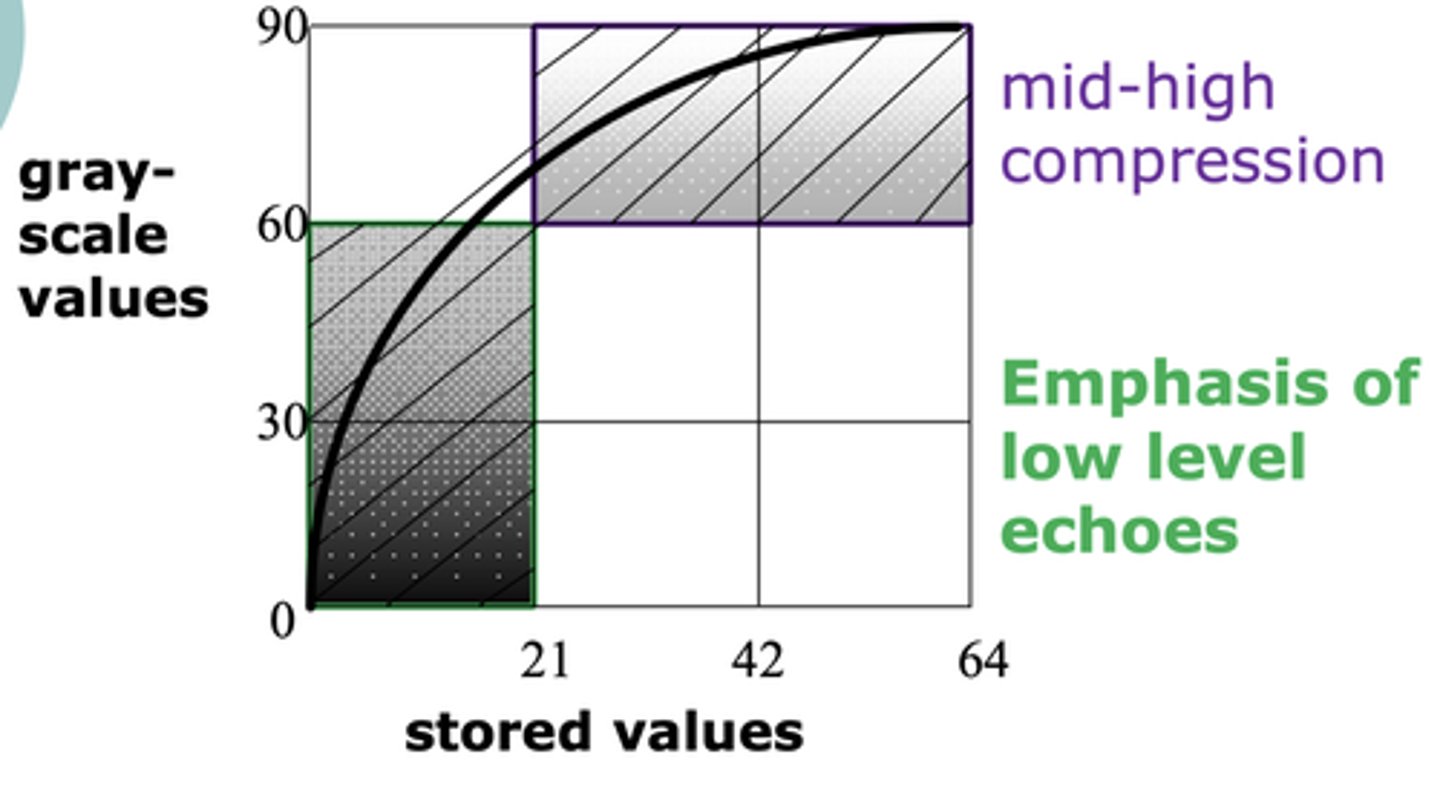
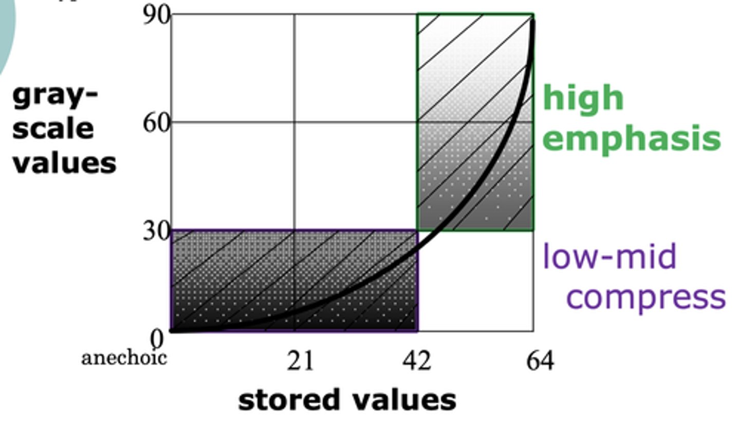
Post-Processing Maps
X-axis = input/stored value
Y-axis = Output/displayed gray scale values
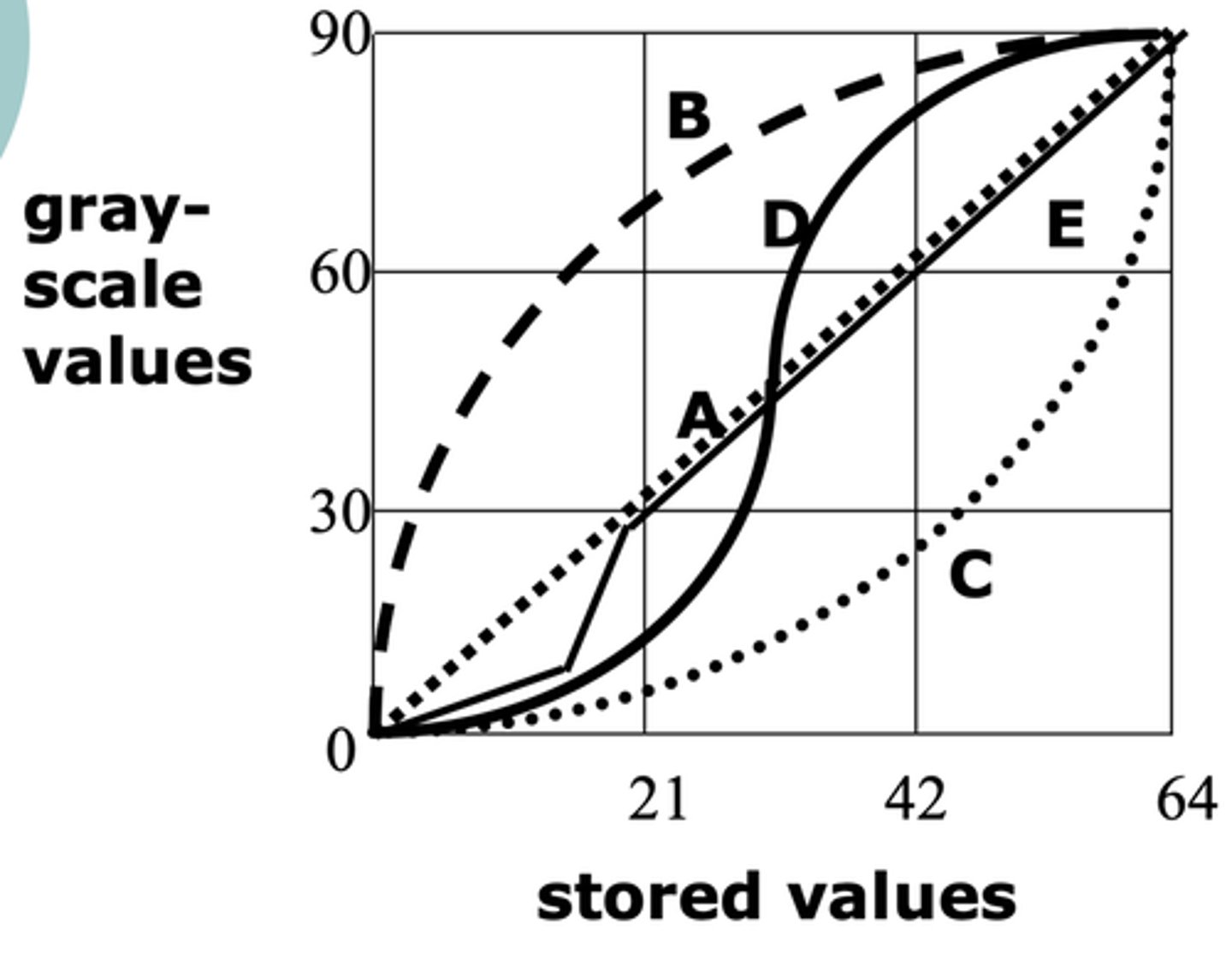
Linear Post-Processing
Uniform distribution
No specific range emphasized
Logarithmic Post-Processing
Emphasis on low-level echoes
Exponential Post-Processing
Emphasis on high-level echoes
S-Curve Post-Processing
Emphasis on mid-range echoes
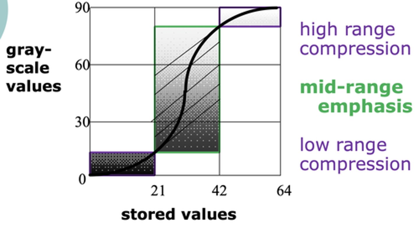
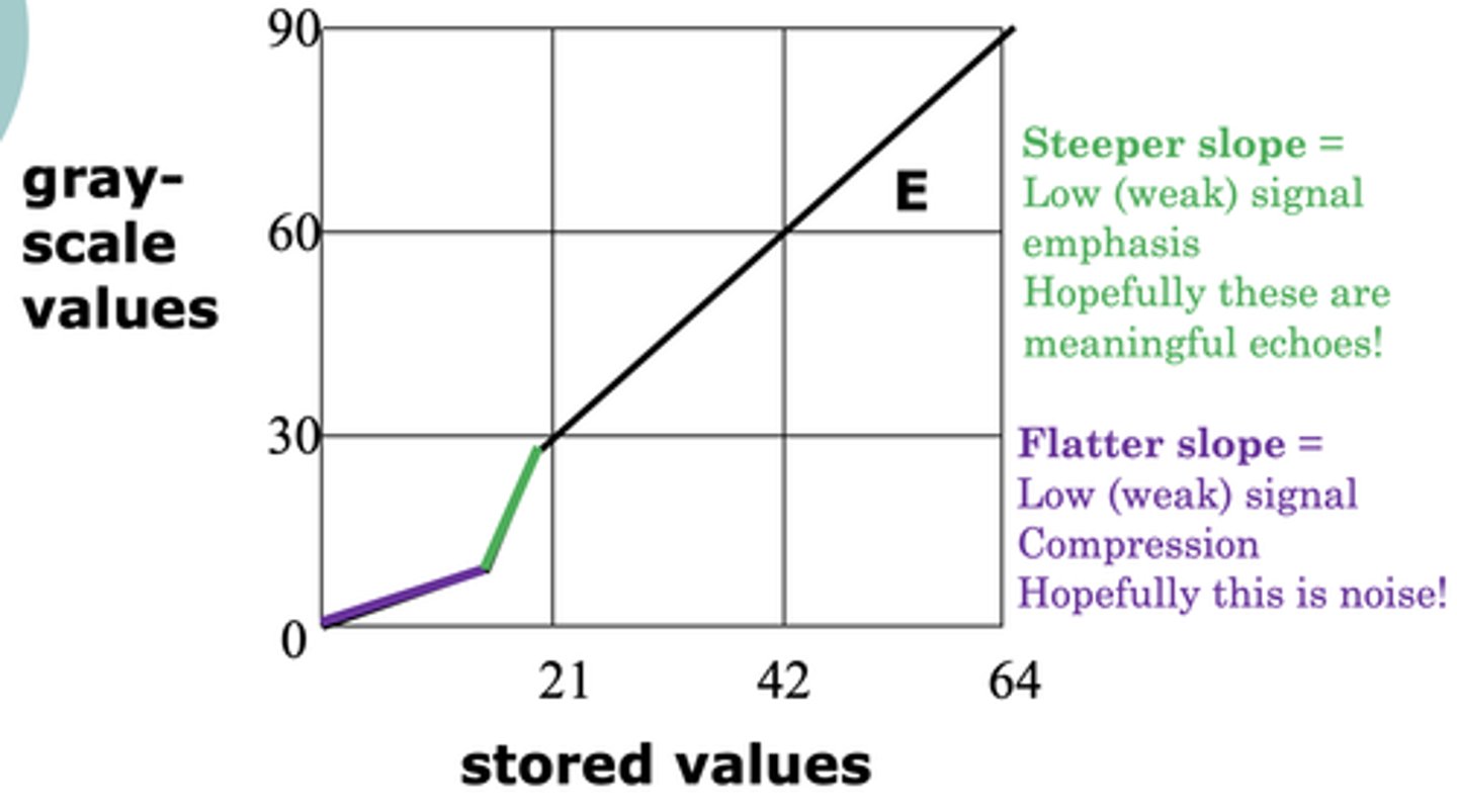
E-Curve Post-Processing
Steeper slope emphasize low-level echoes
Flatter slope compresses low-level echoes
Digital to Analog Conversion
Digital signal leaves register and is converted back into an analog signal for video display
Functions of Displays
Converts electrical energy to light
Signal storage & display
Types of Displays
Light Emitting Diode (LED)
Liquid Crystal Display (LCD)
Cathode Ray Tube (CRT) -> Oscilloscope & TV monitor
Minimum frames/second on a TV monitor
30
Minimum images/second on a TV monitor
16
For continuous, uninterrupted motion
Components of a CRT
Cathode (electron gun)
Control Grid
Focusing anode, grid, cup, coil or collimator
Accelerating anode or coil
Deflecting plates, coil or yoke
Anode (Phosphor screen)
CRT Image Creation
Electrons are released from cathode
Negative electrons move towards positive anode
Electrons pass through control grid
Internal focusing anode, grid, or cup determine beam diameter
Electrons accelerate by anode (internal electrical) or coil (external magnetic)
Internal deflection plates or external magnetic deflection yokes determine beam position
Electrons strike anode/phosphor screen and emit light
Light color is determined by phosphor material
Amount of light is determine by how many electrons strike anode
Film
Light strikes solver bromide crystals and forms image
Developed in darkroom
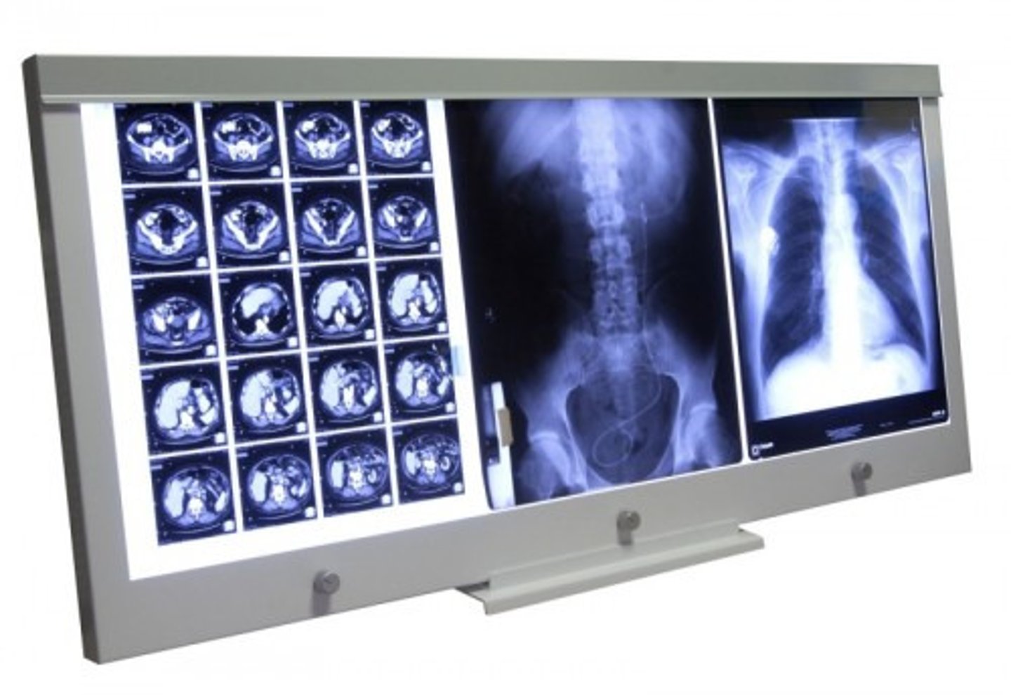
Laser Printer
Automated film handling & developing
Good gray scale
No image distortion
Expensive
Thermal Printer
Heat sensitive paper
Does not age well
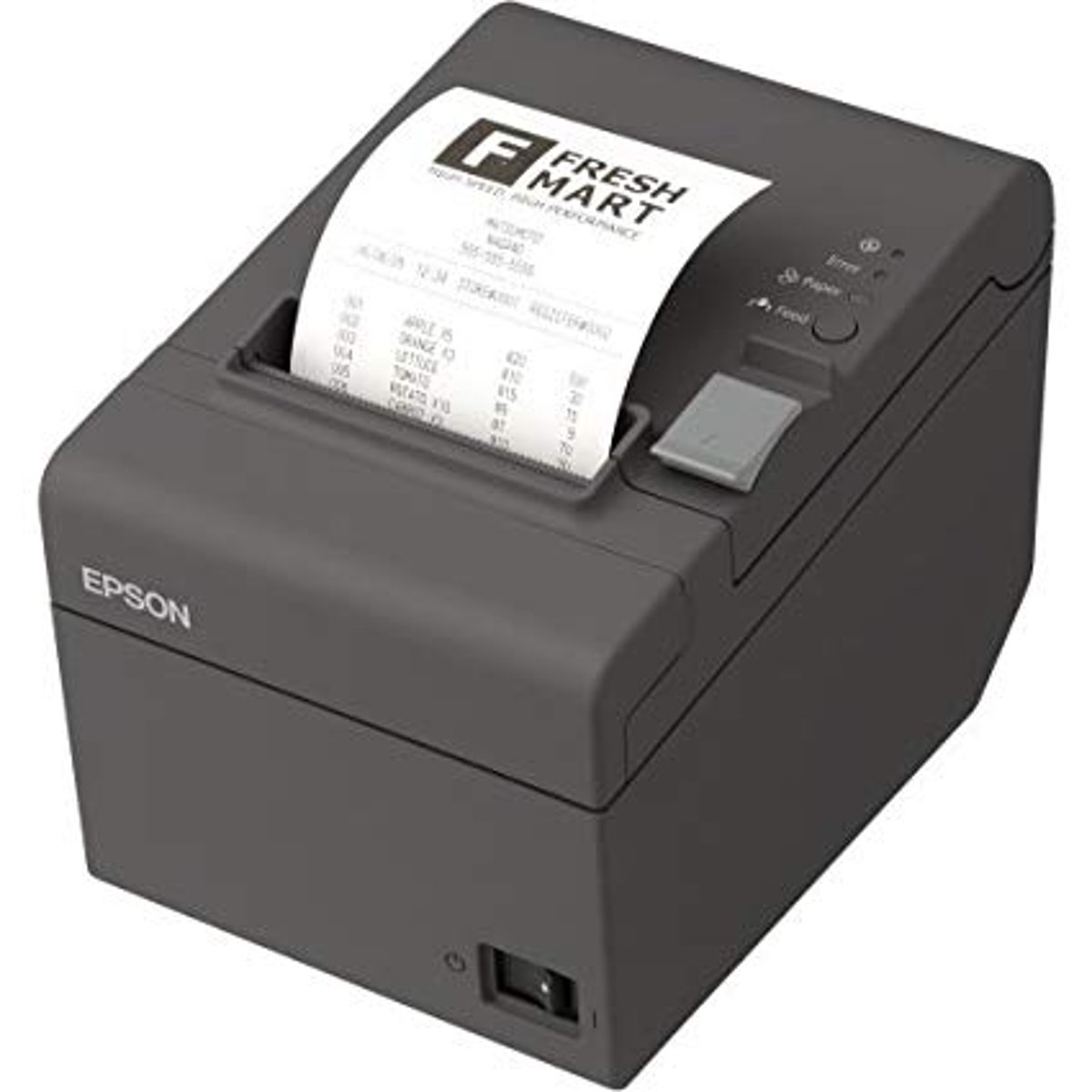
Color Thermal Printer
Color is pressed on thermal paper and heated so that it bleeds/melts onto the paper

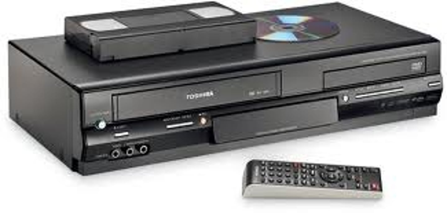
Video Tape Recorders (VTR, VCR)
Contain magnetic oxide particles
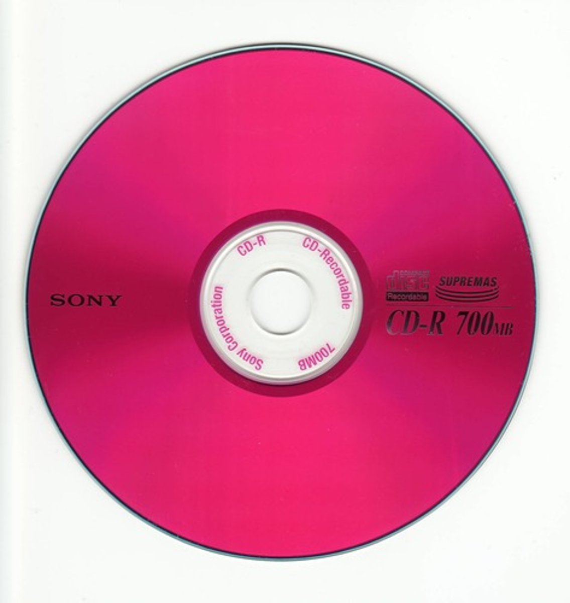
Optical Discs
Use laser to write information
Magneto-Optical Discs
Use laser to write information
Can be erased and rewritten magnetically
CD-R & DVD
Types of optical discs
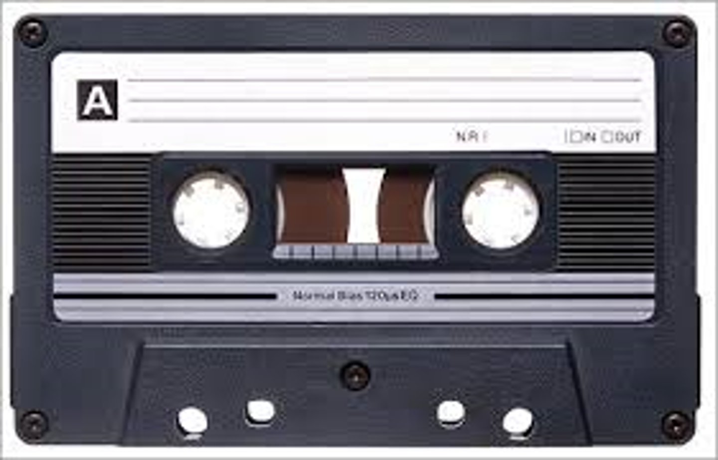
Digital Archive Tape (DAT)
Digital Video Recorder (DVR)
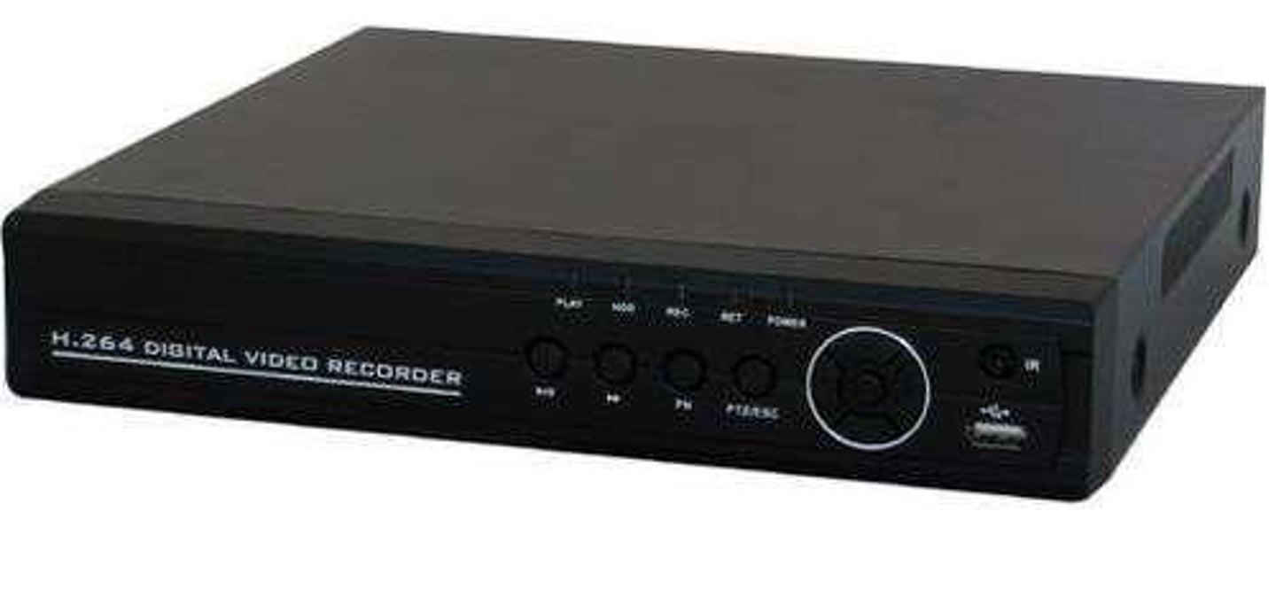
Solid State Hard Drive
No moving parts - helps with failure rates