Naval Weapons Exam 2
 Call Kai
 Learn
Learn Practice Test
 Spaced Repetition
 Match
Match Flashcards
 Knowt Play
1/112

There's no tags or description
Looks like no tags are added yet.
Name | Mastery | Learn | Test | Matching | Spaced | Call with Kai | Chat |
|---|
No analytics yet
Send a link to your students to track their progress
113 Terms
electronic combat (EC)
military action involving use of electromagnetic energy to determine, exploit, reduce (or prevent) an enemy’s use of EM spectrum, and actions which retain friendly use of EM spectrum
commonly referred to as electornic warfare (EW)
EC and EW are interchangeable
three components of EW
electronic support (SW)
electronic attack (EA)
electronic protection (EP)
electronic support (ES)
passive surveillance of EM spectrum
surveillance of enemy
strength
intention
warning of target/homing
Signal Intelligence (SIGINT) (ES)
electronic intelligence (ELINT)
info derived from emissions other than comms (emphasis on radar)
communications intelligence (COMINT)
info derived from communications
bandwidth
range of frequencies detectable by a receiver
receiver sensitivity
minimum power signal needs to be detected
bandpass filted
passes only certain range of frequences through
probability of intercept
probability signal will be detected
signal analysis
manually or electronically examining a received signal to categorize it
parametric data
characteristics of received signal (RF, PRF, PW, scan rate/type, etc.)
ES receiver design requirements
wide spectrum surveillance- frequency spectrum being searched must be large
wide dynamic range - receiver must be able to receive and process very weak and very strong signals
unwanted signal rejection: discriminate against other signals that are similar in frequency to signal of interest
angle of arrival measurement capability: locate transmitter by triangulation
signal analysis capaility: identify signal based on its parameters and associate it with specific threat
display: type of display dictated by way receiver is used (audio, warning lights, alphanumeric, etc.)
direct detect receiver
designed to indicate (via alarm) presence of a signal within its sensitivity and bandpass
reliable, small in size, lightweight, cheap
radar warning receiver (RWR) in aircraft indicates presence of and bearing to a contact that has been predetermined hostile based on parametric data
limitation of these systems: they typically incorporate a wide bandpass. why is that a problem?
excess noise, especially in dense EM environments
high false-alarm rates
electronic attack (EA)
prevent or reduce enemy use of EM spectrum
can be employed against enemy sensors and communication systems
interferes with operation of air and surface defense system sensors to reduce info content and induce errors
4 major classes of EA
jamming
denial (noise)
deception (range, angular, velocity)
medium modifiers
change electrical properties of medium between sensor and target
improving own-platform stealth
apply radar-absorbing material
use decoys
destruction of enemy sensor systems
physical destruction via blast or fragmentation warheads
denial jamming tactics
stand-off jamming
self/escort jamming
deception jamming tactics
angular deception
range deception
denial jamming
designed to overload opposition’s receiver so that its use is denied to enemy
creates noise signal powerful enough to mask signal receiver is trying to detect
advantages
simple to implement
disadvantages
effectiveness is limited by max radiated power
countermeasures are simple and widely employed
vulnerable to home-on jam-type missile systems
jamming tactics - stand-off jamming
jamming platform stays outside lethal range of enemy weapons, but doesn’t escort other units
safer for jammer (GOOD)
lower jamming power on target (BAD)
jamming power may go off-target (BAD)
jamming tactics - self/escort jamming
jamming aircraft escorts strikers in, or the strike aircraft provide their own jamming
easier to ensure jamming energy paints target site (GOOD)
higher jamming power on target (GOOD)
susceptible to energy home-on-jam (HOJ) missiles (BAD)
deception jamming
instead of trying to “mask” targets, the jamming creates synthesized (fake) targets to overwhelm tracking logic and/or confuse system
angular deception jamming
radar antennas are not “perfect” and do not reflect only a single beam
this results in prevalence of “sidelobes” about main beam
transmit upon radar sidelobe detection
any energy received by radar system is “assumed” to have originated in main lobe
if jamming platform’s transponder can “sense” presence of a sidelobe, it can transmit strong pulse toward radar and “spoof” radar into thinking target is present in main lobe
other angular deception methods
“cross eye”
very effective against active monopulse missile radar
missile using active radar for guidance finds its target by aligning itself perpendicularly to wavefront of receive echo
cross eye jamming changes orientation of echo wavefront
wingtip transponders receive radar energy, one immediately retransmits, other waits to be “interrogated” by immediate transponder before it responds
transponders are essentially transmitting out of phase with one another
result is reflected waveform is “distorted” and missile will attempt to align itself with distorted wave, missing target
range deception jamming
principle victims are fire control radars
spoils fire-control solution by giving multiple targets at different ranges
jammer sends multiple copies of return echo with time delays to confuse range calculation (makes it appear further away)
expendable decoys
decoys are thruway devices designed to imitate a real target
chaff - radar countermeasure
aluminum-coated fiberglass filaments released into atmosphere to produce larger radar cross section than the target
flare - infrared countermeasure
chemical infrared source that mimics target signature at a higher power
reflector - radar reflector
and mobile or static off-board active transmitters
target masking and modification
“you can’t hit what you can’t see” - an undetected target has highest probability of survival
after platform shape
use angles that reflect in directions that are not towards radar
avoid flat, cylindrical, parabolic, or conical surfaces perpendicular to transmission
destructive interference to reflect only part of incident radiation
coat surface with a radar absorbing material
stealth: radar absorbent material
surface absorbs energy (heats up)
stealth: destructive interference
reflected waves (destructive interference) off semi-transparent coating
electronic protection (EP)
protect friendly combat capabilities against undesirable effects of enemy electronic attack
most understand various forms of EA that radar is likely to encounter to protect against them
must train operator to recognize various countermeasures used and to select appropriate combination of options to counter each
radar design for EP has 3 areas:
radar parameter management
signal-processing techniques
radar design philosophy
radar parameter management
power
EA is power battle- whoever is stronger and more powerful will win
frequency
some radars are designed to change frequency, making deception and jamming difficult
pulse repetition frequency (PRF)
changing PRF in a random fashion is effective because EA depends on constants
antenna design
can prevent jammer or deceiver from affecting radar at many bearings (i.e. low sidelobe levels)
scan pattern
influences amount of energy directed toward radar target (random fashion instead of circular), making it difficult to predict
electronic protection table

electro-optic spectrum
electro-optic systems operate in the optical region of the E-M spectrum, between x-rays and microwaves, and includes ultraviolet, visible, and infrared regions
E-O in millions of MHz, in wavelength in μm
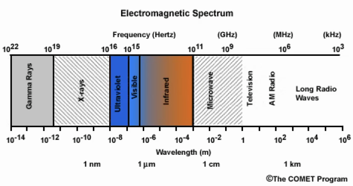
EO system units
by convention use wavelength rather than frequency
standard unit of measurement for EO spectrum wavelength is micron
micron is 10-6 m (μm or μ or microns)
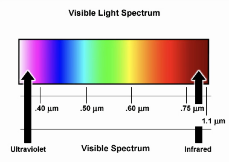
IR portion of Em spectrum
6 “bands” of the EO spectrum
UV (0-0.4 micrometers)
visible (0.4-0.7 micrometers)
near IR (0.7-3)
mid IR (3-6)
far IR (6-15)
extreme IR (15-20)
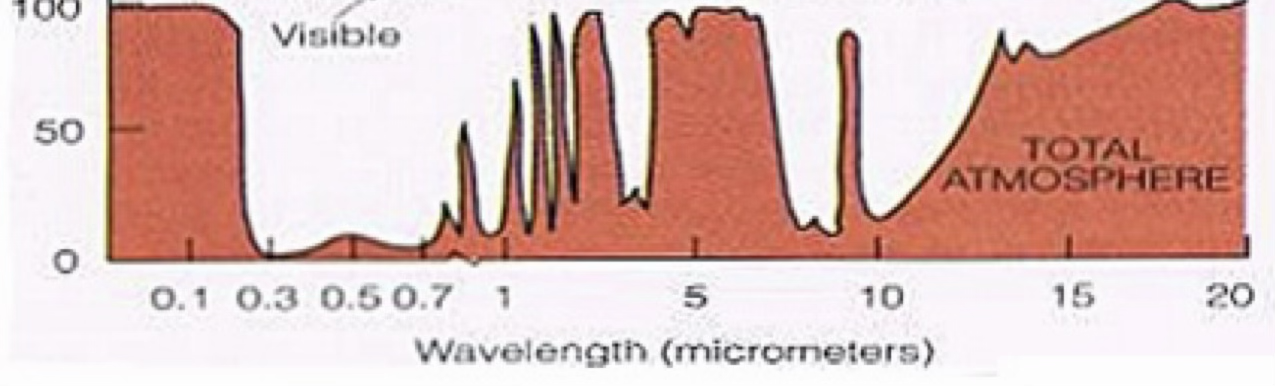
EO system types
visible imaging systems
0.4-2.0µm
detects/amplifies visible energy
example: night vision goggles
infrared imaging systems
3-14µm
detect radiated or reflected IR
example: thermal imagers
EO system: visual imaging systems
amplify very low levels of ambient light

EO system: IR systems
detect heat from a target

EO system vs. RADAR
ADV
passive (covert)
precision imaging/tracking
VID possible - FLIR/NVG
DISADV
susceptible to atmospheric conditions (smoke, fog, rain)
shorter max range
range harder to determine
radiometric quantities - radiant energy
Q
total energy transported in form of EM waves from a source
entire amount of energy radiated from a source during a given time interval
unit: Joules (J)
joule = watt * second

radiometric quantities - radiant flux (power)
Φ (“phi”)
rate of flow of radiant EM source
energy per time radiated from a source
equation
Φ = dQe / dt
unit: J/s = Watts (W)
radiometric quantities- radiant exitance
M
power put per unit area leaving a surface and radiated into space
exitance characterizes a self-emitting source that is producing energy
equation:
M = dΦ / dA (surface area)
if power is uniform across surface, M = Φ / A
units : watts/area = W/m²
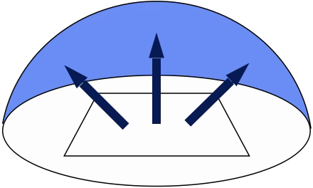
radiometric quantities- irradiance
E
radiant power per unit area incident upon a surface
irradiance characterizes a passive receiving surface
equation
E = Φ / A
unit: W/m²

radiometric quantities - radiant intensity
I
brilliance of a source of EM energy over entire eletromagnetic spectrum
flux emitted per solid angle from an isotropic emitter (point source)
think power density measured from a point source
equation
I = dΦ / dΩ
Ω = solid angle = 4π sr
unit: W/sr
sr = steradian

radiometric quantities - radiance
L
power radiated per source area per solid angle
think power density across an extended source
equation:
L = Φ / AΩ
L = d²Φ / dA * cosθ * dΩ
unit: W / (sr * m²)

sources of EO energy
EVERYTHING IS AN EO SOURCE
conservation of energy
when EO energy hits an object it either
absorbs - absorptivity (α)
reflects - reflectivity (ρ)
passes through - transmissivity (T)

blackbodies vs. greybodies
blackbody
an ideal (theoretical) substance that absorbs ALL incident energy and then reradiates that absorbed energy with complete efficiency
perfect absorber, perfect radiator/emitter
stars are approximated as blackbodies
greybody
all other real objects
EO energy may either absorb, reflect, or pass through
blackbody
absorptivity = reflectivity = transmissivity = EO energy
all incident energy absorbed
greybody
most objects absorb some fraction of energy and reflect the rest
no energy transmit through
reflected radiation
reflect EO radiation is important for military operations
allows eyes to detect and differentiate between objects during the day
at night, however, ambient EO radiation goes down, making it difficult for humans to see without an aid (such as NVGs)
types of illumination
natural illumination
solar illumination - the sun, our best illuminator, but is not available at night
lunar illumination - the moon, primary illuminator at night; reflects about 7% of sunlight
night sky illumination - at night, sky gives off near-IR energy (“air glow”) that can be useful for NVGs to intensify; starlight; auroras
artificial illumination
lights from cities, vehicles, weapons, flares, etc.
two types of radiators
selective radiators
emit energy as discrete wavelengths
ex: exhaust gasses, laser energy
thermal radiators
emit energy over a span of wavelengths
ex: hot metal, terrain, people
light amplification (low-level-light (LLL) systems)
enhances existing light
require some background illumination
do not work in total darkness
saturate if too much light is present
resolution dictated by # / size of elements
amplifies visible and near-IR light

NVDs in combat
huge tactical advantage against combatants without the technology
can communicate visual signals to friendlies covertly - IR signals, lasers
lasers
is light, a form of EM radiation
like radars, lasers can operate in pulsed or continuous wave modes (blinking vs. solid)
laser will have nearly-constant wavelength over its entire life
reflected laser energy can be used for targeting purposes
can be used for ranging (from operator)
infrared systems
targeting / ranging lasers
thermal imagers
IR seekers
thermal imagers
see both emitted radiation and reflected radiation
rely on Mcontrast to discern objects

infrared sensor basics
require no visible light
detect IR energy emitted from targets
passive (target is source)
no direct ranging capability
covert
limitations
background limited - predominant source of noise is the environment
noise limited - predominant source of source is the detector itself masking the target signal
passive IR detectors: exitance contrast
ability to discern target is based on DIFFERENCE in energy detected from target vs. background
IR imager performance
spatial resolution
imaging system’s ability to distinguish separate objects
thermal resolution
ability to detect small variations in temperature differences
changes too small to be distinguished from background noise will not be detected
background limited
lack of contrast between target and background
noise limited
sensor’s internal heat masks signature of target
EO countermeasures
laser dazzlers (visual defense system)
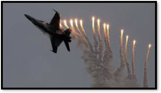
IR flares
IR staring sensors
requires many detecting elements and produces output in parallel (sends entire image from each detector element simultaneously)
fast but expensive
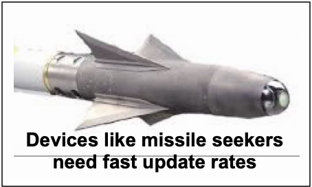
IR scanning sensors
serial scan
rotating mirror scans sequentially
one piece of the picture at a time
less expensive than staring sensors
prone to mechanical failure
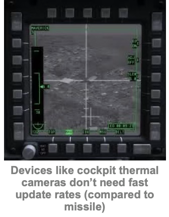
good when fast update rate not needed
thermal signatures: aircraft
nose cone
leading edges of wings
engine inlets and nozzles
exhaust plume
thermal signatures: armored vehicles
engine and exhaust
mechanical tracks from friction
metal body if in sun

thermal signatures: ships
engine exhaust
masts when used
metal body in sun

SONAR
sound navigation and ranging
SONAR - why?
options for finding things underwater
RADAR
radio frequencies don’t propagate well in water
limited range and resolution
Light (EO)
very limited range (10s of meters)
may be useful at shallow depths)
Magnetic Signatures
limited range (100s of meters)
Sound
speed of propagation is fast enough
tactically significant ranges are possible
while lower resolution than light, resolution is good enough for our applications
SONAR vs. RADAR 3 main similarities
just as with RADAR (Smin), there is a min threshold that defines when SONAR contact is possible (detection threshold, DT)
same signal losses as RADAR when SONAR energy propagates: spreading, absorption, scattering
like RADAR, there is a set range beyond which your system (and/or operator) doesn’t register a contact because the incoming energy is less than Smin or DT
SONAR is a new sensor, but one that acts a lot like what we’ve seen already
SONAR vs. RADAR 2 major differences
where RADAR systems use EM energy, SONAR systems use sound energy
where RADAR systems operate in air, SONAR is used in water
two ways to exploit sound first one
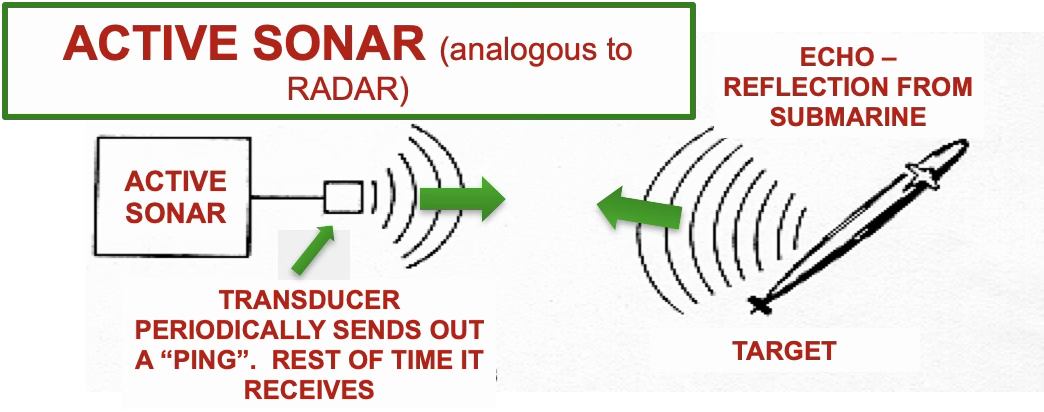
active SONAR (analogous to RADAR)
two ways to exploit sound second one
passive SONAR (analogous to EO sensors)

wave propagation
sound originates as wave motion from a vibrating source and requires a medium (air or water) to move through
two forms of wave propagation:
transverse - disturbance perpendicular to direction of propagation
E-M waves (previously discussed in RADAR)
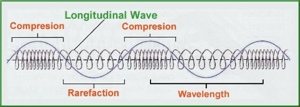
longitudinal - disturbance in same direction as propagation
vibrations - causes series of compressions and rarefactions
amplitude measured at a single point will look like a sine wave
wave represents pressure differences around a static level
sonic concepts, 3 elements required to tactically exploit sound energy:
source - any
medium - an elastic medium (air or water)
detector/receiver
λ = v / f
speed of sound in water
v = f λ
v / c = ~1500m/s (v is speed of sound in water)
speed of sound in water varies from point to point in ocean
speed of propagation, frequency and wavelength depend upon 3 factors
temperature
pressure
salinity
temperature is single most influential factor in affecting speed of sound in water
as temperature increases,
speed increases
predominant factor affecting speed
Δ 1°C = Δ 3 m/s v
as pressure increases,
speed increases
predominant factor at very large depths
Δ 3 ft depth = Δ .017 m/s v
as salinity increases,
speed increases
Δ 1ppt of salt = Δ 1.3 m/s v
sound speed =
pressure, salinity, temperature
typical deep ocean sound velocity profile (SVP)
surface layer (shallow - changes daily)
seasonal thermocline (temp and v change with seasons)
main thermocline
temperature decreases w/ depth, causing decrease in v
independent of surface layer temp changes
deep isothermal layer
temperature is constant
pressure has most significant effect on v
sonic layer depth (SLD) → deep sound channel (DSC) (sound will get trapped in region) → critical depth → depth excess

ray propagation theory
sound speed gradient with respect to horizontal changes of location can be assumed to be zero
major gradient of interest therefor is vertical (depth) gradient
if ship at surface of ocean makes a sound, it radiates in all directions, transferring its energy from particle to particle, forming a propagating wave
ray is created when you draw a line from source in direction of energy propagation
when ray enters a part of water that has different characteristics, it chantes direction and speed (bends)
Snell’s law
rays will bend when passing between 2 different mediums (refraction)
sound will always bend toward region of slower speed (sound is lazy)
tactical significance of snell’s law
why do we care how sound bends?
we use sound to detect, localize, classify, track our TOIs, so we need to know where sound will go so we can exploit it
sound will bend toward where it can go slowest
how do we know what sound velocity profile looks like?
historic data updated with real time readings
why do we care?
this info will inform our tactical game plan
how do we measure speed of sound in real time?
expendable bathythermograph (XBT)
sound propagation in isovelocity gradient
occurs in isothermal (constant temp) - constant SVP
long ranges, straight line rays with little to no angle change
sound propagation in negative gradient
temperature decreases w/ depth, causing sound speed to decrease w/ depth
sound bends down
shadow zones formed - region where sound intensity is 0 (common near sea surface)
sounds propagation in positive gradient
temperature increases w/ depth, causing sound speed to increase w/ depth
sound bends up, then reflect off sea surface, causing continued “bouncing” - causes sound to travel farther
possible shadow zones
layer depth phenomenon (positive over negative)
layer of warm isothermal water over water with a negative gradient
critical ray defines sonic layer boundary - this is where sound speed is highest (sonic layer depth)
rays split at sonic layer - one half bends up, other half bends down, forming SZ
subs use SZ to escape detection
SZ = shadow zone
sound propagation paths
direct path
surface duct
half channel
sound channel
convergence zone (CZ)
bottom bounce (BB)
direct path
simplest propagation path
straight line path btwn source and receiver with no reflections
only seen at close ranges

surface duct
positive velocity gradient - refracts sound back towards surface, where it is repeatedly reflected at surface
surface duct can produce long ranges
both source and receiver must be in sonic layer
only ray paths trapped are considered surface duct

half-channel
cold isothermal water causes positive velocity gradient from surface to bottom
essentially surface duct that exists all the way down to the bottom
produces very long ranges
no shadow zones

sound channel
in deep ocean, negative speed gradient overlays a positive speed gradient, forming sound channel
sound rays are refracted back and forth in a horizontal channel
longest range transmission path available
only loss is absorption

convergence zone
negative gradient over positive gradient in extremely deep water
need >200m depth excess
sound bends intially towards greater depths due to decreasing temp, until it goes so deep that it bends upward back to surface
a CZ is typically about 50km from source
beyond CZ is a zone of silence as all rays diffract downward, followed by another CZ about 50kms later
amount of depth excess determines zone width

bottom bounce
ray penetrates down to ocean bottom, hits, and reflects back towards surface
ray continues to bounce between surface and bottom until it dissipates
needs relatively flat, smooth, hard bottom
detection threshold (DT)
minimum received signal strength above the noise floor required for a (human) operator, using installed equipment, to detect a target 50% of the time
smaller DT = better detection ability
S - N >(or equal to) DT
passive sonar equation
S - N = DT (Source - noise = detection threshold)
S = SL - TL (source level - transmission loss)
N = NL - DI (noise level - directivity index)
Signal (SL - TL)
source level (SL)
for PASSIVE sonar operations
noise generated by target (self-noise)
could be operating machinery, propeller noise, hull flow noise, etc.
transmission loss (TL)
passive SONAR (like EO):
target puts out specific amount of sound. as it travels through the water, it is delayed, distorted, and weakened, resulting in transmission loss
three categories of loss: spreading, scattering, absorption
noise level (NL)
other sources of sound make it more difficult to hear targets of interest “noise” can come from 2 sources:
your ship → self noise, NLs (dB)
other “stuff” → ambient noise, NLa (dB)
NL = NLs + NLa (power sum)
kinds of noise - broadband vs. narrowband
broadband signal - gives off wide range of frequencies (think white light)
narrowband signal - gives off specific frequency/frequency ranges (think laser)
in general, you are listening for man-made (narrowband) sources; competing noise may or may not obscure your target based on the frequency/frequencies at which they broadcast
self noise, NLs
machinery noise
originates from propulsion plan (pumps, reduction gears, generators, etc.)
narrowband (specific frequency)
flow noise
caused by relative motion between an object (hull) and water around it
broadband (wide range of frequencies)
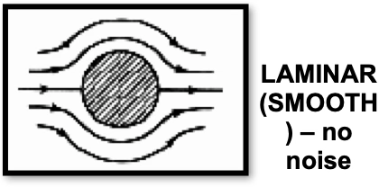
high speed or hull fouling (animal life on hull) causes turbulent flow which causes increased flow noise
cavitation
caused by ships propeller generating local pressure drops where steam bubbles form and subsequently collapse causing sharp hissing noise
broadband
ambient noise, NLa (bosh)
biological ‘
produced by marine life
might be narrowband (depends on frequency emitted)
ocean traffic
at close ranges, noise is over a wide spectrum of frequencies
at long ranges, only low frequencies are present
seismic
movement of earth (earthquakes)
hydrodynamic
caused by movement of water
includes tides, current, storms, wind, rain, etc.
NLa = B + O + S + H