Lossless Transmission Lines (Part-V)
 Call Kai
 Learn
Learn Practice Test
 Spaced Repetition
 Match
Match Flashcards
 Knowt Play
1/26

There's no tags or description
Looks like no tags are added yet.
Name | Mastery | Learn | Test | Matching | Spaced | Call with Kai | Chat |
|---|
No analytics yet
Send a link to your students to track their progress
27 Terms
Ṽ_g
(i)

Z_g
(ii)

Ĩ_i
(iii)

A’
(iv)

A
(v)

Ṽ_i
(vi)

Z_in
(vii)
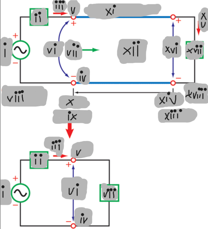
Generator
(viii)

d = l
(ix)

z = -l
(x)

Transmission Line
(xi)

Z0
(xii)

d = 0
(xiii)
z = 0
(xiv)

Ĩ_L
(xv)

Ṽ_L
(xvi)

Z_L
(xvii)

z = 0
(xviii)

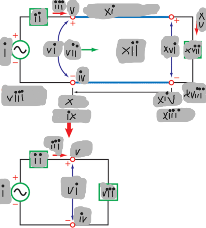
Generator-End Equivalent Circuit
From the generator’s viewpoint, the transmission line can be replaced by its input impedance Z_in
Ṽ_i = ((Ĩ_i)(Z_in))
Input Voltage Ṽ_i: Voltage at the generator end of the line
Ṽ_i = ((Ṽ_g)(Z_in))/(Z_g + Z_in)
Voltage Divider Relation for Input Voltage: Generator-end voltage expressed using source and input impedances
Ṽ_i = (V0^+)e^(jβl) + Γe^(-jβl)
Input Voltage from Traveling-Wave Expression: Voltage at the line input using incident and reflected waves
V0^+ = (((Ṽ_g)(Z_in))/(Z_g + Z_in))(1/(e^(jβl) + Γe^(-jβl)))
Incident-Wave Amplitude (V0^+): Forward traveling-wave amplitude expressed in terms of source quantities
Incident Wave
Wave traveling from the generator toward the load
Reflected Wave
Wave traveling from the load back toward the generator.
Transmission-Line Boundary Condition at the Load
Condition relating incident and reflected waves through the load impedance
Transmission-Line Boundary Condition at the Source
Condition relating line voltage/current to the generator source and source impedance.