Equip Oper/Main Test 2: Prime Factors Rad Technique
 Call Kai
 Learn
Learn Practice Test
 Spaced Repetition
 Match
Match Flashcards
 Knowt Play
1/51

There's no tags or description
Looks like no tags are added yet.
Name | Mastery | Learn | Test | Matching | Spaced | Call with Kai | Chat |
|---|
No analytics yet
Send a link to your students to track their progress
52 Terms
Four prime exposure factors
Voltage = kVp
Current = mA
Exposure time = secs or fraction of secs
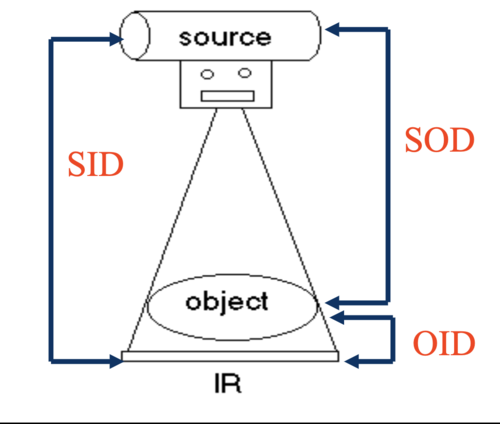
Distance = SID, OID, SOD
Kilovoltage peak (kVp)
controls how fast electrons are send across the tube aka tube potential; increasing kVp increases scattered photons reducing image quality; most kVp settings are set per thickness of bone on technique charts; controls details such as
Beam quality
Beam energy: direct relationship so increase in kVp = increase in energy
Beam penetrability: direct relationship so increase in kVp = increase in penetrability
Subject contrast (not digital image contrast)
Contrast - Image vs. Subject
Subject contrast = is the degree of density difference between 2 areas on a radiograph which makes it easier to distinguish areas; ex/ liver vs. lung; described as Gray Scales:
Short scale of contrast = high contrast (less grays)
Long scale of contrast = low contrast (more gray tones)
Digital image contrast = controlled by look up table (LUT) which is a processing algorithm built into the equipment that the tech does not control
Scale of contrast - Short scale (PENGUIN)
high contrast
few shades of gray, mostly black/white
low kVp exams penetrate fewer thickness + only a few steps between black/white (50-70 kVp)
low kVp demonstrates fine bone markings/fractures better than higher kVp (extremity work) = small focal spot
Low kVp settings use = long wavelength, lower energy, lower penetrating ability, less chance of scatter rad
Anatomy = hand
Scale of contrast - Long Scale (ELEPHANT)
low contrast
many shades of gray in between black/white
high kVp exams penetrate thicker/more dense areas + also used for contrast (barium) (110 kVp) = large focal spot
High kVp settings use = short wavelength, higher energy, higher penetrating ability, higher chance of scatter rad (more k’s more grays) which decreases image quality and increase pt/tech dose so not ideal
Anatomy = abdomen
Milliamperage - mA
measurement of x-ray tube current which is the number of electrons crossing the x-ray tube from cathode to anode per sec (mA x s); increasing mA leads to increase in filament temp. increasing electrons boiled off from thermionic emission; determines number of x-ray photons; controls details such as:
Beam quantity: direct relationship, increase mA = increase # of x-ray photons
Receptor exposure: direct relationship, increase mA = increase in receptor exposure
Patient dose: direct relationship, increase mA = increase in pt dose
Exposure time
time/length of exposure in secs or fractions of secs (millisec. 1000, move the decimal three times left to convert to seconds)
keep as short as possible for most exams to minimize rad. exposure + motion which creates blurry areas/poor detail
Orthostatic breathing technique (long second exposures)
exposures made while pt. is breathing which blurs the ribs/lung markers so thoracic vertebrae is more visual
mAs - mA x s
will vary with pt. sizes, larger pt with more body mass will require increase in mAs
mAs values will increase w/ exams performed in bucky trays since there are radiographic grids that need an increase in mAs
is the main controller in receptor exposure
Quantum mottle (noise)
aka image noise, not enough mAs resulting in an underexposed image w/ a grainy/sandy appearance
general rule is to double original mA, need to increase mA by 30% for visual change
follow exposure index guides for targets
mAs Reciprocity Law
shows that mA and time is inversely proportional meaning they go in opposite directions so if the mA is increased, seconds need to decrease + vise versa
General rule: if mA doubled = time cut in half
if mA cut in half = time needs to be doubled

mAs determining factors
amount depends on body part, thickness of bone/surrounding tissue, body habitus, age of pt., pathology
Distance (3 types)
in terms of magnification/spacial resolution (detail) best image produced with small OID and large SID
shorter SID used for parts where less OID is possible
tablework restricted to height allowed by ceiling
when bony detail is important, short SID used
SID = (source to image distance) distance between x-ray tube + IR
OID = (object to image distance) distance between pt + IR
SOD = (source to object distance) distance between x-ray tube + pt
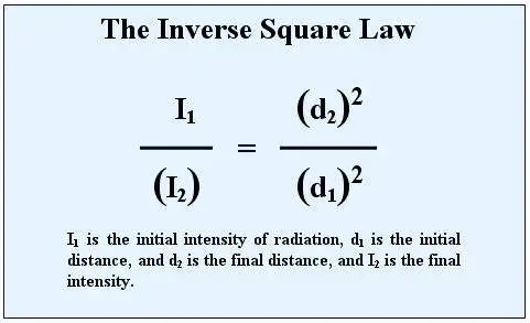
Distance and Dose - Inverse Square Law
when distance from source increased, intensity decreases
works off of concept called the inverse square law stating that the intensity of radiation is inversely proportional to the square of the distance between the x-ray tube and IR
to minimize exposure as tech stay 6 ft away
Ex/ if rad dose to pt was 10 millisieverts (mSv) at 100 cm, what would the dose be if distance was reduced to 76 cm?
Distance and mAs - Direct Square law
direct square law and exposure maintenance formula maintains the mAs (technique) needed to maintain receptor exposure at varying SID’s
new mAs for new SID to maintain exposure
mAs varies directly w/ the square of the distance
If distance increase 2x (farther away) = 40” to 73”, mAs needs to be increased by 4 times so mult by 4
if distance decreased by ½ (closer) = 72” to 40”, mAs needs to be decreased about 4 times do divide by 4
Technique Setting
techs use combo of settings of mAs/kVp or uses automated system called automatic exposure control (AEC); mAs is combo of mA and secs/time; when using AEC, removes option for tech to set exposure time/total mAs
Automatic Exposure Control (AEC)
devices that can assist the tech in making consistent rad images from pt to pt regardless of size/pathology
techs select kVp, mA + appropriate AEC chambers/photocells (which determines the time)
AEC units found in table/wall bucky (NOT in IR)
ionization chamber will determine exposure time/terminate exposure when part is fully penetrated
Minimum response time = 1 millisecond
AEC Advantages
less repeats, decreased repeat exposure due to underexposure, decreased pt exposure w/ less repeated images, increased dept. efficiency w/ less repeated images
AEC Ionizing Chamber Pattern (Photocells) (2)
3 cell format (most common) = 2 outer cells, 1 center cell
5 cell format = adds two lower cells (looks like the 5 on dice)
Ionizing chambers
interacts w/ remnant beam/exit rad before it reaches the IR; air in the chamber is ionized + electric charge that is proportional to amount of rad created
AEC Choices
anatomy over cells + cells selected matter
ex/ PA chest error = if you are imaging a chest and are interested in the lungs which are less dense, if you activate center cell, the image will be overexposed since the AEC is detecting time needed for the thicker vertebrae and not the thinner lungs
ex/ Lateral chest AEC error = if two outer cells activated which is over the lungs and not the denser vertebrae, this will result in underexposure
Density settings (AEC)
used when the ionization chamber configuration is not producing the desired image
Commonly -1 & +2 options available on equipment
+1 density increases exposure time; -1 density decreases exposure time
Ex/ if the lung fields are too dark, a decrease in density is desired even if the correct cells were used
AEC Backup timer
used to prevent overexposure to the patient if one of the aec components were to fail
Should be set at 150-200% of the expected exposure time
If backup timer is set too short, an underexposure will result
Maximum allowable mAs is 600mAs
How Factor Changes affect AEC
Inverse relationship:
mA INCREASE = AEC/exposure time DECREASES
kVp INCREASE = AEC/exposure time DECREASES
Direct relationship:
As SID INCREASES = AEC/ET INCREASES
Density INCREASES = AEC/ET INCREASES
Disadvantages to AEC
Technologists must be accurate when selecting cells
Large amounts of fluid in body part can affect accuracy of AEC (ex. Pleural effusion)
Prosthetic devices centered over cell can result in overexposure
Not enough collimation allows for too much scatter to reach the IR (can result in underexposure)
Anatomic program radiography (APR)
radiographic technique chart programmed into x-ray console
machines will use part selection or an image to identify area being radiographed, then a suggested technique of kVp and mAs appear
settings can be overridden when necessary.
Exposure index/range (EI)
exposure indicator (EI number) serves as an indicator of the relative exposure used for a particular exam
Computed Radiography (CR) vs. Digital radiography (DR)
Computed Radiography (CR) = sensitivity, or S number. Has inverse relationship with technique:
High number = underexposure (over 600)
Low number = overexposure (under 75)
Digital radiography (DR) = EI, DEI, REX number; direct relationship with technique
High number = too much technique
Low number = not enough
Quantum mottle vs Saturation
Quantum mottle = underexposure from not enough mAs; Quantum noise; Image noise; Grainy appearance
Saturation = severe overexposure from technique being too high; receptor was saturated w/ photons so soft tissue differentiation lost; soft tissue looks “burnt out”
Gross Overexposure error
demonstrated as missing data points on a digital radiograph; overexposure creates condition called data droop
Focal spot size
used to control spatial resolution (detail)
most current equipment has the correct focal spot pre-selected on the console when the body part is chosen
Small focal spot size vs Large focal spot size
Small focal spot size = produce less blurring and better visibility of detail
Ex./ Extremity work, ribs
Large Focal spot size = has greater heat dissipating capacity
Ex./ Chest, abdomen
Field of view (FOV)
size of your light field, ideally only kept open to the size of the part being imaged and controlled by the collimator
Increase beam restriction: increase collimation = decrease field of view = smaller light field
Increase field of view: decrease collimation = larger light field
Technique charts
for each anatomic part there is an optimum kVp to penetrate that thickness of bone (mAs is based on part thickness or pathological condition)
If they have more mass you need more mAs
Weight or size cannot be the only consideration
each x-ray equipment will have a separate chart
CR vs DR
Manufacturer designs chart
Newer equipment = less does = lower mAs values
Anatomically programmed radiography (APR) suggests technique when you select body part
Contrast Media (barium) 15% rule
techniques will need to be adjusted for the addition of contrast media, the most common one being barium
when kVp increases that high we will need to use the 15% rule
Ex. when barium is used for an abdominal examination, the kVp must be increased to 110,109 depending on the equipment settings
15% rule
states that when the kVp increases by 15%, it is equal to doubling the exposure (or using 2x the mAs); must cut mAs in half so not to double the exposure
Upper GI abd technique (stomach filled with barium) = 10 mAs @ 109 kVp
Ex. scout abd technique = 20 mAs @ 80 kVp
Primary x-ray beam
refers to the x-rays that are produced by x-ray tube and strike the patient; made up of either characteristic or bremsstrahlung or both
Remnant beam
remaining beam after it exits the patient; made up of primary and secondary radiation
Scatter radiation
type of secondary radiation that occurs when the beam intercepts and object, causing x-rays to be scattered
Beam quality
energy of the x-ray photons
Determines ability to penetrate
Determined by kVp setting
Beam quantity
number of x-ray photons
determined by mAs
Frequency
number of waves; the the energy of the x-ray - the higher the frequency
Higher kVp = higher energy
Higher kVp = higher frequency
Wavelength
distance between two successive peaks(tops of waves)\
Higher kVp = shorter wavelength
Low kVp = longer wavelength (less energy)
Areas for critique (3)
Anatomical positioning and accuracy (anatomy of interest, rotation/tilt, collimation, pathology demonstrated)
Technical factor accuracy (receptor exposure, contrast)
Sharpness of detail (spatial resolution, distortion, motion unsharpness)
Photographic factors vs. Geometric factors
Photographic factors = receptor exposure/contrast
Geometric factors = spacial resolution/distortion
Receptor Exposure
amount of radiation that reaches the image receptor; primarily controlled by mAs
Secondary controllers: kVp (direct relationship), SID, beam restriction (collimation), patient size, anode heel effect, grids, filters.
Higher mAs means higher receptor exposure
Collection of primary and secondary radiation.
Patient Size
increase in patient size = higher absorption of the beam into the tissue
less photons will reach the IR = less receptor exposure
Collimation (2)
Increase collimation = decrease field of view (smaller light)
Decrease collimation = increase field of view (larger light field)
Digital image contrast
controlled by look-up-table (LUT) which is a processing algorithm built into equipment that tech does NOT control (not controlled by kVp)
Size distortion vs Shape distortion
Size distortion = magnification of a part
Primarily controlled by OID; (OID is “key” to magnification)
Second controller = source to image distance (SID)
SID can be used to compensate for increase in OID (for every 1” increase in OID, a 7-8” increase in SID should be used to compensate
Shape distortion = shape distortion will either be elongation or foreshortening of the part
Elongation results from angling the tube and IR; can be helpful in certain images such as calcaneus image
Foreshortening results from angling of body part
Motion sharpness
distortion from object, tube, receptor due to movement during exposure
Voluntary motion vs. involuntary motion
Voluntary motion = motion patient can control; communication and clear instructions are best way to minimize
Involuntary motion = motion the patient cannot control; Ex./ Cardiac motion