Chapter 4: Data Elements, Signal Elements
 Call Kai
 Learn
Learn Practice Test
 Spaced Repetition
 Match
Match Flashcards
 Knowt Play
1/83

There's no tags or description
Looks like no tags are added yet.
Name | Mastery | Learn | Test | Matching | Spaced | Call with Kai | Chat |
|---|
No analytics yet
Send a link to your students to track their progress
84 Terms
What is a data element?
A data element is the smallest unit of information being transmitted. For binary data, one data element is one bit.
How many data elements are in the following:
1011
4 data elements
What is a signal element?
The shortest unit of a digital signal used to carry one or more data elements.
What is another name for a signal element?
Symbol/Signal state
If 1s are represented by High Voltage and 0s are represented by low voltage, how many signal states do we have?
2 signal states.
Distinguish between a data element and a signal element
Data element = what needs to be sent logically (bits)
Signal element = what needs to be sent physically (signal)
Why not just have one signal element for every bit?
Because it is not the most efficient.
What is r?
r = the number of data elements/the number of signal elements
It’s a ratio that tells us how many bits are carried by each signal element, on average.
Suppose we want to send: 1011
Our encoding produces 2 signal elements to represent every 1 bit.
What is r?
This means that 1011 is represented by:
1 = 2 signals
0 = 2 signals
1 = 2 signals
1 = 2 signals
Total: 8 signals
Therefore: r = 4 data elements/8 signal elements =1/2
r = 1/2
Suppose one signal element can represent 2 bits.
What is r if we would like to send 1011?
This means that 1011 is represented by:
10 = 1 signal
11 = 1 signal
Therefore r = 4 data elements/2 signal elements = 2
r = 2
How can one signal element represent two bits?
Each signal element can represent a set of 2 bits.
00 → Signal State 1
01 → Signal State 2
10 → Signal State 3
11 → Signal State 4
Suppose our data is: 00 10 11 01
And our line encoding method produces 2 signal elements to represent 1 bit.
What is r?
This means that 00 10 11 01 is represented by:
0 = 2 signals
0 = 2 signals
1 = 2 signals
0 = 2 signals
1 = 2 signals
1 = 2 signals
0 = 2 signals
1 = 2 signals
total: 16 signals
r = 8 data elements / 16 signals = 1/2
r = 1/2
Suppose our data is: 1011
And our encoding produces 4 data elements per 3 signal elements
Find r.
1011 means that it is represented by:
1011 = 3 signal elements
Therefore, r = 4 data elements / 3 signal elements = 4/3 = 1.3333
r = 1.3333
What is Data Rate/Bit Rate?
Data Rate/Bit Rate is the number of data elements (or bits) transmitted per second. It is measured in bps (bits per second).
Data Rate = data elements / second
What is Signal Rate/Baud Rate?
Signal Rate = signal elements / second
Signal Rate = the number of signal elements being transmitted per second. It is measured in baud.
What variable do we use to represent Bit Rate/Data Rate?
N
If a system transmits 100,000 bits every second, what is N?
N = Data Rate
N = 100,000 bps or 100 kbps
What variable do we use to represent Baud Rate/Signal Rate?
S = Signal Rate
What does the Baud unit actually represent?
Baud = represents the number of signal elements per second
Are bits per second and Baud the same thing?
Not necessarily. Bits per second measures bits, baud measures signal elements.
While they might sometimes be the same value, other times, they might be different, and this is because of r (our ratio of data elements to signal elements).
What is the basic formula for Signal Rate?
S = N/r
S = the number of signal elements per second (measured in Baud)
N = the bit rate/data rate (measured in bps)
r = data elements carried per signal element (bits/signal)

Suppose r = 1 and N = 1000bps. Find the Baud rate.
S = N/r
S = 1000/1 = 1000 Baud.
In this case, 1000 Baud corresponds to 1000 bps (1000 signal elements per second for 1000 bits per second)
Suppose N = 1000 bps and r = 2. Find the Baud rate.
S = N/r
S = 1000/2 = 500 baud.
In this case, 500 Baud corresponds to 1000 bps (500 signal elements per second for 1000 bits per second)
Suppose N = 1000 bps and r = 1/2. Find the Baud rate.
S = N/r
S = 1000 bps / 0.5 bits/signal = 2000 Baud
In this case, 2000 Baud corresponds to 1000 bps (2000 signal elements per second for 1000 bits per second)
Why would we want a high Data Rate?
Because a higher data rate means more bits are transmitted per second.
For example: 100 Mbps can transmit information faster than 10 Mbps.
Why do we want a low Signal Rate?
Because a lower signal rate means a lower bandwidth requirement. High signal rates typically require lots of bandwidth, and we want a lower bandwidth requirement because bandwidth is costly/expensive in the real world.
In data communications, what is our goal with data rate and signal rate? What do we want to maximize? What do we want to minimize?
The goal is to increase data rate while also decreasing signal rate.
This may sound contradictory, because it means we’re trying to send more bits by transmitting fewer signals; However, this is something that can actually be achieved, simply by increasing the amount of information represented by a signal element; or in other words, increasing r.
Which is more efficient? System A or System B, and why?
System A:
r = 1. To transmit 1000 bps we need 1000 baud.
System B:
r = 2. To transmit 1000 bps we need 500 baud.
System B is more efficient because it requires fewer signal elements in order to transmit the same number of bits per second.
What is the formula for calculating the average signal rate/average baud rate?
Savg = cN/r
Savg = average baud rate/signal rate (measured in baud)
c = case factor, a constant value already given to you in the question you need to solve
N = bit rate/data rate (measured in bps)
r = the # of bits / signal

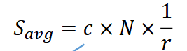
Why do we suddenly need another formula for Signal Rate with c in it?
This formula is necessary because it gives you the ACTUAL Signal Rate, while the other, more simplified formula: S = N/r doesn’t take into account a couple of big factors that impact the signal rate.
Two factors that impact the actual number of Signal changes is the pattern of bits being transmitted, and the specific line coding scheme.
For example:
000000 might produce a different number of signal changes than 010101, even though they both contain 6 bits. This is because they have different bit patterns.
So knowing bit rate and r isn’t enough to accurately tell us what the Signal Rate is.

What does c, the case factor actually mean in the following equation?
The case factor, c, is a constant value (always given to you in the question), that accounts for the specific line coding scheme/data pattern case used when calculating signal rate.
It has no units.
When discussing Signal rate, what is best case, worst case, and average case?
Best Case = The minimum signal rate
Worst Case = The maximum signal rate
Average Case = The typical/average signal rate.

Where do we get the value of c from for the following equation?
You will be given c (the case factor) in the question.
A signal is carrying data in which 1 data element is encoded as one signal element. If the bit rate is 100 kbps, what is the average baud rate if c = 1/2?
Converting the data rate: 100 kbps to bps:
we know that 1 kbps = 10³ bps
so: 100 kbps x 10³ bps/1 kbps = 100000 bps
Calculating the average baud rate/signal rate:
Savg = 0.5(100000) / 1 = 50000 baud
Converting baud to kbaud (optional):
50,000 baud x 1 kbaud / 10³ baud = 50 kbaud
Answer: 50,000 baud or 50 kbaud
In this question, if r = 1, shouldn’t 100,000 bits require 100,000 signal elements?
A signal is carrying data in which 1 data element is encoded as one signal element. If the bit rate is 100 kbps, what is the average baud rate if c = 1/2?
No, not at all. This is the reason why we introduced c. If we only look at things using the simple equation: S = N/r, then it may seem like 100,000 bits should require 100,000 signal elements.
However, as we discussed earlier, S = N/r does not take into account the other factors that impact Signal Rate, such as data pattern and line encoding scheme. So we can’t accurately say that 100,000 bits requires 100,000 signals. We have to use Savg = cN/r to determine what the actual Signal Rate would be given a certain number of bits per second.
What does line coding scheme refer to?
A line coding scheme is the set of rules that determines how bits are represented as voltage levels over time.
It might define things like:
How many bits each signal can represent
How many signal elements it needs to transmit per second
How much bandwidth that signal requires
Whether there is baseline wandering
Whether the receiver remains synchronized…etc.
But you don’t have to memorize all these points.
How does Signal Rate relate to Frequency?
As the Signal Rate increases, the Frequency increases.
For example, if the Signal Rate is 1000 baud, this means we’re transmitting 1000 signal elements per second. If we increased this to 10,000 baud, we’re now squeezing 10 times as many signal elements into one second.
This means that each signal element lasts for a much shorter amount of time, and therefore the waveform changes very quickly, meaning a higher frequency.

A high signal rate means _________ bandwidth is required.
more
In the context of signals, what is bandwidth referring to?
Bandwidth is the range of frequencies available to a signal channel. Recall: bandwidth = highest frequency - lowest frequency.
The greater the bandwidth available to us, the __________ the range of frequencies available to create a transmitted signal.
greater
Is it true that a digital signal technically has infinite bandwidth?
Yes, theoretically, perfect digital signals require infinite bandwidth. If we actually had perfectly sharp, instantaneous transitions between levels in a digital waveform, then we would need arbitrarily high frequency components, and therefore infinite bandwidth.
Remember: In order to create these sharp transitions, we layer multiple different waveforms with larger and large frequencies to approximate the square shape used to represent binary 0s and 1s.

In real life, do digital waveforms actually have infinite bandwidth?
No. This is because in real life, we don’t actually need the perfect waveform. It’s fine if we receive a smoother waveform so long as the 0s and 1s can still be distinguished.
What is actual bandwidth and effective bandwidth?
Actual bandwidth = refers to the theoretical idea that a perfect digital waveform should have an infinite range of frequencies.
Effective bandwidth = refers to the finite range of important frequencies that are needed to reproduce a signal accurately enough for successful communication.
What is the relationship between Baud rate and Bandwidth?
Baud rate/Signal Rate refers to how many signals are transmitted per second. Bandwidth is the range of frequencies in a given channel/signal. As the Signal rate increases, the frequency increases, and therefore the Bandwidth also increases.
For example:
If you originally had frequencies going from 0 to 300 Hz, your bandwidth would be: 300-0 = 300 Hz.
If you then increased your maximum frequency to 500 Hz, your bandwidth would be: 500-0 = 500 Hz. This means bandwidth increases when frequencies increase. And we know that frequencies increase when we have a higher Signal Rate.
What is the formula for required Bandwidth?
B = cN/r
B = Bandwidth (measured in Hz)
c = Case factor
r = the number of data elements/signal
N = the bit rate/data rate (in bps)
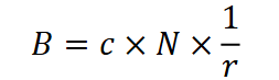

In this equation, what happens to Bandwidth if we increase the bit rate?
If we increase the Bit Rate, N, the bandwidth increases.

In this equation, what happens to Bandwidth if we increase r?
The bandwidth decreases.
Suppose N = 200 kbps, r = 2, and c = 1/2. Find the required bandwidth. Convert 200 kbps to bps.
Interpret what the result means.
B = cN/r
Convert 200 kbps to bps:
200 kbps x 10³ bps / 1 kbps = 200,000 bps
Calculate the Bandwidth:
B = ½ (200,000) / 2 = 50,000 Hz
Convert Hz back to kHz (Optional):
50,000 Hz x 1 kHz / 10³ Hz = 50 kHz
Answer: 50,000 Hz or 50 kHz
This means that transmitting this given data would require a range of 50,000 Hz (or 50 kHz).
Why does the receiver of a digital signal need a baseline?
Because the receiver needs a reference point to distinguish between higher or lower states of an incoming signal and interpret the signal.
For example, a receiver can’t always assume that the incoming signal will always be exactly +5V or -5V because signals can become distorted over time. So while the sender might transmit a 5V signal, it will probably arrive as 4.4 V when it reaches the receiver. The receiver needs a baseline value to be able to tell which amplitudes represent higher states, and which represent lower states.
How does the receiver of a signal calculate the baseline?
Originally, the receiver assumes that the baseline is 0 V.
Then, the receiver observes the received signal, and calculates a running average of amplitudes/signal measurements (ex. the average of +4.5, -4.7, +4.8, -5.0).
Based on that average, the baseline either moves up or down from 0 V.

What is baseline wandering?
Baseline wandering is when the receiver’s estimated reference point drifts too far off from its useful reference position because the received signal has remained biased towards one level for too long.
For example:
Imagine the receiver just continually received a string of 1s. This means they would receive: 5V 5V 5V over and over again, therefore, this will shift the baseline/running average significantly upwards.

Is baseline wandering a problem?
Yes, because if the reference point has significantly shifted to one side, it becomes harder to distinguish between the intended states.

What causes baseline wandering?
A long string of 1s or 0s.
Let’s say the receiver is perfectly capable of distinguishing between a 0 and a 1.
Then what’s the problem with receiving three consecutive 1s?
For example: 1 1 1 1
The problem is that there’s no obvious transition between the three ones, because they’re all represented by the same voltage (for example, 5V). If the receiver just receives a continuous amplitude of 5 V, it would have no way of knowing whether the consecutive string of 1s represents 111 or 11 or 1111 or 11111… and so on.

So how is the receiver actually able to distinguish between consecutive bits?
It calculates how long a bit lasts, which is otherwise known as bit duration, and determines the number of bits in an interval based on that time.
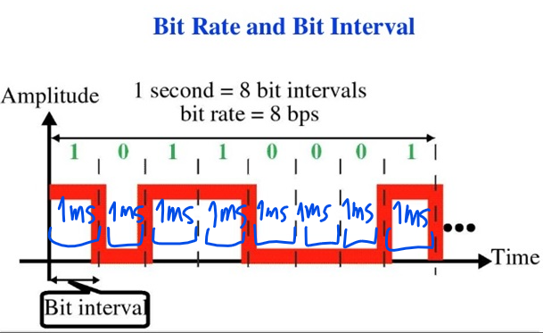
Recall: What is the formula for Bit Duration?
Bit Duration = 1 / Bit Rate
If the Bit Rate is N = 1000 bps, calculate the bit duration.
Explain how the receiver uses this information to distinguish between identical consecutive bits.
Bit duration = 1 / 1000 bps = 0.001 s
Convert to ms (optional):
0.001 s x 10³ / 1s = 1ms
Now it knows that each bit takes about 1ms. So if it receives a continuous reading of 5V (because of a long string of 1s), it knows that after approximately 1ms, it encounters another bit.

How does the receiver keep track of time? What about the sender?
Both the sender and the receiver each have their own internal clocks to help keep track of time.
Optional Question: A clock seems like such an abstract concept. What kind of clock are we referring to?
The clock is actually just a hardware component/circuit that is built out of quartz crystal and oscillates at regular intervals to keep track of individual bits.

What happens if the receiver’s clock is slightly faster than the sender’s clock?
Errors start to accumulate and the two become very unsynchronized. As a result, bits are misinterpreted.
For example:
If the receiver’s clock thinks a bit lasts 1ms, and the sender’s clock thinks a bit lasts 1.2 ms, the difference might be minor, but the errors accumulate over time. Suddenly, the receiver’s clock is farther and farther ahead of the sender, to the point where the receiver is dividing the waveform into the wrong intervals, and therefore misinterpreting bits.
This means that the sender might send: 10110001
and the receiver will misinterpret those bits as 110111000011
Why might these two clocks become unsynchronized?
Because each clock is a separate physical device, and it’s possible that manufacturing issues might make one run faster than the other.
What is self-synchronization?
Self synchronization is the ability for the receiver to recover and continually fix its bit timing by introducing transitions at specific moments within the transmitted signal.
This property is controlled by the line-coding scheme (the rules that define bit transmission).
Give an example of self synchronization.
One example could be transitioning the voltage halfway through the transmission of a single bit.
Let’s say 1s are represented by 5V and 0s are represented by -5V.
The line coding scheme might define a rule which says that a transition should occur in the middle of a bit.
For example, in the middle of representing bit 0, transition from -5 V to 5V. Then, in the middle of representing bit 1, transition from 5V to -5V. So if a bit takes 1ms, at the 0.5ms mark, the transition will occur. Note that after the transition, it returns back to its normal state used to represent that bit. Ex. So this means to represent bit 0: -5V → 5V → -5V.
If the transition happens later or earlier than expected, this will signal to the receiver that its internal timing is slightly off, and it can use that information to adjust its timing estimate.
Note: It doesn’t always have to be a middle transition; It could be any rule, any transition to signal to the clock that it needs to adjust its timing. This is simply an example.
The receiver’s clock is 0.1 percent faster than the sender’s clock. How many extra bits per second does the receiver receive if the data rate is 1 kbps? How many if the data rate is 1 Mbps?
The receiver’s clock is 0.1% faster (calculate as decimal): 0.1 / 100 = 0.001
Convert to bps:
1 kbps x 10³ bps / 1 kbps = 1000 bps
1 Mbps x 106 bps / 1 Mbps = 1,000,000 bps
For kbps:
If the receiver’s clock is 0.1% faster, we calculate 0.1% of 1000:
1,000 bps x 0.001 = 1 bit
Therefore, during the time the sender sent 1000 bits, the receiver’s clock counted enough intervals for 1000 + 1 = 1001 bits. So the discrepancy is 1 bit.
For Mbps:
If the receiver’s clock is 0.1% faster, we calculate 0.1% of 1,000,000:
1,000,000 × 0.001 = 1000
Therefore, during the time the sender sent 1,000,000 bits, the receiver’s clock counted enough intervals for 1,000,000 + 1,000 = 1,001,000 bits. So the discrepancy is 1,000 bits, or 1,000 extra bits per second.
What is NRZ?
NRZ is a line coding scheme that stands for Non Return to Zero.
The NRZ scheme just states that a signal does not need to return to 0V (the neutral or rest state) between bits.
For example:
If a bit is represented by 5 V, it can stay there for the whole bit. It is not required to return to 0 V at the end of that bit.
What is NRZ-L?
NRZ-L stands for Non Return to Zero - Level. It is a subset of the NRZ line coding scheme which states that the voltage LEVEL itself represents the bit.
The rule for it is:
+V = 0 and -V = 1.
What would the voltage levels be for 0000 according to the NRZ-L line coding scheme?
+V +V +V +V
Remember:
The rule for it is:
+V = 0 and -V = 1.
What is NRZ-I?
NRZ-I stands for Non Return to Zero - Invert. It is also a subset of the NRZ line coding scheme.
The rule for it is:
0 = do not change voltage
1 = invert/change voltage
Suppose we want to send 10110 and the signal currently happens to be -V. Encode these bits using NRZ-I.
Answer:
+V +V -V +V +V
Remember:
We start at -V.
The rule for it is:
0 = do not change voltage
1 = invert/change voltage
Why are they all called NRZ?
Because none of these line encoding rules requires the signal to return back to a neutral 0 state at the end of the bit.
What is Manchester Encoding?
In Manchester Encoding, every bit is divided into two halves, and there is a voltage transition in the middle.
Why does Manchester deliberately create that transition in the middle?
Because it supports self-synchronization.
This is something NRZ lacks. In the NRZ line encoding scheme, you could potentially have an entire period of just a single constant voltage where the clock timing could become misaligned.
Because the voltage changes contain an equal positive and negative contribution, which cancel out. This avoids the strong DC/baseline problems that happen when a signal stays on one side for too long.
+V-V / 2 = 0
What is Differential Manchester Encoding?
In differential Manchester, every single bit must have a transition in the middle for synchronization, and what happens at the start of the bit tells the receiver whether the data bit is a 0 or a 1.
The rule for the start of the bit is:
If it is a 0, there is a transition at the beginning
If it is a 1, there is NO transition at the beginning.
Suppose the signal is currently at +V and the next bit is 0.
Write the Differential Manchester encoding for this.
We start at +V, and the next bit is 0.
Answer:
+V → -V → +V (middle) → nothing yet because what happens here depends on the next bit
Remember:
The rule for the start of the bit is:
If it is a 0, there is a transition at the beginning
If it is a 1, there is NO transition at the beginning
The rule for the middle is that there is always a transition.
Suppose the signal is currently at +V and the next bit is 1.
Write the Differential Manchester encoding for this.
Answer:
+V → +V → -V (middle) → nothing yet because what happens here depends on the next bit
Remember:
The rule for the start of the bit is:
If it is a 0, there is a transition at the beginning
If it is a 1, there is NO transition at the beginning
The rule for the middle is that there is always a transition.
What is Bipolar AMI?
A line coding scheme which says that every time a 1 occurs, you want to alter its polarity. But as soon as you encounter a 0, go to 0V.
The rule for it is:
Every time a 1 occurs, alter polarity.
When a 0 occurs, go to 0V.
What does Unipolar, Polar, and Bipolar mean? What are these terms referring to?
These are all terms describing the features of different line encoding schemes.
Unipolar = means the nonzero signal level only exists on one side of 0. For example: 0, +5V
Polar = uses voltages on both sides of 0. This means the signal can only be positive or negative, but never zero. For example, +V and V. (Think: It’s polarized but never neutral)
Bipolar = has only 3 levels: +V, 0, -V
Classify the line encoding schemes based on the terms: Polar, Unipolar, Bipolar.
Manchester & Differential Manchester: Polar
NRZ-I and NRZ-L: Polar
Regular NRZ: Unipolar
Bipolar API: Bipolar
Summarize the rules for:
Regular NRZ
NRZ-L
NRZ-I
Bipolar AMI
Regular NRZ: A signal does not need to return to 0V after completing a bit.
NRZ-L: A signal has bits represented by its voltage level, where +V = 0 and -V = 1.
NRZ-I: A signal inverts/changes the voltage when the bit is 1, and does not change the voltage when the bit is 0.
Manchester: There is a voltage transition in the middle of the bit.
Differential Manchester: There is a voltage transition in the middle of the bit and the start of the bit indicates whether it is a 0 or a 1. If it’s a 0, there is a transition at the beginning, if there’s a 1, NO transition at the beginning.
What is a DC Component?
A DC component is the mean, or average amplitude of a signal over time.
If you have a simple signal of +5V that never changes, what is its DC component?
Its DC Component is 5V.
We know this because DC component refers to the average amplitude of a signal over time.
Since 5V is the only amplitude, it is also the average.
In a digital transmission, the receiver clock is 0.2 percent faster than the sender clock. How many extra bits per second does the receiver receive if the data rate is 1 Mbps?
We know that the receiver is 0.2% faster than the sender clock:
Convert this to a decimal:
0.2/100 = 2 × 10⁻³
Convert Mbps to bps:
1 Mbps x 106 bps / 1 Mbps = 1,000,000 bps
Find 0.2% of 1,000,000 bps:
(2 × 10-3) x 1,000,000 bps = 2000 bits
Answer: 2000 more bits per second (bps)
An analog signal has a bit rate of 8000 bps and a baud rate of 1000
baud. How many data elements are carried by each signal element?
How many signal elements do we need? Assume c = 1 and each signal
element corresponds to a signal level.
For Question 1, we know:
N = 8000 bps
Savg = 1000 baud
c = 1
Substitute and solve for r:
Savg = cN/r
1000 = 1(8000)/r
1000 = 8000r
r = 8000/1000
Answer: r = 8 bits/signal element
Question 2 is poorly worded. What it means to say is: if our signal element represents 8 bits, how many different possible signal levels do we need?
The formula is 2# of bits = different bit patterns
Answer: 28 = 256

The figure below shows the encoding of a bit sequence using two
different line coding schemes. Indicate the category (unipolar, polar,
bipolar) of the line coding schemes used in (a) and (b). Give the
reasoning for your answer.
a) Polar, because it only includes a positive and negative state, without ever reaching 0 V.
b) Bipolar, because it includes a positive and negative state, as well as a state of 0 V.
Recall what each of these terms mean.
Unipolar = on one side of the 0, for example: 0V and 5V
Bipolar = all 3 states, -5V, 0V, and 5V
Polar = only -5V and 5V, not 0V