BME 311 Lecture 6
 Call Kai
 Learn
Learn Practice Test
 Spaced Repetition
 Match
Match Flashcards
 Knowt Play
1/36

There's no tags or description
Looks like no tags are added yet.
Name | Mastery | Learn | Test | Matching | Spaced | Call with Kai | Chat |
|---|
No analytics yet
Send a link to your students to track their progress
37 Terms
practicalities of clinical environment - cost
purchase
operation - trained and licensed technologist
consumables - contrast or tracer
maintenance
practicalities of clinical environment - time
acquisition
processing
only enough time to get “sufficient” accuracy
noise
fundamental randomness in data/images
different data even if exact same experiment were repeated
raw data (“counts”) often “poisson” whereby stdev = sqrt(mean
background
signal that is not of interest - real or artifact
reduces contrast of feature you are interested in
can also have noise in it
contrast
ability to distinguish different intensities
often ration of signal to background
“count”
detection of a specific (integer) number of x-rays
projection imaging
acquisition of 2D (i.e. 2D) image of patients 3D anatomy
i.e. total beam attenuation along the line Z

what are we measuring in radiography
counts at an image point relate to attenuation along line connecting to focal spot
counts proportional to exp(-mu*x)
what is mu varies along line? break into line segments dx:
counts proportional to exp(-mu1*dx)*exp(-mu2*dx)*exp(-mu3) = exp(-[sum of mu values]*dx)
basic geometric principles
two triangles similar: a:A = b:B = c:C = h:H
magnification (M) = I/O = SID/SOD
I = image size
O = object size
SID = source to image distance
SOD = source to object distance
what about imperfect focal spot
extended source - think of it as a number of different points
geometric blurring of objects occurs
reduce OID to reduce blurring, but does it really help since this also reduces magnification? what really matters is to minimize f/I
f/F = g/G = OID/SOD = (SID-SOD)/SOD
= SID/SOD-1 = M - 1
so f = F (M-1)
Remember I/O = M, so I = M O
Ratio f/I = F/O (M-1) / M
Or f/I = F/O * (1 - 1/M)

closer detector produces sharper image
assuming detector has sufficient resolution

which condition is for compressed breast imaging
very small focal spot is possible = small F, so small blurring
need high resolution detector to acquire image
many optical technologies exist for imaging
easy to detect in small pixels
mature - commercial applications for >100 years
few detectors for x- or gamma-rays
much more penetrating
not many interactions in optical detectors
scintillator (phosphor)
special material in which photoelectric/compton effect from x-ray interaction produces optical photons
convert an x-ray photon into many optical photons
“intensifying screen” contains. scintillator crystals
want high absorption and conversion efficiencies
absorption efficiency aka QDE (Quantum Detection Efficiency (%))
= fraction of incident x-rays that interact with detector and thus are deleted
efficiency of detector is proportional to 1 - exp(-mu*x)
determines radiographic “speed” - how long an exposure us needed
i.e., high speed = high absorption efficiency = short exposure time

total conversion efficiency
fraction of energy deposited by x-ray absorption that is converted into optical photons
depends on the intrinsic properties of phosphor
conversion efficiency
fraction of absorbed energy emitted as light
% converted to photons
e.g. Gd2O2S – conversion efficiency 15% - emits green light – 2.7 eV/photon
What is the number of green light photons produced by absorption of 50keV x-ray photon?
50000 x 15% = 7500 eV
7500 / 2.7 ~ 2800 green photons
radiography detector types
analog: screen-film
digital: more modern, digitize earlier
computed radiography
CCD and CMOS
thin film transistor (TFT)
screen film cassette
cost
film can’t be reused
time
chemical developing takes time

intensifying screen function and geometry
two functions:
absorb incident x-ray
emit visible light - isotropically = in all directions
thicker → absorb more photons (i.e., more sensitive) → but reduced spatial resolution (due to more light spread)
use 2 layers:
preserve spatial resolution by keeping scintillator thin
compensate for lost detection efficiency by using 2 layers

digital imaging: multiple technologies
conversion from analog to digital at different points in the imaging process
digital imaging: computed radiography (CR)
partially digital
instead of screen+film, uses special phosphor that converts x-ray to long-lived excited electron states
computed radiography: principle of readout
A: x-rays are absorbed in the storage phosphor, electrons reach the conduction band
B: electrons are trapped in this high-energy state
C: red laser provides the trapped electrons to be excited, some of them will drop down to the valence band, emitting blue light during the transition
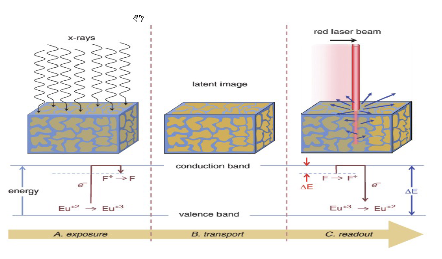
computed radiography
raster scan
once read out, ready for use again

first digital method: computed radiography
x-ray exposure, imaging plate, CR

computed radiography vs screen film
CR provides greater dynamic range
exposure is proportional to duration of x-ray pulse
which must be decided in advance by technologist
depends on size of patient, kVp, etc
can be incorrectly estimated
more tolerant of over/under exposure
retake due to overexposure or underexposure
cost
inconvenience
more dose

number of voxels, pixel exposure
resultant images

modern light sensors
silicon devices accumulate charge deposited by light
CCD = charge coupled device
~2.5 × 2.5 cm, 2048 × 2048 pixels
great resolution (microns)
but small and slower to read
CMOS
microchip technology
random access
expensive, can be noisier
modern light sensors challenges
pure crystalline silicon wafers
need large areas = expensive

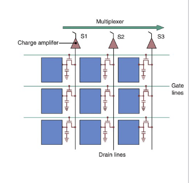
TFT arrays
thin film transistors
“hybrid” of CCD and CMOS
some simple circuitry
amorphous silicon = cheaper
large areas relatively cheaply
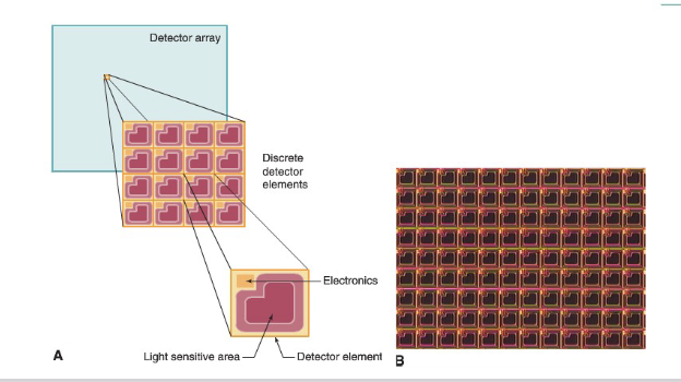
TFT arrays: indirect vs direct
indirect
scintillator to produce light
direct
no scintillator, no optical photons at all
x-rays interact directly in detector: e-hole pairs
amorphous selenium semiconductor (Se Z=34 vs. Si Z=14)
charge travels straight: thick does not hurt resolution
lower absorption efficiency than scintillator (mu of Si is not that high)

dual energy radiography
soft tissue, bone enhanced
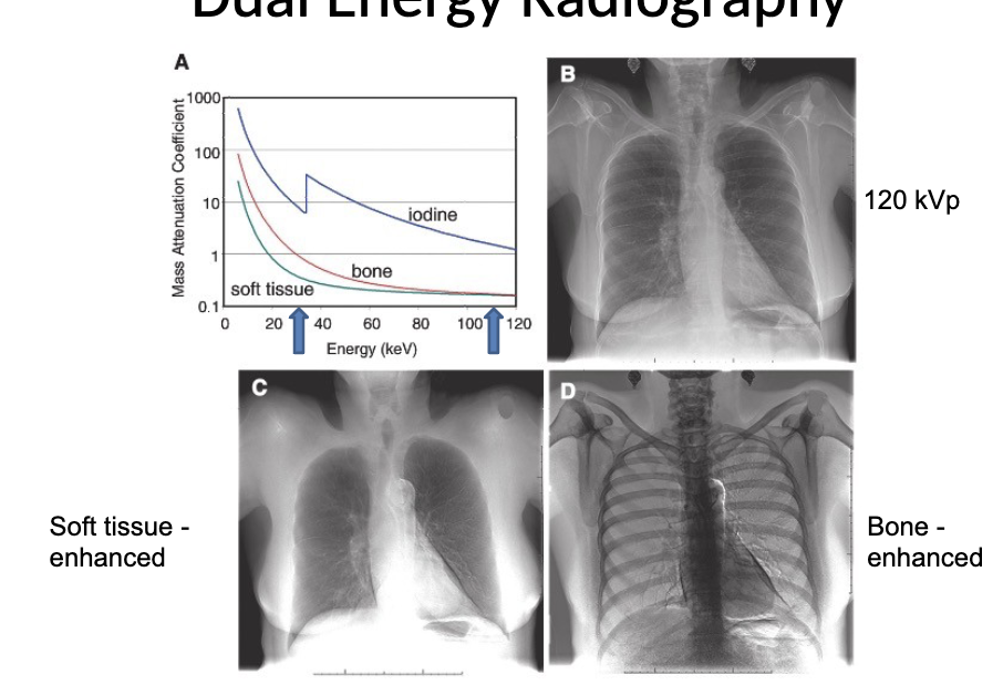
the anti-scatter grid
why is scatter bad?
tail, narrow lead walls = septa
aligned with focal spot
absorbs scattered radiation
H/W in diagnostic radiology can be >10
but work only at fixed distance between focal spot and detector
