x- ray production
 Call Kai
 Learn
Learn Practice Test
 Spaced Repetition
 Match
Match Flashcards
 Knowt Play
1/44

Earn XP
Description and Tags
to become familiar with the technological principles of x ray productions. explain the mechanist of x ray production, list the components of an x ray unit and explain the process of x ray generation, describe the physical characteristic of x ray systems, describe the thermal performance limitation, identify the different generator technologies.
Name | Mastery | Learn | Test | Matching | Spaced | Call with Kai | Chat |
|---|
No analytics yet
Send a link to your students to track their progress
45 Terms
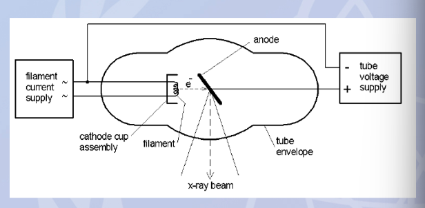
what is the basic principle of operation of x ray production?
1- a source of electrons is obtained from a heated filament (cathode)
2- electrons are accelerated towards an anode target by a high potential difference (up to 140kvp)
3- electrons interact with an anode composed of a metal with a high efficiency for conversion of electron energy into x ray photons
4- most energy transferred results in heat generation (~99%) with the remaining energy emitted as x ray radiation via a window or port
5- the quantity and energy of x ray emission is controllable by altering the operating parameters (kVp, mAs, etc)
x-ray tube housing assembly
provides the structural support to protect the tube insert
is filled with insulating oil which provides electrical insulation and heat removal
has expansion bellows to allow for oil volume expansion

how is cooling provided in the housing assembly?
by convection or forced heat exchangers
convection: the transfer of heat through the physical movement of liquid
forced heat exchangers: device that transfers thermal energy between two separated fluids or mediums using an external mechanical force-such as a fan, or pump, to move the liquids and speed up the transfer.
what is extra-focal radiation?
x rays produced at locations outside of the focal point of the x ray tube anode
lead shielding lines the inside of the housing to constrain leakage radiation to regulatory limits
what is an x-ray tube insert composed of and how does it work?
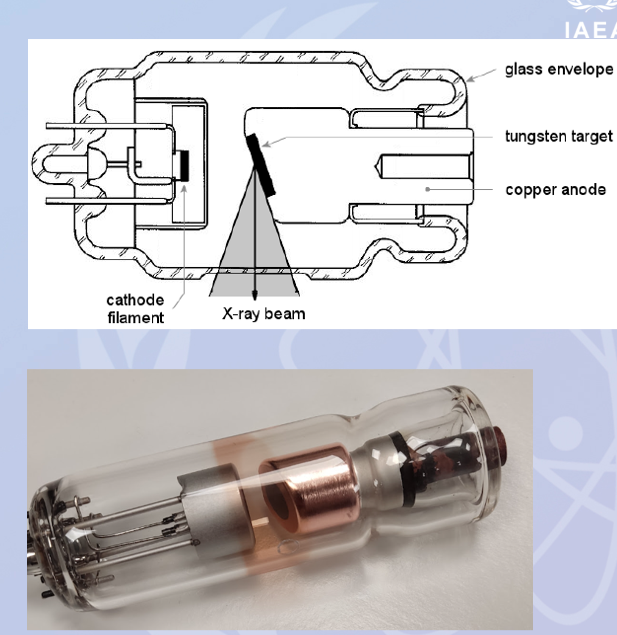
it comprises a heated filament (cathode), anode rotor assembly and support structures sealed in an envelope composed of glass, metal, ceramic materials
it maintains the required vacuum to allow free acceleration of electrons without collision of electrons with air/gas molecules
the x ray beam exists through a window in the envelope which has reduced thickness glass to minimize absorption
tubes used for low energy applications, such as mammography, typically incorporated a window composed of beryllium due to its improved transmission properties compared to glass
stationary anode
tubes that require only a low anode current or infrequence low power exposures (e.g. dentist unites) can have a stationary anode
a small tungsten insert serves as the target material and is embedded in a copper block to dissipate heat efficiently to the surrounding cooling medium
the maximum loading is limited by the anode temperature and temperature gradients due to the stationary focal spot on the anode
rotating anode
most x ray examinations require higher photon fluences than that achievable with stationary anodes due to thermal limitations and the potential for damage
the anode rotates during exposure thus effectively increasing the area bombarded by electrons to the circumference of a focal track
the energy is dissipated to a much larger volume as it is spread over the anode disc
this allows it to tolerate higher heat deposition and produce more x rays per unit time

what is the rotating anode construction with?
a tungsten target embedded in a molybdenum disc with a graphite heat sink attached to the rear of the disc
the anode is connected to a rotor and a spindle with a short stem and is typically composed of molybdenum with a low thermal conductivity to restrict the transfer of heat to the bearings

why is tungsten commonly used as an anode material?
it offers high bremsstrahlung yield and has other essential material characteristics
the spindle is supported by…
ball bearings to minimize friction. liquid metal bearings have also been developed to improve the continuous power rating of the tube
the rotating anode is attached to the rotor of an induction motor
electrical current in the stator windings outside of the tube envelope produce a driving magnetic field to provide rotational speeds of approximately 3,000 - 10,000 rpm

cathode
the cathode is the source of electrons within the tube and is composed of a spiral wound filament of 0.2-0.3 mm diameter tungsten wire. tungsten is used due to its high melting point (3370C) and can be combined with other materials to increase its electron emission efficiency.
typically, two filaments of differing sizes are available and offers differing image resolution and thermal performance capabilities
how does the cathode produce electrons?
the filament circuitry drives currents of up to 10A (<15V AC) through the filament. due to the electrical resistance this results in a heating effect and the release of electrons by thermionic emission. this current also determines the tube (anode) current which flows across the tube.
richardson’s law
thermionic emission of electrons increases with temperature
space charge
the cloud of electrons that encloses the filament
space charge effect
at 1000mA, no more electrons can be forced out of the filament.
because at high mA settings, the repulsive force of the space charge can exceed the repulsive force of the filament current, this can cause electrons from the space charge to return to the filament and inhibit additional electrons from joining the space charge
how do we minimize the evaporation of tungsten in the cathode?
the filament is permanently preheated to a temperature at which thermionic emission is negligible. during exposure it is raised to operational levels at a temperature of approximately 3370C
focusing cup
the focusing cup is a metal cup with an applied negative bias voltage that surrounds the filament and influences the electron beam width and improves resolution by restricting the electron beam distribution incident on the anode
without the focusing cup, the mutual repulsion of electrons leaving the filament will tend to spread and result in a broad beam striking the anode

unbiased focusing cup
the electrical supply to the filament and the focusing cup is shared, as we increase the current through our filament we increase it through the cup too
the current makes the focusing cup negatively charged and an electromagnetic field is formed around the cup and will repel the negative electrons and focus them down to a smaller area
the production of electrons and the amount of focusing are linked

biased focusing cup
an independent electrical supply exists for the focusing cup, which allows us to titrate the amount of negative charge for the focusing cup. this results in an even smaller focal area on the anode

grid cup
the focusing cup is so negatively charged that it prevents the electrons from being released from the filament

focal point
it’s the area on the surface of the anode where the electron beam interacts
the focal spout size is defined along the central beam projection
for good image resolution, a small focal spot size is desirable to minimize geometric blurring. to balance this requirement with the need for high heat dissipation, the line focus principle using an angled anode is used
focal spot size for general radiographic systems
0.6 to 1.2 mm
focal spot size for mammography systems
0.1 to 0.3 mm
focal spot size for interventional systems
0.4 to 0.8 mm
anode angle
anode angles typically range from 6 to 22 degrees for diagnostic x ray tubes
the radial dimensions of the focus size are determined by….
the filament coil diameter
effect of the focusing cup

the size of the focal spot of an x-ray cube…
is specified for the central beam in the x-ray field running perpendicular to the electron beam or tube axis
the actual focal spot size depends on…
the position within the field of view as shown


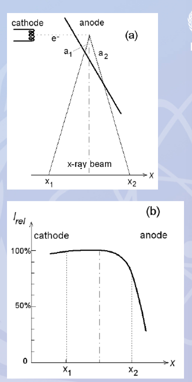
anode angle — heel effect
a variation in X-ray beam intensity along the longitudinal axis of the X-ray tube, making the beam stronger on the cathode side and weaker on the anode side
smaller anode angles result in smaller effective focus sizes but limit the field of view as the x ray beam is cut off by the anode
additionally self-absorption of x-rays at depth within the anode results in an inhomogeneous x-ray intensity across the field.
this is exploited in Mammography tubes to decrease the incident air kerma from the chest wall to the nipple, matching the decrease in organ thickness
what is the main limiting factor in the use of x-ray tubes?
thermal loading capacity
what is meant by thermal loading capacity?
significant temperature gradients at the surface of the anode can result in cracking and surface damage
heat conduction from the anode disc via the stem, the ball bearings, and bearing support is not very efficient
how can heat loading capacity damage be minimized?
by using a more ductile alloy e.g. tungsten/rhenium
some tube designs incorporate liquid gallium alloy bearings for improved thermal performance and continuous power rating of the tube
explain the diagram of a typical maximum permissible load versus time for a single exposure, constant current, 100k voltage and a 50kW tube
1- the maximum load is determined by mechanical stress in the anode material as a result of temperature gradients near the surface of the focal spot
2- the energy released raises the temperature to a maximum permissible level (2757C) for a few seconds thus limiting the maximum load
3- for longer exposures the heat conduction and heat capacity of the anode disc are important. Molybdenum is superior to Tungsten hence its use as a base material for the anode. Attached to the rear of the anode disc are graphite heat sinks with an even higher heat capacity and enhances dissipation by black body thermal radiation.
4- the maximum permissible load for long continuous exposures is determined by the effectiveness of heat removal from the anode by thermal radiation to insulating oil and to the tube housing

heat units
the heat unit provides a simple representation of the energy input and removal from the anode of an x-ray tube
single-phase generator:
Energy (HU) = peak tube potential (kVp) x tube current (mA) x exposure time (s)
for 3-phase and constant potential generator technologies a multiplication factor of 1.35 and 1.4 respectively needs to be applied
Heat Input = 1.4 x heat input (J)
x-ray exposure rating charts
rating charts present maximum safe operating conditions in terms of heat loading characteristics
for longevity, x-ray tubes should be operated well below maximum rating limits
such charts are specific to the design of the tube and its intended purpose and depend on a number of characteristics including anode angle, mass, diameter, rotation speed and focal spot size
x-ray exposure rating chart explanation
exposure rating charts are typically presented as tube current (mA) versus exposure time (s), for a range of tube voltages (kV)
the intersection of the selected mA with the kV curve provides a maximum exposure time for a single exposure
permissible values are those below the curve as they do not exceed thermal load capacities for single exposures
modern systems take account of technical design limitations to prevent unsafe operational conditions in practice

anode thermal characteristics charts
the chart consists of:
1- y-axis showing the energy stored as heat in the anode (expressed in kJ or HU) versus time on the x-axis and input curve for the several constant input heat rates (where W = J/s).
2- the anode cooling (dashed curve)
in this example the maximum rated heat capacity of the anode is 1000 kJ
note there are input heat rates that can be maintained indefinitely.

tube house cooling chart
this chart shows the typical heating and cooling characteristics (dashed lines) of a passively cooled tube house for a selection of constant power inputs
in practice, the patterns of loading the tube vary considerably from single radiographic exposures to high current CT exams and interventional procedures.

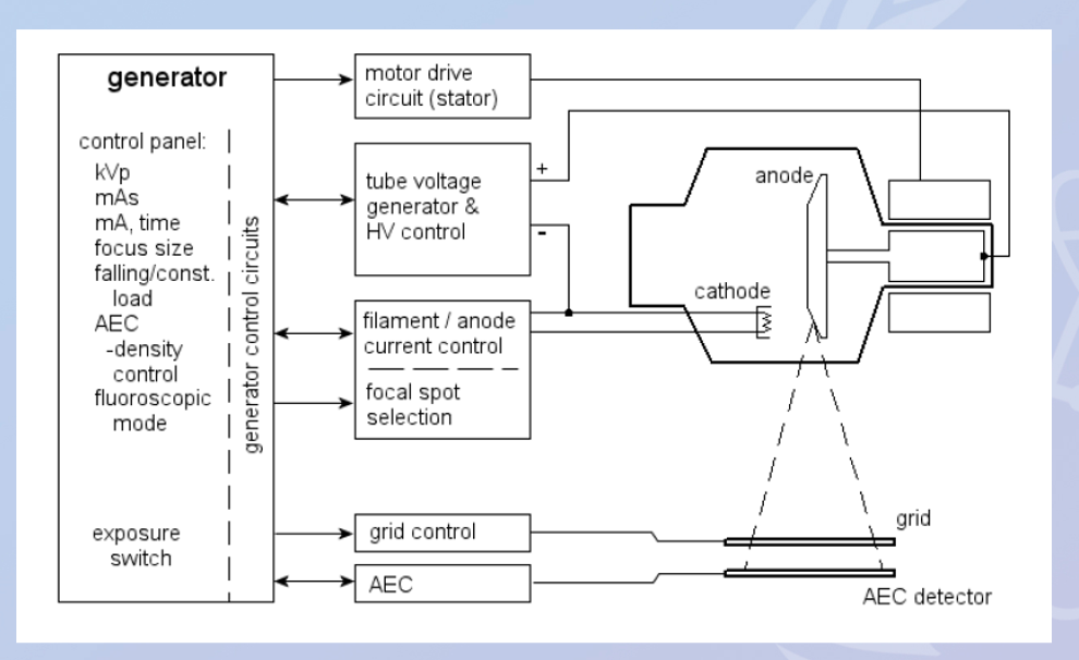
the purpose of the x ray generator is to provide the electrical power required for the operation of:
the x ray tube and circuits controlling exposure timing
the image receptor automatic exposure control acquisition
the key components of the generator are:
filament heating current
high voltage supply
motor drive circuit for stator windings
exposure control for the image receptor dose required
operational control
schematic diagram of an x ray generator and tube
learn how to draw this
generator technologies:
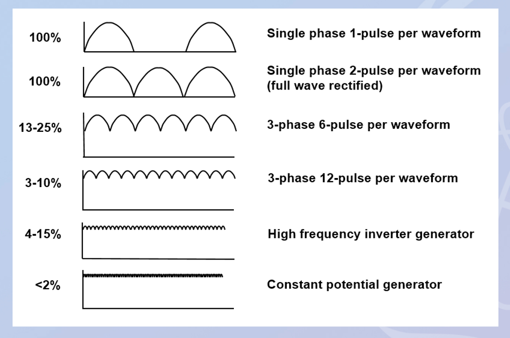
single phase generators (1 and 2 pulse per waveform)
capacitive discharge generators
3-phase generators (6 and 12 pulses per wavelength)
constant potential generators
high frequency inverter generators
what do most modern x ray equipment use?
microprocessor controlled high frequency inverter generators supplied from single or 3-phase mains power
single phase mains power is typically only used for…
lower power equipment such as dental x ray equipment
ripple
ripple is undesirable as it results in the high voltage applied across the tube varying with time and this can have a negative effect on the output spectrum and patient radiation dose
the ideal generator technology would result in no ripple but in practice low levels of ripple can be achieve with modern systems with conditioning circuitry