T8 - Diodes
 Call Kai
 Learn
 Practice Test
 Spaced Repetition
 Match
 Flashcards
 Knowt Play
1/54

There's no tags or description
Looks like no tags are added yet.
55 Terms
Diode
A two terminal electronic device that conducts current in one direction but not the other
Anode
p-type side (excess holes)
Cathode
n-type side (excess electrons)
pn junction
Creates a natural E-field barrier in diode that allows or opposes charge motion
Forward Bias Condition
Anode at higher potential that cathode
Forward Bias Effect
Barrier reduced, large current is allowed for a small forward voltage
Reverse Bias Condition
Anode at lower potential than cathode
Reverse Bias Effect
Barrier increased, only very small reverse current flows
Real volt-ampere characteristic

Forward Bias Region
Almost no current until ~0.6 - 0.7V (knee)
Reverse Bias Region
Very small leakage current ≈ 1nA at room temperature
Breakdown Region
At sufficiently large reverse voltage, current increases sharply
Real (exponential) Model
Diode model with greatest accuracy
Ideal Model
Diode model with fastest ON/OFF decisions
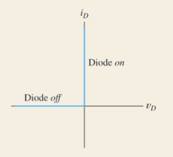
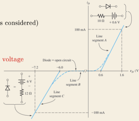
Simple Piecewise-Linear Model (constant drop Vf)
Diode model that is more realistic than ideal but still simple

Piecewise-Linear Model (multi-segment)
Diode model that has better approximation in forward and breakdown regions
Assume, Replace, Solve, Check
Steps of diode analysis
LED
A diode that emits visible light when forward biased
LED Construction
Made from compound semiconductors, material choice sets colour
Electrons recombine with holes
Produces light in an LED (releases energy as photons)
LED Brightness
Determined by forward current (increases with current)
1-3V
LED forward voltage
20mA-100mA
LED current ratings
Current Limiting Resistor
Prevents damage to LED due to excess current flow
Rectifier Diode in Parallel
Prevents LED damage due to reverse voltage
Zener Diode
Designed to operate in breakdown to achieve a constant voltage
Zener Diode Characteristic
Small 𝛥V for large 𝛥I, thus consistent voltage maintained
Zener Diode Conditions
Series resistor required, minimum supply larger than desired output, Zener must be in breakdown
Real Diode Curve Analysis
Uses graphical load-line, accurate and best for simple circuits
Diode Model Analysis
Replace diode w/ simple equivalent circuit, faster analysis
Q Point (Operating point)
Point where load-line intersects diode V-I curve
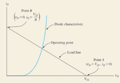
Thevenin Equivalent Circuit
Circuit used for diode load-line analysis

KVL on Thevenin Equivalent Circuit
Method for deriving load-line equation
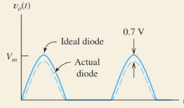
Half-Wave Rectifier
Comprised of a single diode and load RL

Half-Wave Rectifier Output
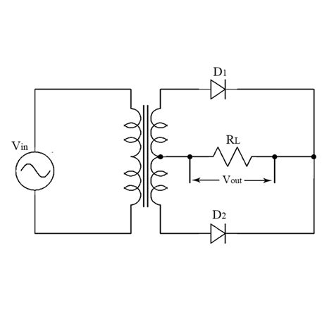
Two Diode Full-Wave Rectifier
Comprised of two diodes and a centre-tapped transformer
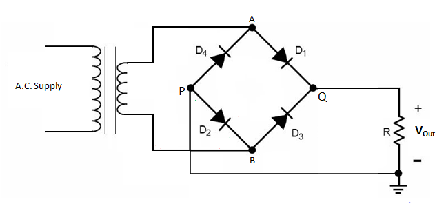
Bridge Full-Wave Rectifier
Comprised of four diodes and an optional transformer
Full-Wave Rectifier Output

Half-Wave Rectifier Function
vL(t) = 0 (OFF), vL(t) = vmsin(ωt) (ON)
Full-Wave Rectifier Function
vL(t) = |vmsin(ωt)|

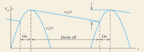
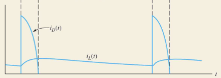
Smoothing Capacitor across RL
Charges near peak when diode ON, discharges through RL when diode OFF
Voltage Waveform w/ Capacitor
Current Waveform w/ Capacitor
Half of half-wave rectifier
Required capacitance for full-wave rectifier
Wave Shaping Circuits
Use diodes to modify an input waveform
Clipper Circuits (Limiters)
Prevents vo from going above/below set levels
Diode OFF
Input within limit of clipper, vo ≈ vin
Diode ON
Input exceeds limit of clipper, output held near limiting level
Practical Clipper
Uses Zener diode(s) to set limiting level

Clamp Circuits
Shifts a waveform up/down by adding a DC component, clamps one extreme of a waveform to chosen level

Transformer, rectifier, filter capacitor, regulator
Typical AC to DC conversion chain
Transformer Role
Sets AC level and isolation
Rectifier Role
Makes pulsating DC output (produces rectified, unidirectional waveform)
Filter Capacitor Role
Reduces ripple (smoother DC)
Regulator Role
Delivers nearly constant DC despite ripple/load changes