50. pelvic ring injury
 Call Kai
 Learn
 Practice Test
 Spaced Repetition
 Match
 Flashcards
 Knowt Play
1/49

There's no tags or description
Looks like no tags are added yet.
50 Terms


Plain radiographs and matching ghost images, respectively, of patient with APC III injury: AP (A, B); inlet (C, D); and outlet (E, F) views.

Zone III = بیشترین ریسک neurological injury (تا 60%).

CT scans of patient with LC II injury.
A, B: Axial and coronal CT scans. C: Three-dimensional (3D) AP. D: 3D inlet. E: 3D outlet. F: The 3D image can be manipulated and rotated to visualize injury (180-degree rotation for posterior view). G: A 3D rotation for lateral image depicting crescent fracture

Patient with spinopelvic disassociation.
A: Axial cut clearly shows bilateral sacral fractures. B: Sagittal reconstruction shows the kyphotic deformity seen with spinopelvic disassociations. C: A 3D CT scan demonstrating spinopelvic disassociation.

Identifying and treating elderly patients with pelvic pain and trauma.

Patient with LC I pelvic ring injury undergoing stress examination under anesthesia.
A: Fluoroscopic inlet view without stress. B:Same view with internal rotation stress applied through the outer aspect of the ilium bilaterally, displaying shortening anteriorly with internal rotation.

Pelvic Ring Injuries: TILE CLASSIFICATION

Pelvic Ring Injuries: YOUNG AND BURGESS CLASSIFICATION[368]

Patient with LC III fracture pattern.
A: Inlet reconstruction demonstrates posterior and anterior pelvic ring injuries on the right side. B, C: Axial CT scan of the cranial and caudal aspect of the posterior pelvic ring. Cranially the sacral ala fracture propagates into the SI joint and exists through the iliac “crescent” fracture. Caudally it appears that the left SI joint might be slightly wide, representing possible injury to left SI joint. D: Schanz pin placed into left hemipelvis and external and internal stress performed through pin, with widening of the left SI joint noted with external rotation.

Patient with APC I injury.
A: AP radiograph showing widened symphysis. B, C: CT scan axial and coronal cuts showing measurement of less than 2.5 cm at symphysis. D–F: 3D reconstructions of AP, inlet, and outlet views. Note the left ramus fracture with external rotation displacement.

Patient with vertical shear injury.
A–C: AP, inlet, and outlet view radiographs showing vertical displacement of right hemipelvis through a complete sacral fracture and transverse process fracture avulsion (arrow). D, E: Axial and coronal CT scans. F, G: 3D CT scan reconstructions of inlet and outlet views.
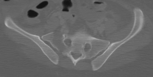
CT scan showing zone I sacral fracture (lateral to the foramen).
CT scan showing zone II sacral fracture—through the foramen—with fragment (arrow) in the S1 foramen resulting in neurologic deficit.


CT scan cuts showing zone III sacral fracture through the S1 body (A) and lateral to foramen with extension into spinal canal (B).
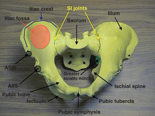
Bony model of pelvis with indicated landmarks.
ASIS, anterosuperior iliac spine; AIIS, anteroinferior iliac spine; SI, sacroiliac.

Schematic drawing showing ligamentous structures of the pelvis with the left transparent hemipelvis.
A: Anterior view—ligaments intact on right side, with the sacrospinous and ILL (lumbosacral band) removed on left side for better visualization of underlying structures (sacrotuberous, lateral coccygeal, and full visualization of anterior sacroiliac ligaments). B: Posterior view—ligaments intact on right side, with the long posterior sacroiliac and sacrotuberous ligaments removed on left side for better visualization of underlying structures (sacrospinous, interosseous sacroiliac, and short posterior sacroiliac ligaments).

Schematic drawing showing the neurovascular structures within the pelvis.
The left hemipelvis is visualized with a transparent sacrum and L5 body. The internal iliac branches are seen anterior to the SI joint. The proximity of the bladder and urethra to the symphysis is appreciated. The nerve roots exiting the foramen are demonstrated with the L5 nerve root anterior on the sacral ala.

Schematic drawing showing vascular structures intimate with ligamentous structures of the pelvis.

A 56-year-old patient after a motor vehicle accident with a binder placed in the field.
The patient was hemodynamically stable and the binder was subsequently removed. A: AP radiograph with binder showing well-reduced pelvis. A sacral fracture is noted on the right but there is no apparent anterior widening. B: Anterior injury revealed

67-year-old very active woman crushed by a falling tree had a comminuted bilateral anterior ring injury with a displaced sacral fracture with excellent posterior fracture reduction reads.
A: Initial AP pelvis radiograph taken out outside hospital. B, C: Outlet and inlet reconstructions from CT of pelvis. D, E:Axial slices of sacral fracture with anterior sacral comminution and posterior displacement with no comminution on posterior aspect of sacrum. F, G: Bilateral parasymphyseal rami fractures. H, I:Intraoperative fluoroscopic images during prone midline posterior approach. Note reduction obtained with large spin-down Weber clamp with the appropriate vector to correct subtle cranial displacement and widening. Medial tine placed on spinous process and the other tine placed on PSIS. J, K: Postoperative CT scan reconstructions, showing final construct. Note additional fixation was obtained utilizing lumbopelvic fixation which was done after sacral fracture reduction and transsacral screw placement. The patient was then placed supine and anterior external fixator was applied for 5 weeks. L, M: Postoperative CT scan, axial cuts through sacrum.
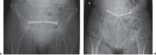
An 86-year-old woman with a minimally displaced sacral U-type fracture with inability to ambulate due to worsening pain after a low-energy fall 6 weeks prior.

Placement of an AIIS external fixator.
A: Obturator outlet view is obtained with a bent 2-mm K-wire overlying the skin to approximate start site. B: Iliac oblique view demonstrating the cranial position of the K-wire in relation to the AIIS. C: Cannulated 4.5-mm drill and protective sleeve are placed over the K-wire and directed between the inner and outer table on the obturator inlet view. Drill advanced roughly 2.5 to 3 cm from start site. D: Drill removed after appropriate trajectory obtained on iliac oblique and obturator inlet and sleeve left in place and 5-mm Schanz pin is advanced just cranial into the sciatic buttress cortex. E: With the relative cranial to caudal direction of the Schanz pin the patient is able to sit up.

59-year-old morbidly obese man (BMI 52) with APC pelvic ring injury who was referred after operative management.
A, B: AP and inlet imaging demonstrating hardware failure and pubic symphysis widening. C: Anterior hardware removed, and symphysis reduced using Jungbluth with placement of a 10-hole curved recon plate (different hole spacing then precontoured previous plate) on the superior aspect of the rami. D: Additional 2.7-mm strength (thick) locking plate, placed anteriorly with locking screws. E, F:Long-term follow-up films demonstrating no loss of reduction or hardware failure

ORIF of Symphysis Pubis: SURGICAL PITFALLS AND PREVENTIONS

The corona mortis is demonstrated on the inside of the superior pubic rami about 6 cm from the symphysis.
It represents the anastomosis of the obturator artery and the external iliac artery

Patient with a pubic symphysis disruption and a superior rami fracture that was spanned.
A: Preoperative AP radiograph. B:Postoperative inlet radiograph, note the placement of the two most lateral screws in the plate being out of the hip joint. C:Alternative technique for fixation in the setting of a rami fracture and a pubic symphysis disruption. This patient had bilateral superior rami fractures and a pubic symphysis disruption. Patient underwent bilateral antegrade anterior column screw placement and pubic symphysis ORIF.
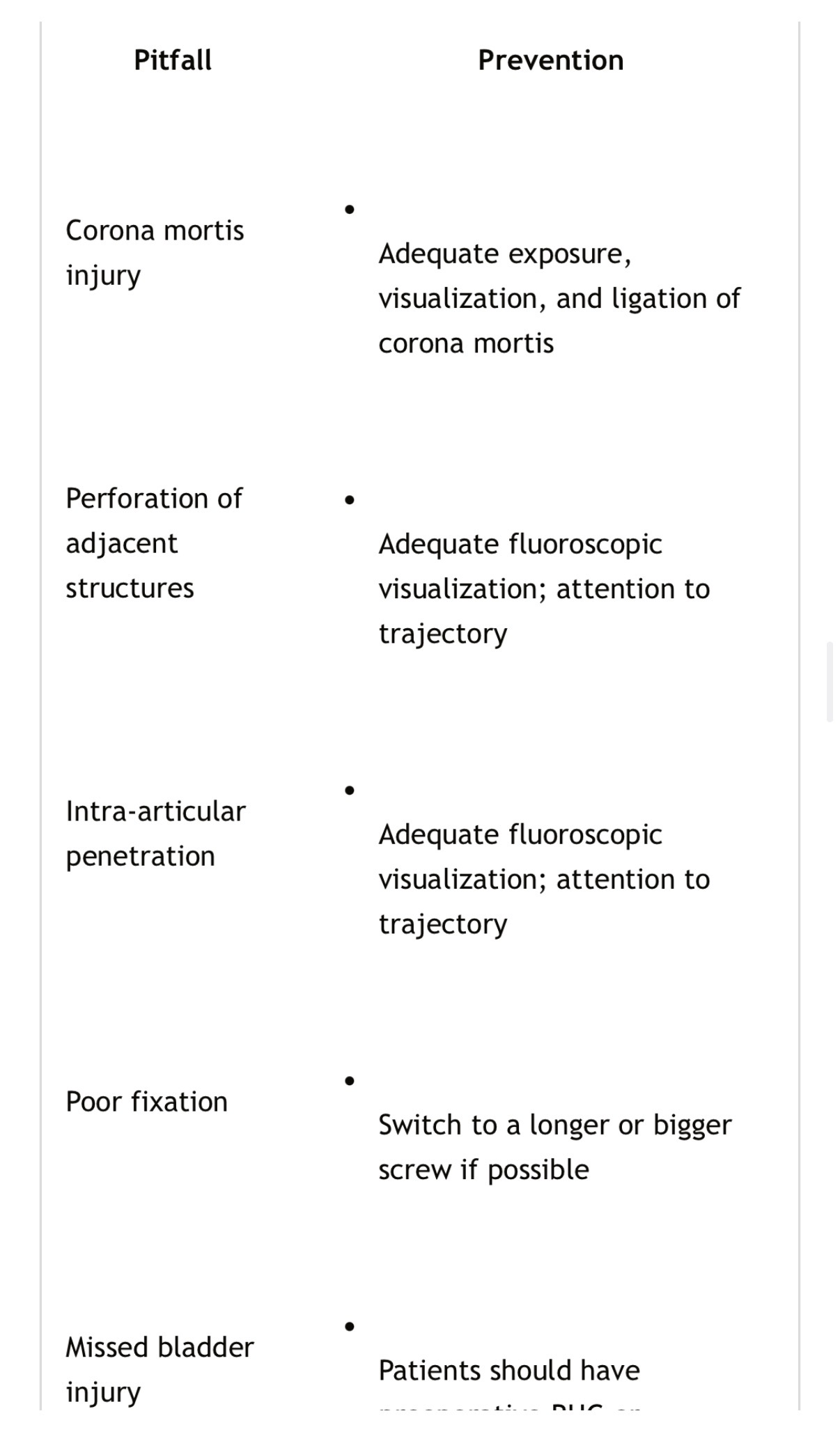
Stabilization of Ramus Fractures: SURGICAL PITFALLS AND PREVENTIONS

Sacral fracture kyphosis correction with prone positioning.
A: Sagittal CT scan with the patient in the supine position, note significant kyphosis. B:Lateral fluoroscopic view of the sacrum with the patient in the prone position. Note the significant correction of kyphosis that occurred with prone positioning
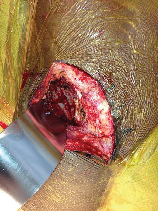
Deep exposure of posterior approach showing elevation of gluteal musculature off lateral aspect of ilium and exposure of iliac wing fracture.

Supine patient positioning for anteriorly based approach to SI joint.
Note bumps placed under knee to relax the iliopsoas during the lateral window approach.

Approach to SI joint from the anterior.
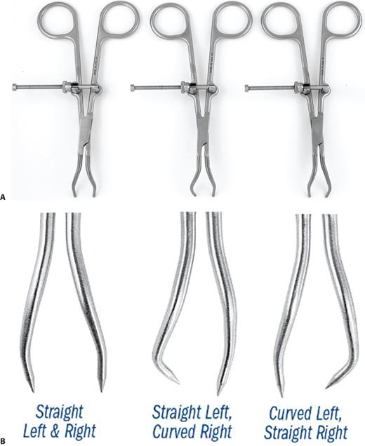
Modified pointed reduction clamps.
A: Small version with straight-straight tines, straight-left curved-right, and curved-left straight-right tines. B: Closeup of the different tines in the medium version of the modified Weber clamps.

48-year-old man with pubic symphysis disruption and complete ilium fracture after motor vehicle collision.

ORIF of Iliac Wing Fractures: SURGICAL PITFALLS AND PREVENTIONS

Fixation of Crescent Fractures: SURGICAL PITFALLS AND PREVENTIONS

Fluoroscopic inlet images of the pelvis of the patient shown in Figure 50-64.
For an optimized inlet view, the anterior cortex of the S1 body should be overlapping the anterior cortex of the cranial anterior aspect of the S2 body. Note the progression of overlap between the anterior cortex of S1 and the cranial anterior aspect of S2, progressing from 0 degrees to 5 degrees to 12 degrees.
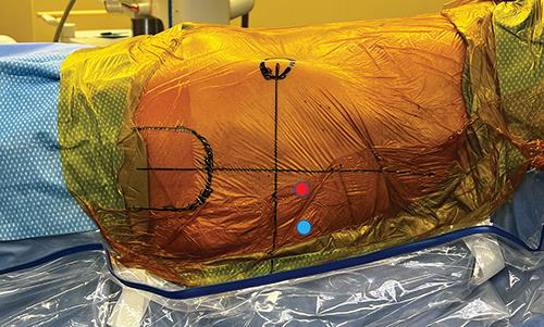
Skin insertion points for IS-style screws (blue circle) and sacral-style screws (red circle).
Both are in the posterior caudal quadrant of a line drawn down from ASIS and line drawn along in line with the femoral shaft

Iliosacral Screw Fixation for Sacroiliac Joint Dislocation: SURGICAL PITFALLS AND PREVENTIONS

Farabeuf clamp picture.
Note clamp is placed over screws and screw position determines reduction vector. Gray lines represent 5-mm Shantz pin placement into iliac crest along gluteus medius pillar and AIIS. They Schanz pins can be used as joysticks when attached to T-handles

Jungbluth clamp can be used to reduce multiplanar deformity across the SI joint.
A: First cranial/caudal direction can be corrected by levering on one side of the clamp. In the figure. if the clamp is levered on the right side (toward the contralateral SI joint, with pressure onto the right sacral ala), then the left ilium and hemipelvis will be moved cranially. B: Anterior/posterior reduction is then made by rotating the clamp. In this image, clockwise rotation will result in anterior translation of the left hemipelvis. C: Last, the joint can be compressed by squeezing the two handles of the clamp.
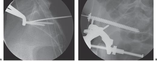

Goose clamp placed across SI joint.
One footprint is placed on the sacral ala and other footprint placed on the outer aspect of ilium.

Picture demonstrating location of plate spanning SI joint.
Black line represents course of L5 nerve root. Placing two holes medial to the SI joint places the L5 nerve root at risk. Also placing the plate on the most anterior aspect of the joint places the L5 nerve root at risk. Ideally, hole number 2 is centered over the SI joint and posterior to the sacral promontory
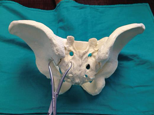
Model demonstrating reduction of the SI joint with a pointed reduction forceps from the posterior approach using inferior clamp placement.

Percutaneous Iliosacral Screw Fixation of Sacral Fractures: SURGICAL PITFALLS AND PREVENTIONS


A 67-year-old anorexic woman had 2 weeks of posteriorly based pain after slipping on wet concrete.
A: Initial axial cuts at 2 weeks. B: Sagittal CT cut at 2 weeks. C: MRI obtained at 4 weeks because the patient continued to have pain. Sagittal MRI demonstrated increased edema at the S2 level. Physician continued nonoperative management. D: At 5 weeks, patient had increased difficulty ambulating secondary to pain. A repeat CT scan was obtained which demonstrated partial collapse and kyphosis. E: Axial CT scan demonstrating significant decrease in safe zones compared to initial CT scan (in B). This make percutaneous management more challenging and potentially not possible, if the safe zones for placement of screws are no longer available.

Lumbopelvic Fixation for Spinopelvic Disassociation: SURGICAL PITFALLS AND PREVENTIONS

Author’s preferred treatment for anterior pelvic ring injury.

Author’s preferred treatment for posterior pelvic ring injury.