MATS 2001 Exam 1
 Call Kai
 Learn
Learn Practice Test
 Spaced Repetition
 Match
Match Flashcards
 Knowt Play
1/29

There's no tags or description
Looks like no tags are added yet.
Name | Mastery | Learn | Test | Matching | Spaced | Call with Kai | Chat |
|---|
No analytics yet
Send a link to your students to track their progress
30 Terms
metals
repeating crystalline structure
metallic bonds (sea of electrons)
strong and ductile
conductors
ceramics
mix of metal and non-metal; ionic and covalent bonds
regularly arranged atoms (except glasses, which are non-crystalline solids)
strong but brittle, high melting point
high % ionicity → insulators, low % ionicity
polymers
composed primarily of carbon and hydrogen
semicrystalline or amorphous
low melting temp
mostly poor conductors
covalent and van der Waals forces

Energy Well Diagram
deeper curve indicates stronger bonds and therefore higher melting temperatures
also means higher stiffness (E) and lower thermal expansion coefficient
melting temperature
adding thermal heat increases vibration in atoms (which is what temperature measures)
at the melting temperature, bonds break
ionic bonds
“giving” electrons
strongest
≥ 1.6 electronegativity difference is ionic
covalent bonds
“sharing” electrons
similar electronegativities (or same)
electronegativity difference between 1.0 and 1.6 means covalent with ionic tendencies
metallic bonds
sharing loosely held electrons
high electron mobility → conductive
crystal lattice terms
unit cell: smallest repeat entity
lattice parameter (a): unit cell dimensions
coordination number (CN): number of nearest neighbors
atomic packing factor (APF): % volume filled by atoms
isotropy
uniformity in each direction
from anisotropic to isotropic: single crystals, polycrystals, amorphous
stiffness
resistance to any deformation
strength
force or stress a system can withstand before failing
how difficult it is to move dislocations
ductility
distance a material can stretch before failing
toughness
energy a material can absorb before failing
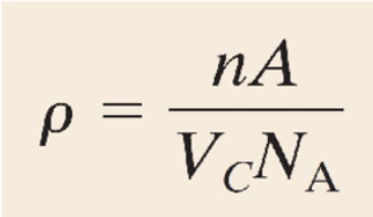
Theoretical Density
complete atomic weight in unit cell / volume of unit cell
n = number of atoms
A = atomic weight
Vc = volume of unit cell
NA = Avogadro’s number
cleaving
occurs ALONG high density planes
common in anisotropic single crystals
isotropic materials typically fracture → random cracks and breakage
diffraction
occurs when a wave encounters regularly spaced obstacles
constructive (double amplitude) and destructive (zero amplitude) interference
0 Dimension defects
point defects
intrinsic → vacancies
extrinsic → impurities, alloys
1 Dimensional defects
line defects
edge
screw
mixed (most common)
2 Dimensional defects
planar defects
grain boundaries
phase boundaries (in multi-phase materials)
twin boundaries
stacking faults (in close packed planes - FCC)
3 Dimensional defects
bulk/volume defects
pores
cracks
foreign inclusions
solubility between metals
atomic size factor
crystal structure
electronegativity
valences
surface hardening
machine softer metal, then harden surface
interstitial diffusion
carburizing
steady state diffusion
flux (J) does not change over time; concentration profile remains constant
non-steady state diffusion
flux J and concentration gradient change with time
enrichment
carburizing
depletion
strain
how much you deform a material
strain hardening
elastic recovery after plastic deformation
dislocations have formed and remain
less ductile from now on, due to lattice strain fields
existing dislocations impede further dislocations
strengthening metals
inhibit dislocation motion (increase the force needed to move one), in other words: make crystal less perfect
grain boundaries
impurity atoms
other dislocations