Auxies Final 2
 Call Kai
 Learn
Learn Practice Test
 Spaced Repetition
 Match
Match Flashcards
 Knowt Play
1/80

There's no tags or description
Looks like no tags are added yet.
Name | Mastery | Learn | Test | Matching | Spaced | Call with Kai | Chat |
|---|
No analytics yet
Send a link to your students to track their progress
81 Terms
The major difference between the discharge and suction valves installed in most low-pressure reciprocating air compressors is that____
a. one valve seats upwards, while the other seats downwards
3 multiple choice options
The unloading system on an air compressor will?
allow for the motor to turn the compressor opposed only by friction
The delivery rate of an axial piston hydraulic pump is controlled by varying the position of the ____
tilting box
A casing drain is provided for axial piston and bent axis variable stroke pumps to___
prevent damage due to agitation and overheating of oil accumulated in the casing as a result of normal internal leakage
A centrifugal pump must have a stuffing box liquid sealing line and seal cages installed if the pump
suction lift exceeds 10 inches Hg vacuum
primary function of J MO-0110
remove air and non-condensable gasses
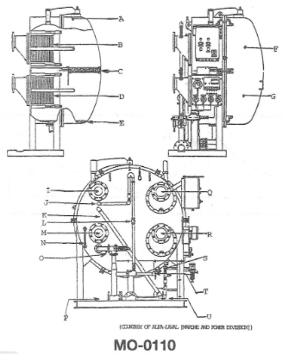
J is attached to what? MO-0110
attached to the air ejector
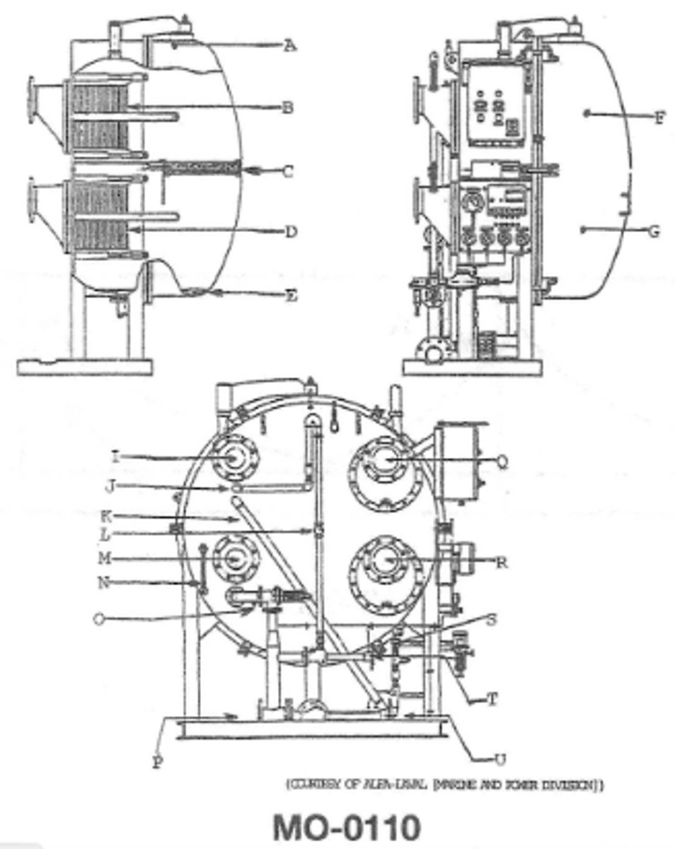
function of DMO-0110
it heats the entering feed water
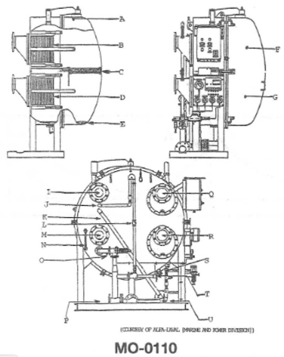
If the demister used in the device shown in the illustration is improperly installed which of the following will occur?MO-0110
there will be an increase in chlorides measured at the distillate pump salinity cell
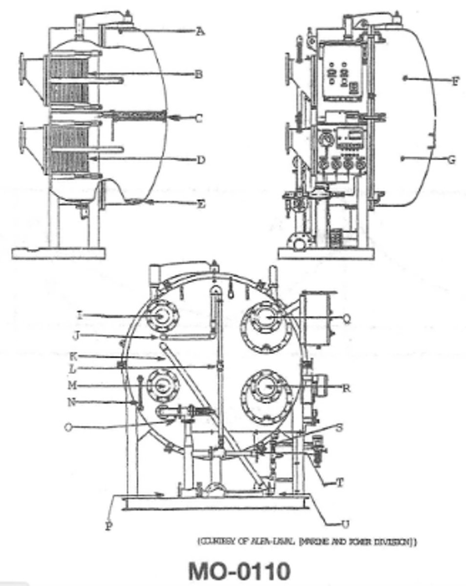
MO-0110 what occurs in G?
the feed water enters the device and vaporizes under vacuum conditions
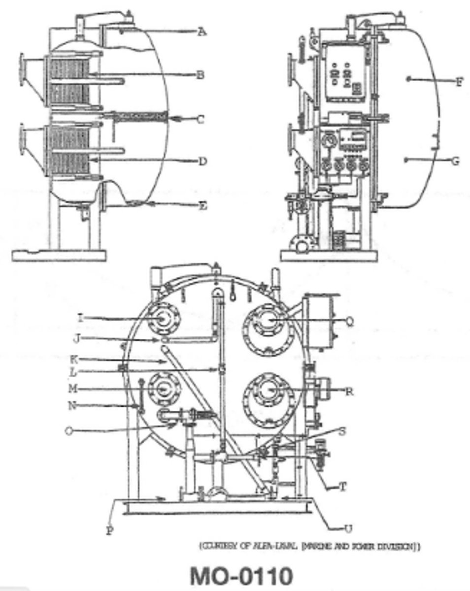
what fluid flow would be expected at connection I MO-0110
the sea water used for condensing the water vapor
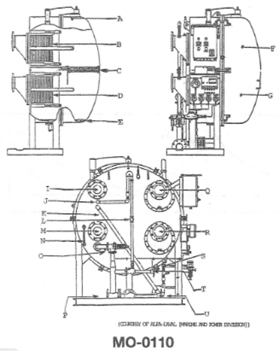
which of the following is NOT a function of the water supply through item PMO-0110
it dosen't supply the operating medium used in the removal of the distillate
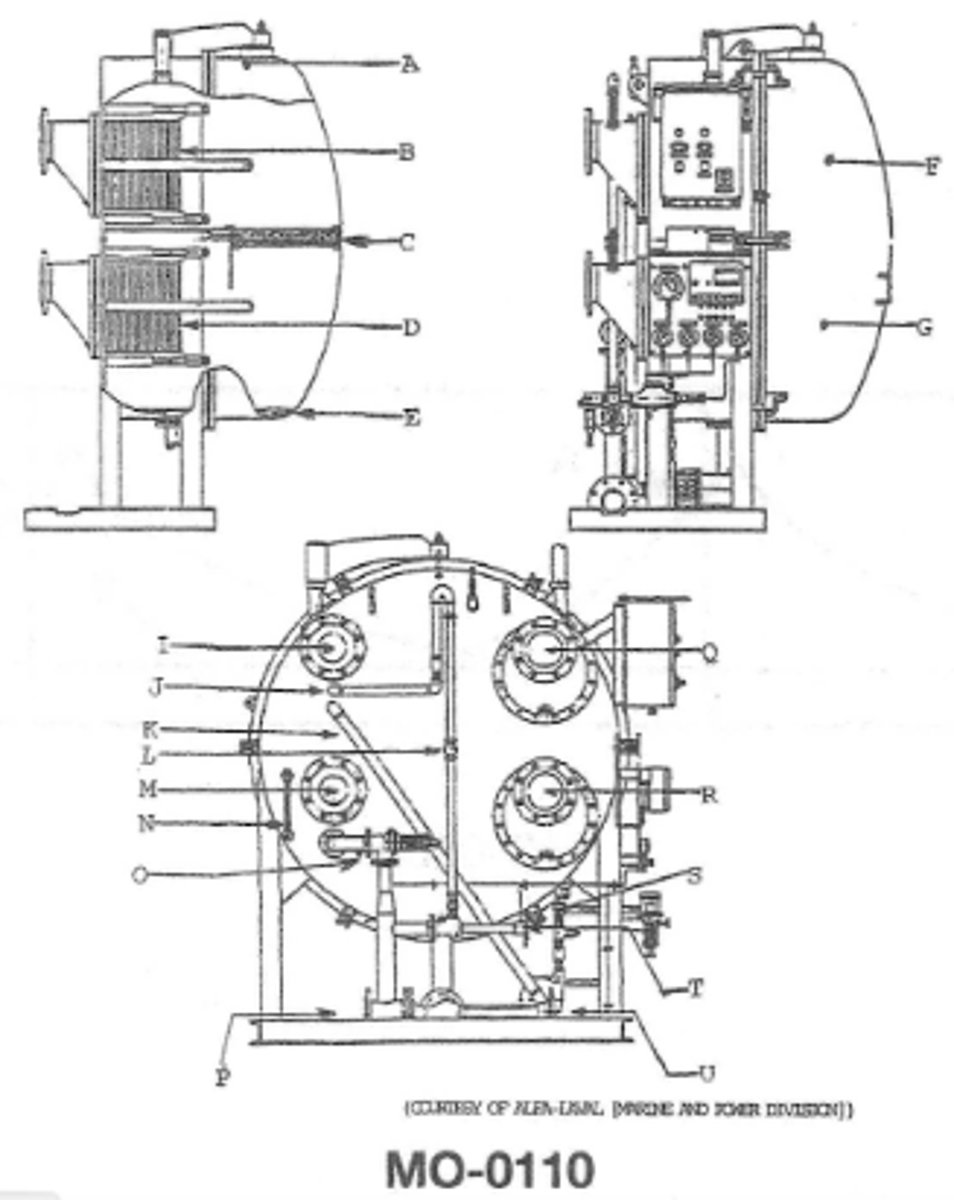
M is the MO-0110
jacket water inlet
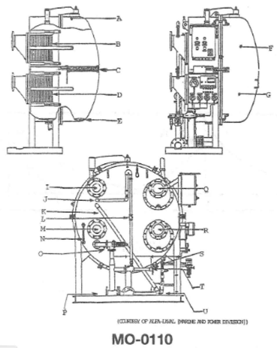
Function of O?MO-0110
control the amount of feed water entering the evaporator
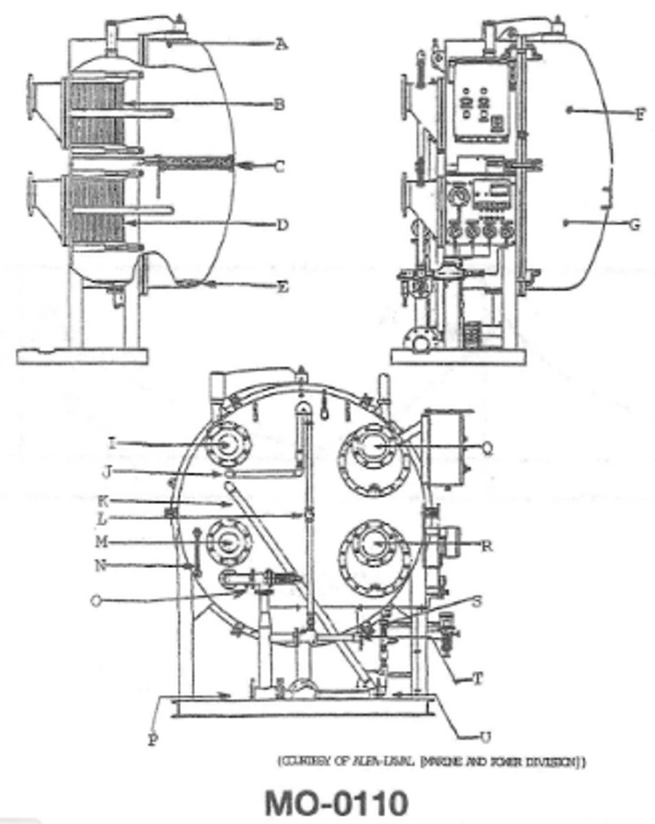
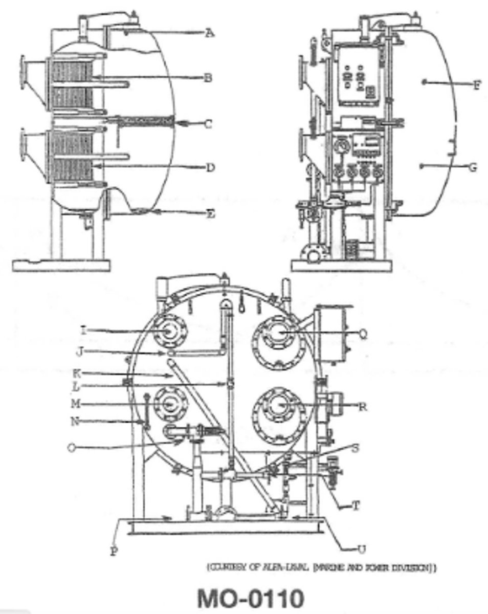
When tightening the plate type heat exchangers show in the illustration care must be taken to MO-0110
use a specific opposing pattern while measuring the distance to which the plates have been compressed
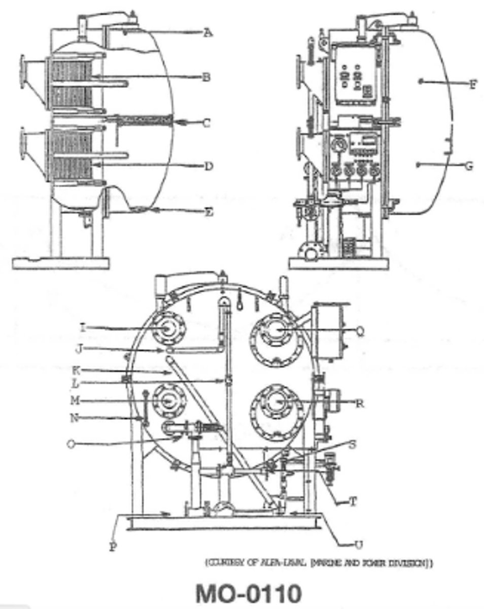
Function of D MO-0110
heats the entering feed water
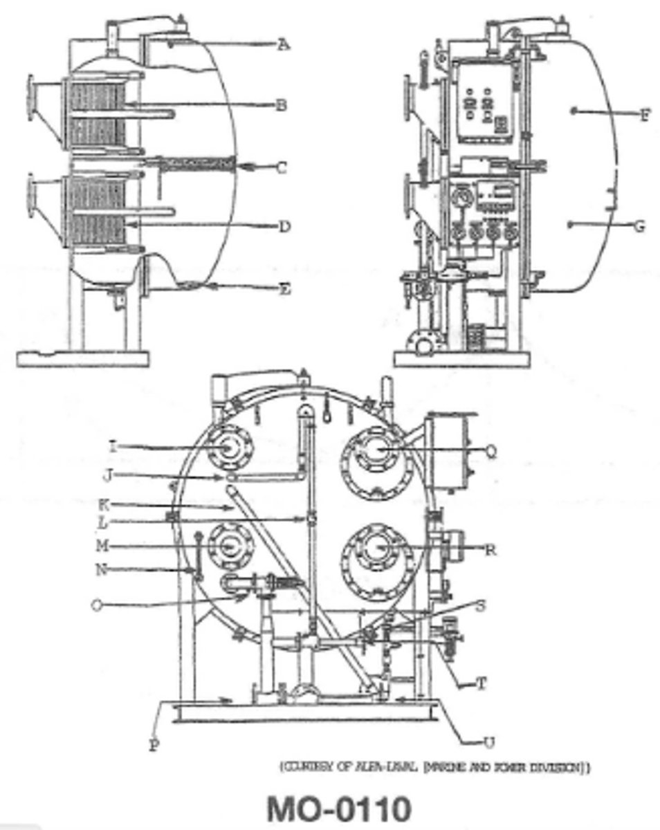
In an actual installaion which of the flanges are connected to the engine jacket water system for the water maker shown? MO-0110
R and M
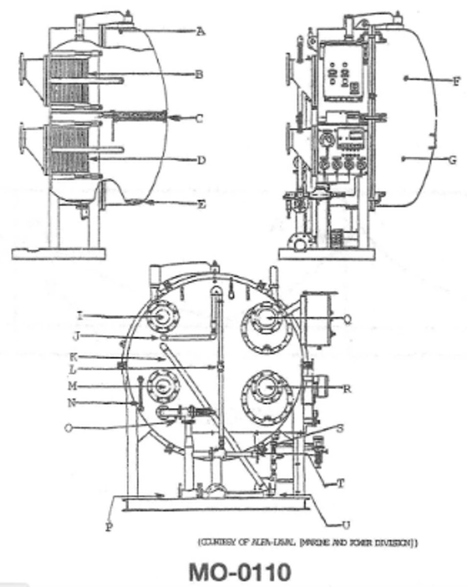
Function of B MO-0110
It condenses the vapors formed in "G"
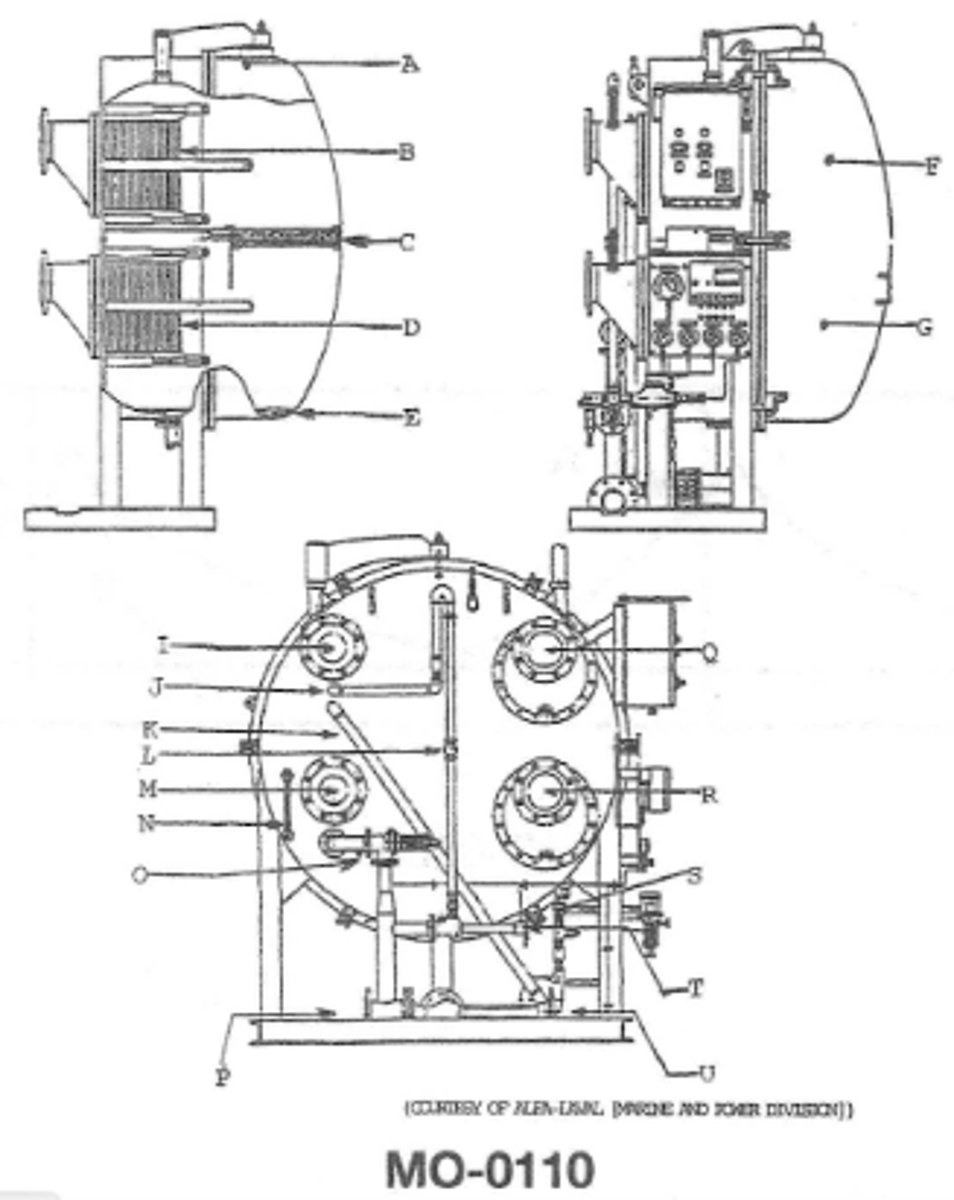
Function of A MO-0110
it serves as a hindge for ease of opening the shell
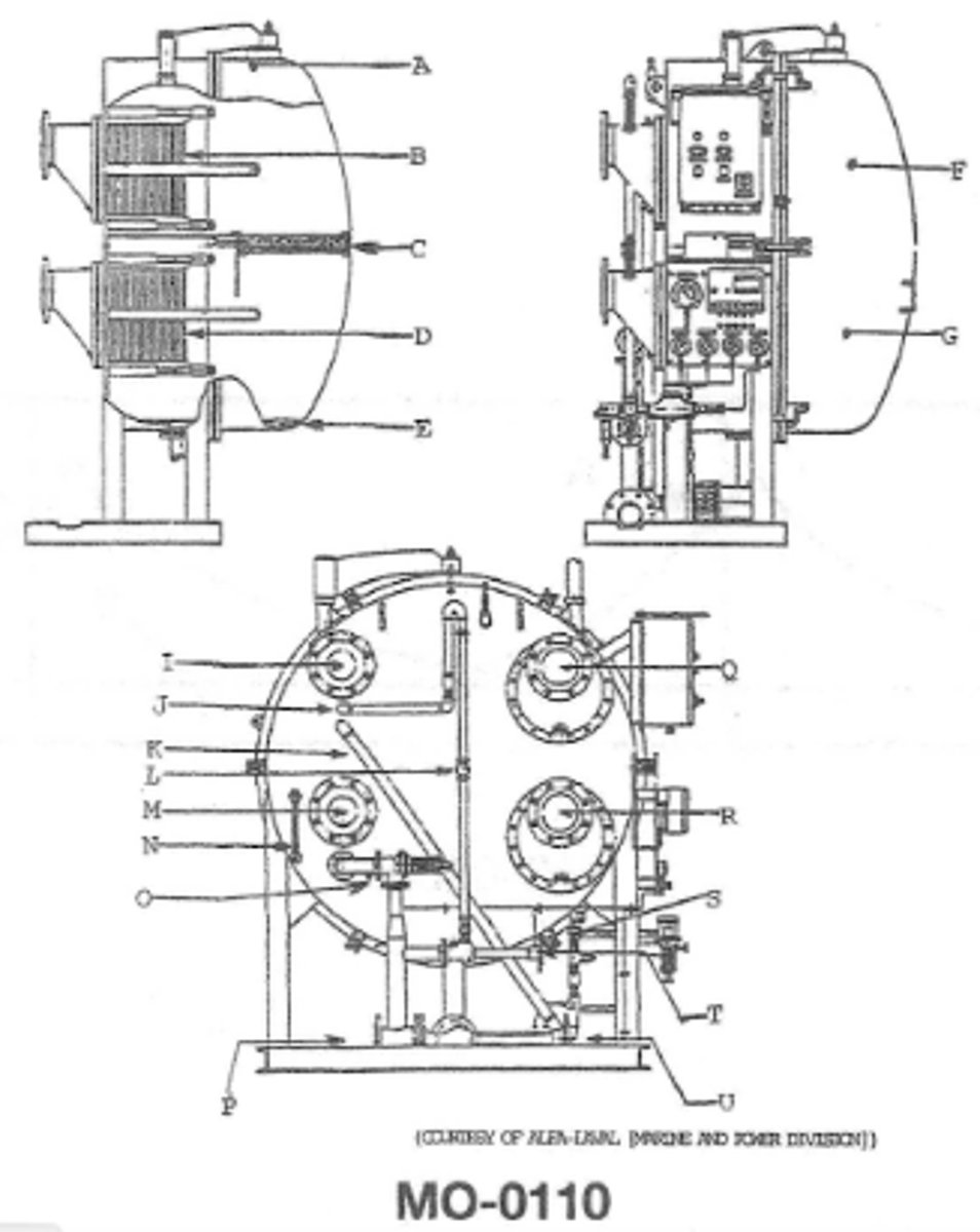
Failure to establish sufficient vacuum when starting up the unit shown in the illustration may be the result of? MO-0110
neglecting to close the vent shell
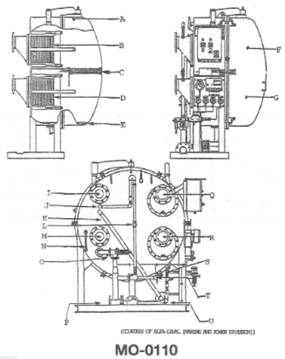
Function of J MO-0110
remove air and non-condensable gases from unit
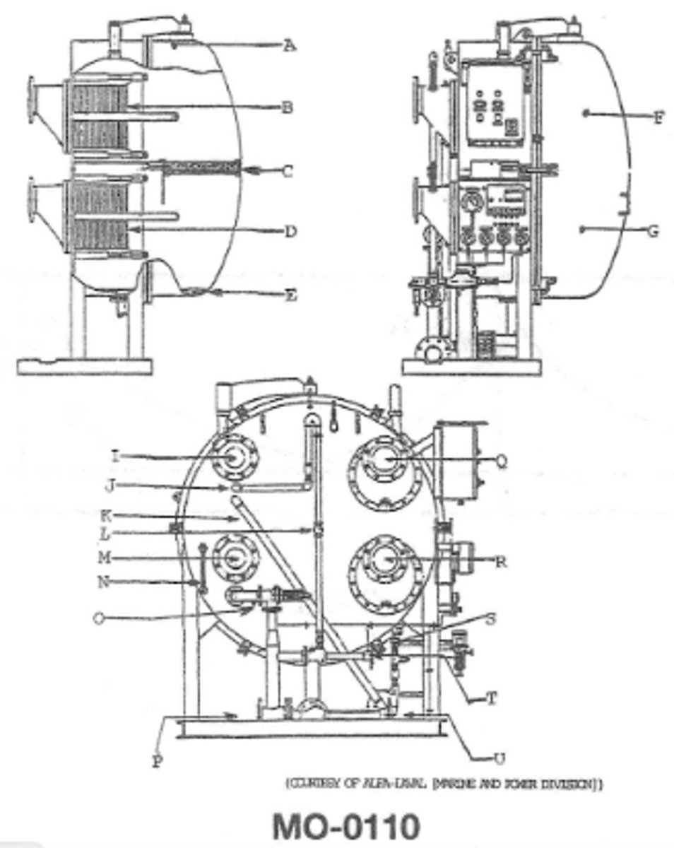
What is the motivation power fluid used in conjunction with the ejector pumps on evaporators? MO-0110
the motive power is the feed water supply
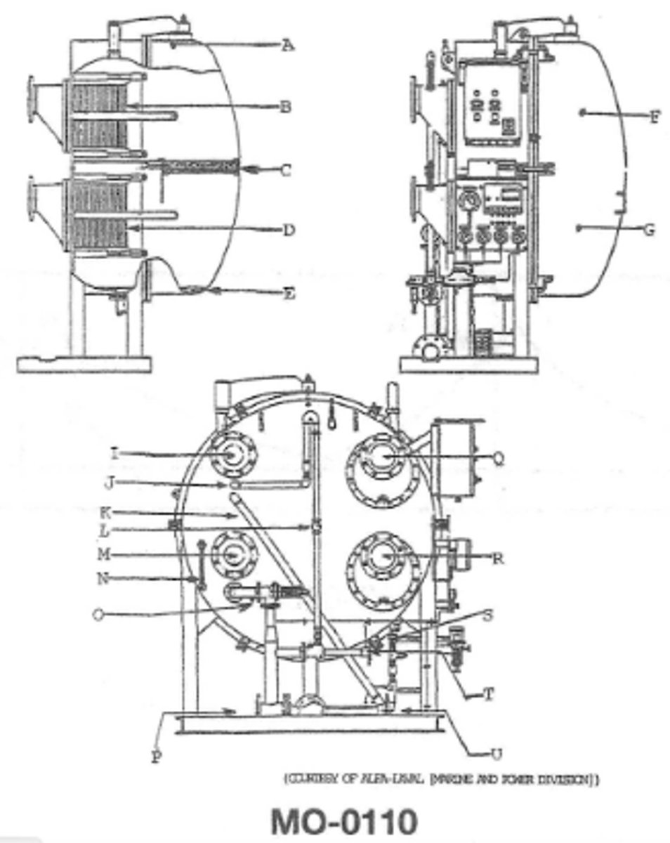
In an actual installation the flange identified by the letter U shown in the illustration can be directly connected from the brine ejector discharge to the MO-0110
saltwater inlet at I
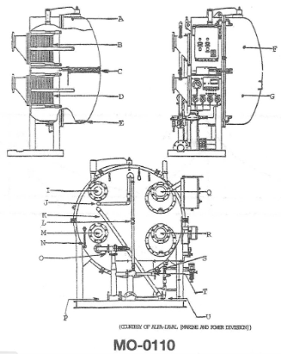
Function of O MO-0110
control the amount of feedwater entering the evaporator
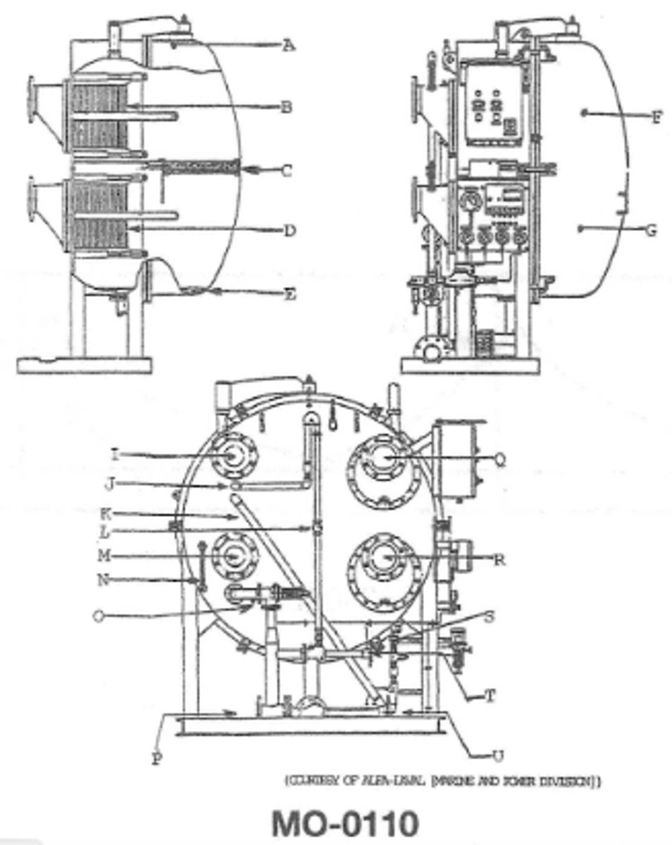
what are the plates made out of MO -0110
titanium
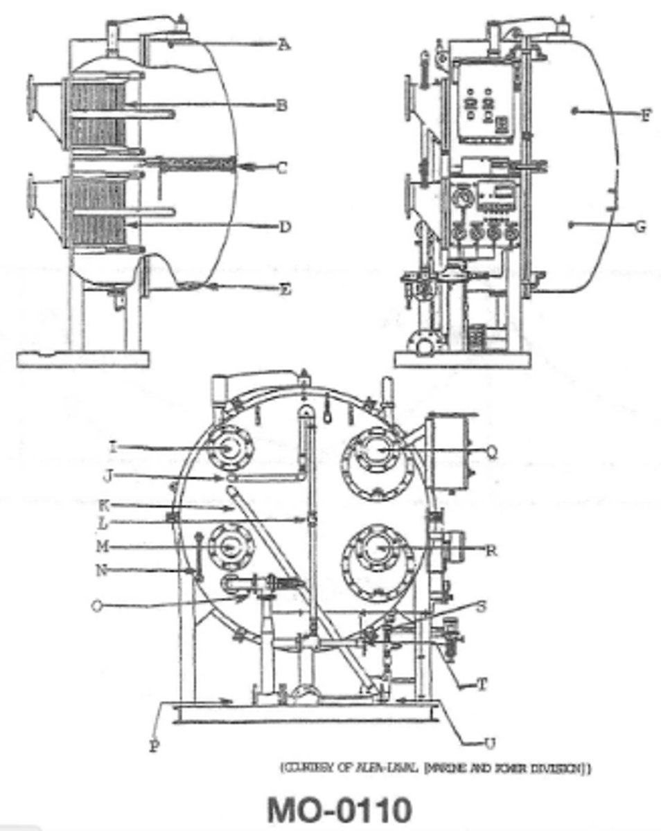
what would cause high salinity of the distillate due to sea water leakage in the illustrated device? MO-0110
failure to properly tighten the bolts of the condenser heat exchanger
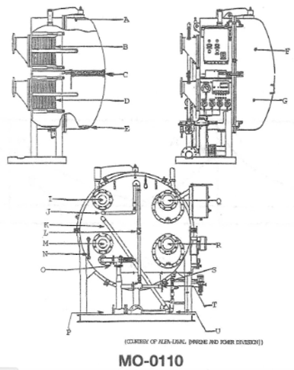
what is s MO-0110
distillate pump discharge
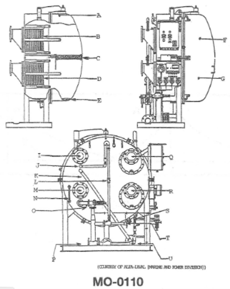
what occurs in F? MO-0110
the vapors produced in section G are condensed and the non-condensable gases are removed
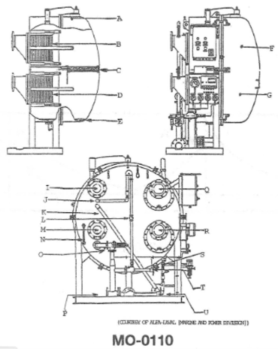
what occurs in G MO-0110
the feed water enters the device and vaporizes under vacuum conditions
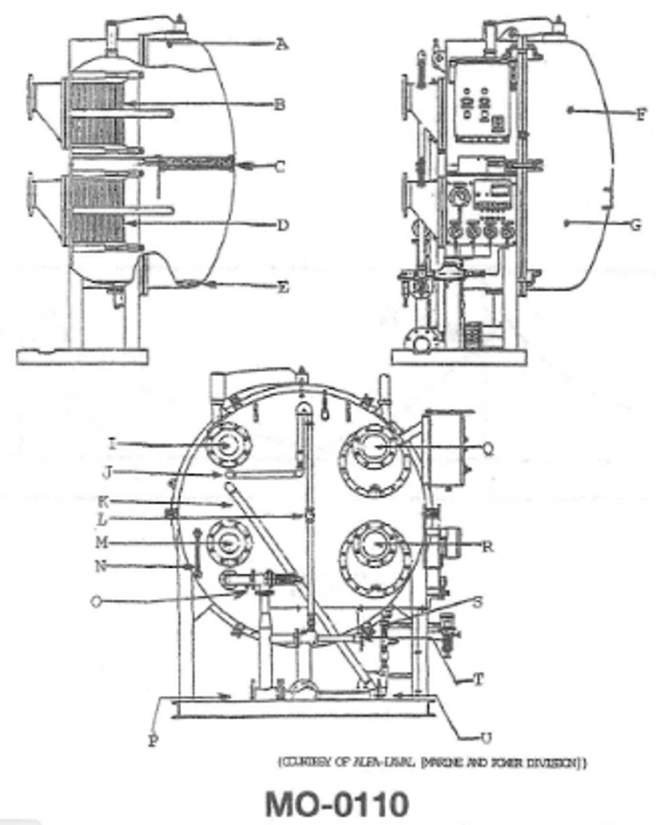
function of B MO-0110
it condenses the vapors form in section G
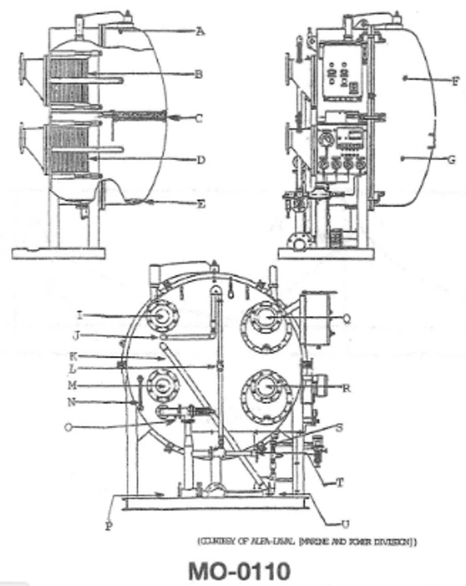
what fluids exits the device at flange R MO-0110
Engine Jacket water
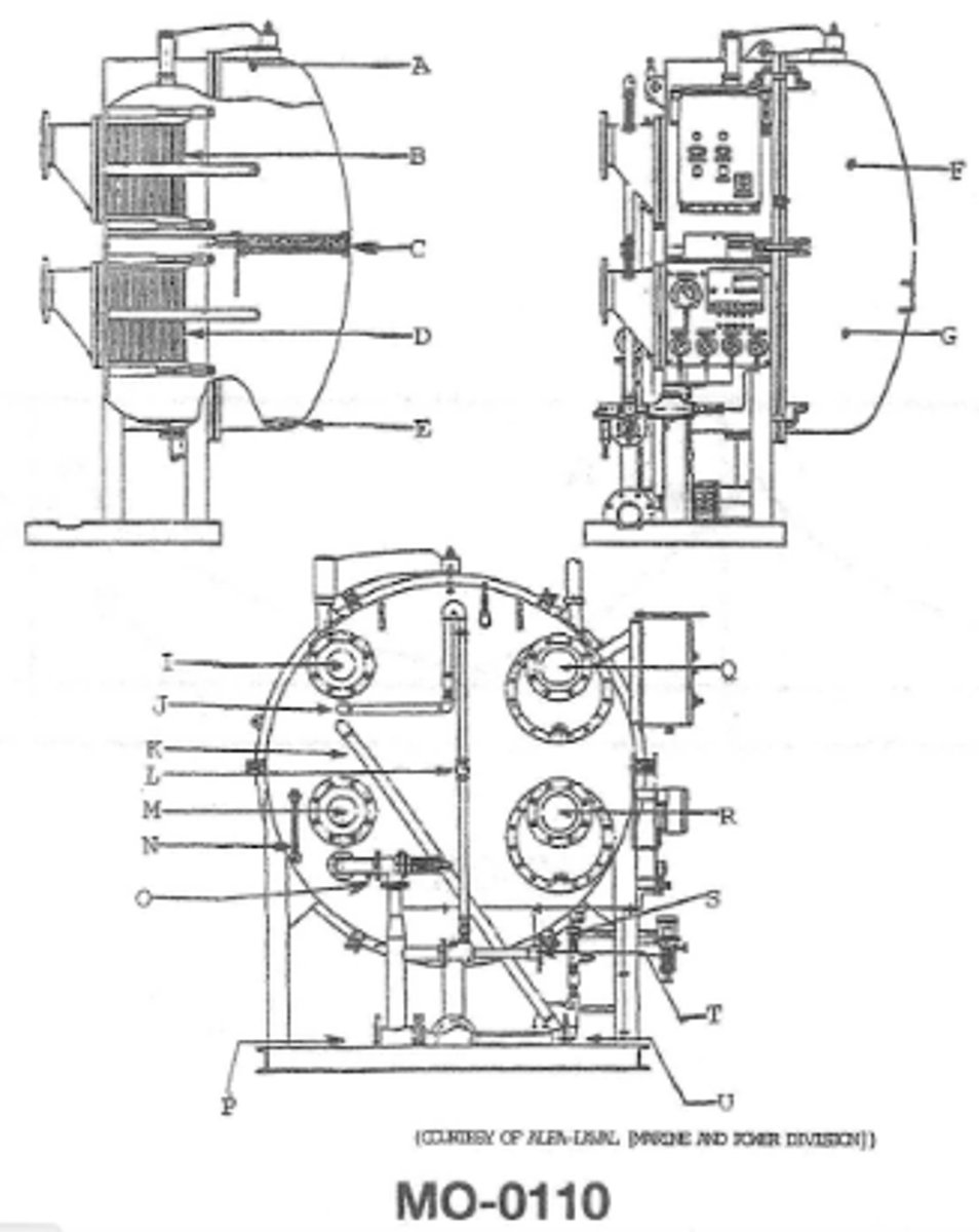
function of C MO-0110
removes moisture entrained in the vapors produced in section G
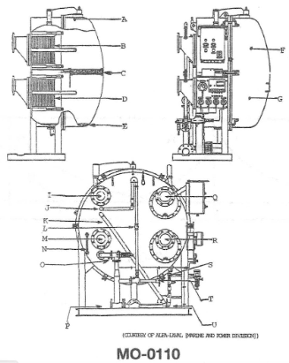
In an actual installation the flange identified by the letter U shown in the illustration can be directly connected from the brine ejector discharge to the MO-0110
overboard discharge line
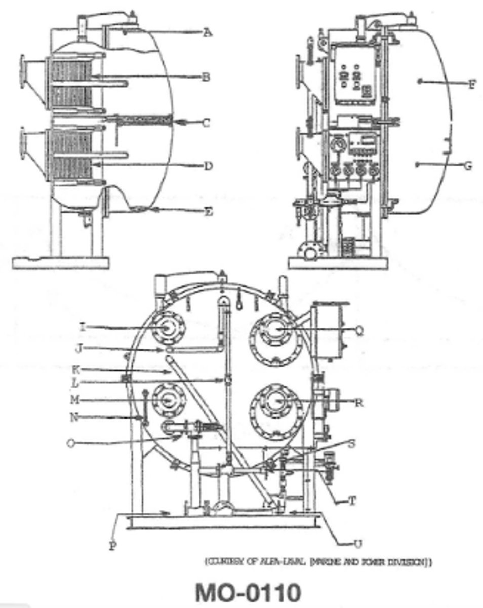
which of the tools listed must be used when retightening the plate type heat exchangers used in the illustration MO-0110
steel ruler or tape measure
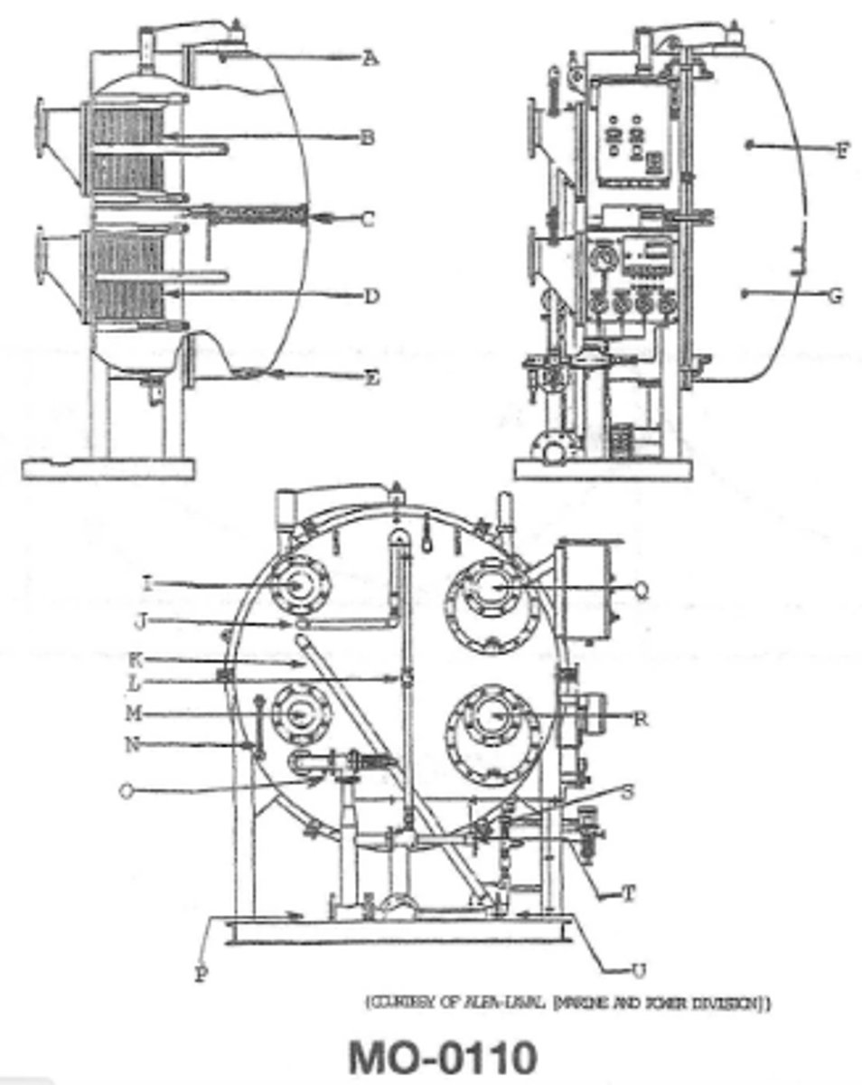
In an actual installation which of the flanges are connected to the condenser section of the water maker? MO-0110
I and Q
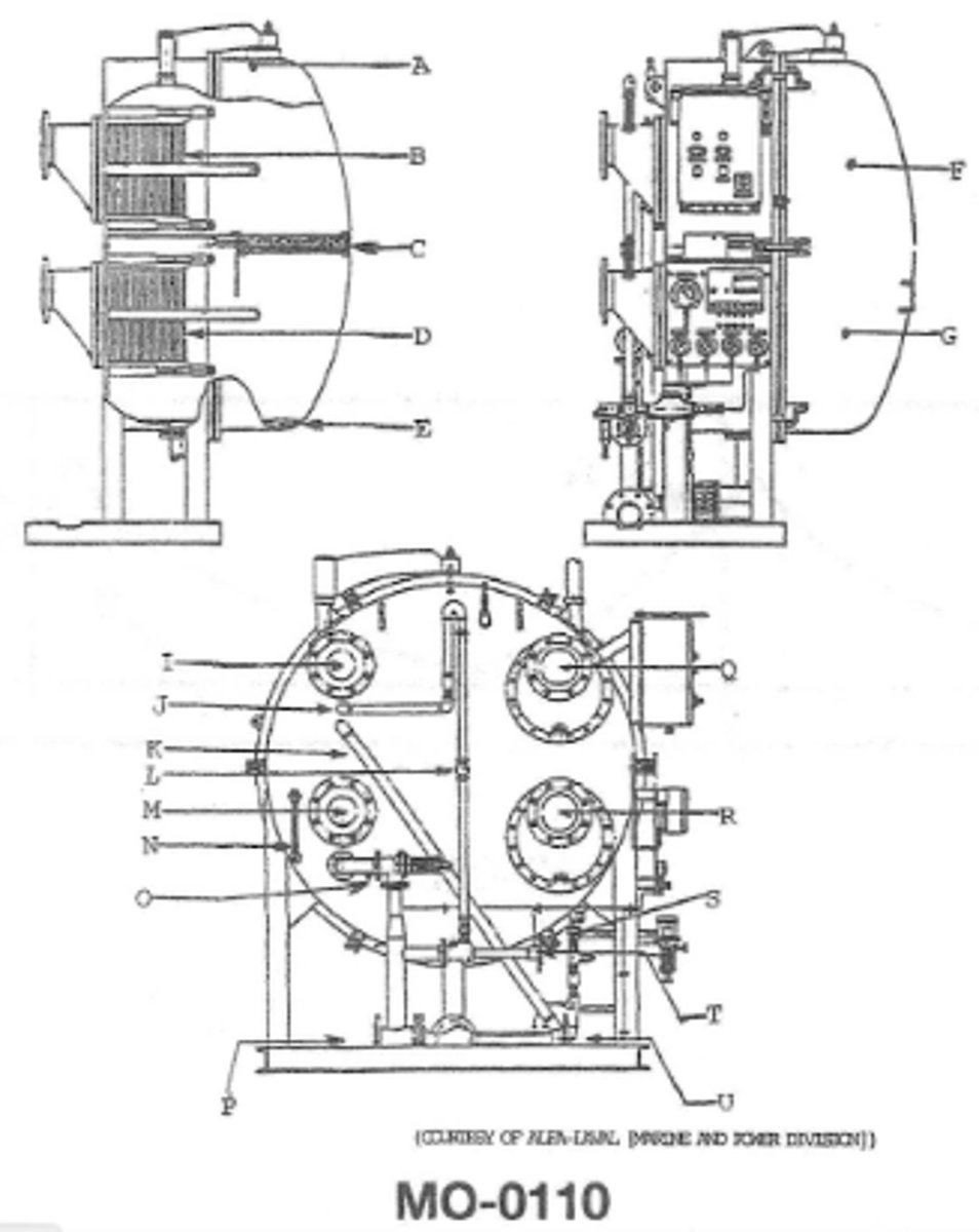
Which of the fluids exits the flange labeled Q MO-0110
sea water from the condenser plate assembly
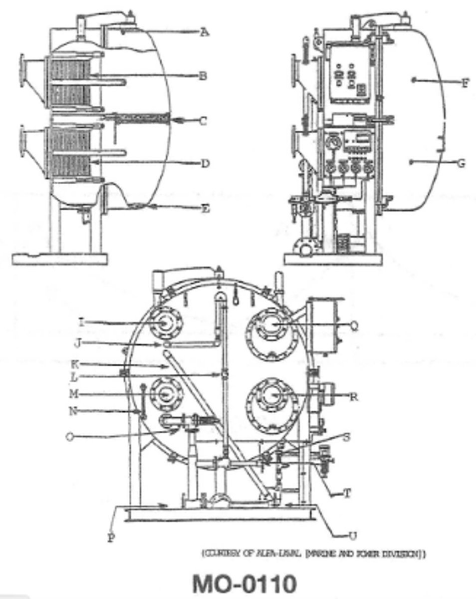
the pipe identified by the letter J shown in the illustration is MO-0110
attached to the air ejector
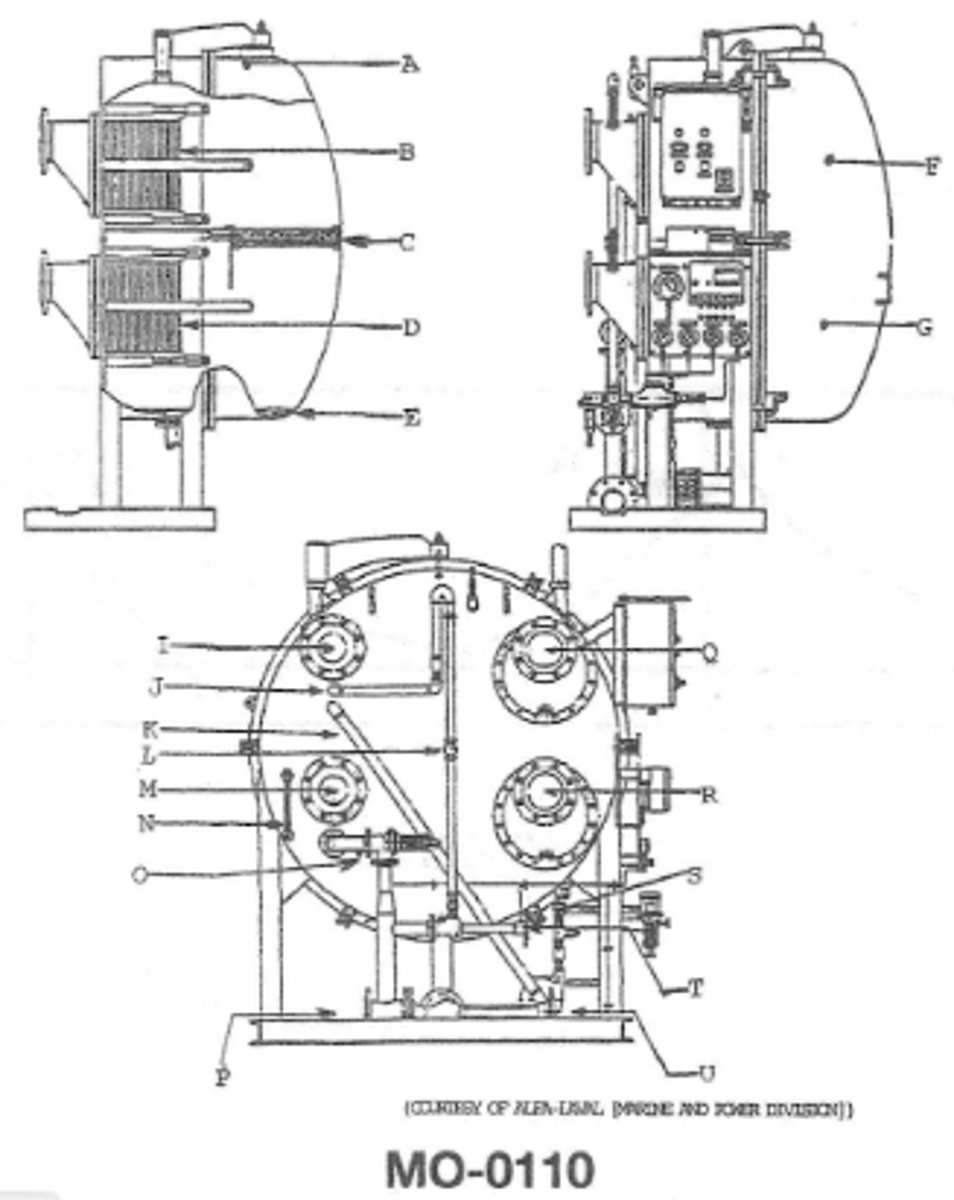
what is the function of C (MO-0110)
removes moisture entrained in the vapors produced in G
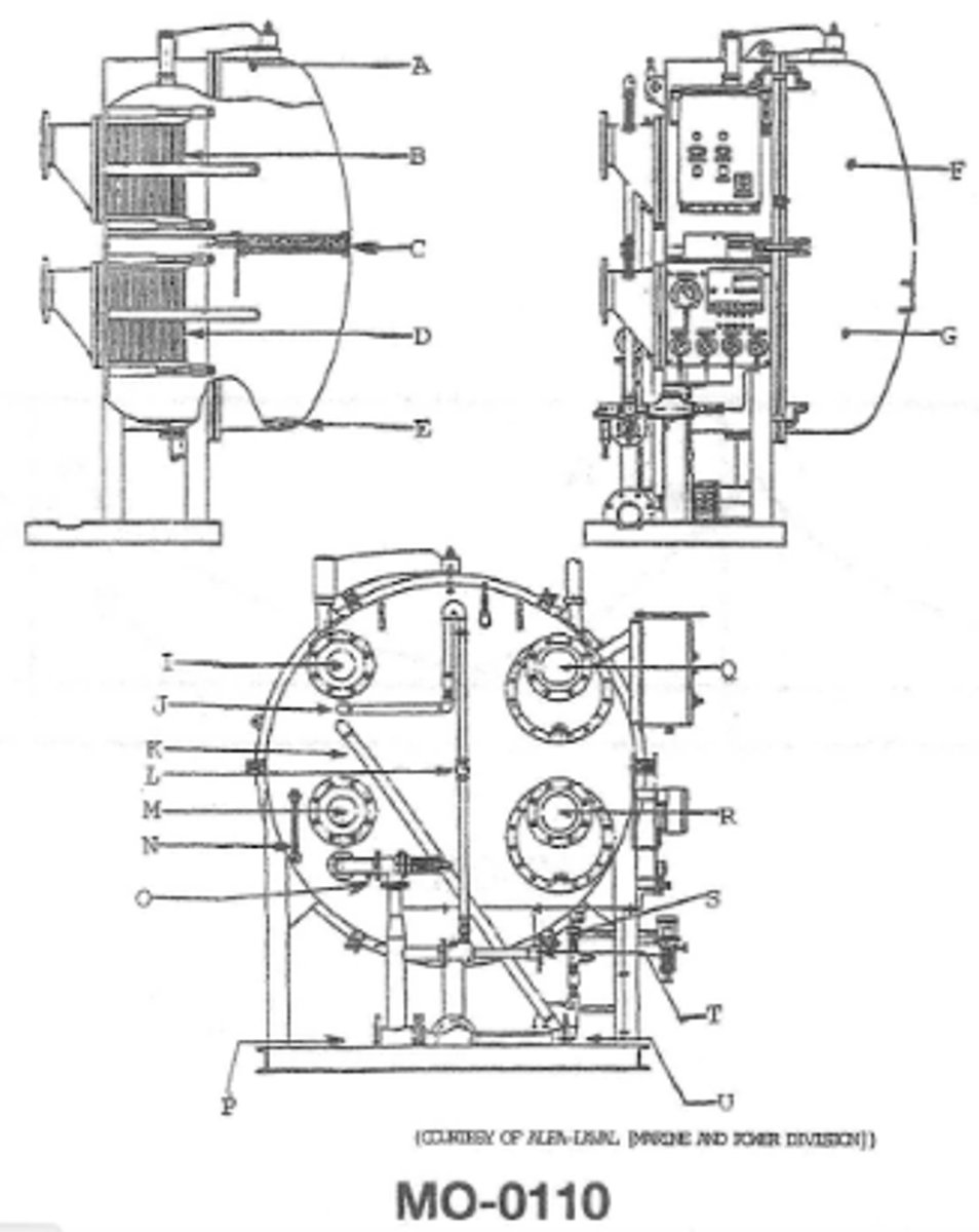
What occurs in D(MO-0110)
the feed water enters the device and vaporizes under vacuum conditions
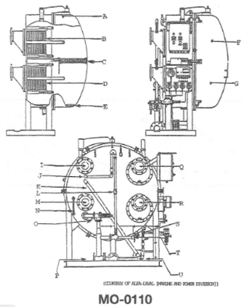
Line K is the (MO-0110)
distillate pump suction
When responding to a "right rudder" command from the amidships position which parts of the steering gear system illustrated will be subjected to the highest pressure?GS-0137
"E" and "B"
3 multiple choice options
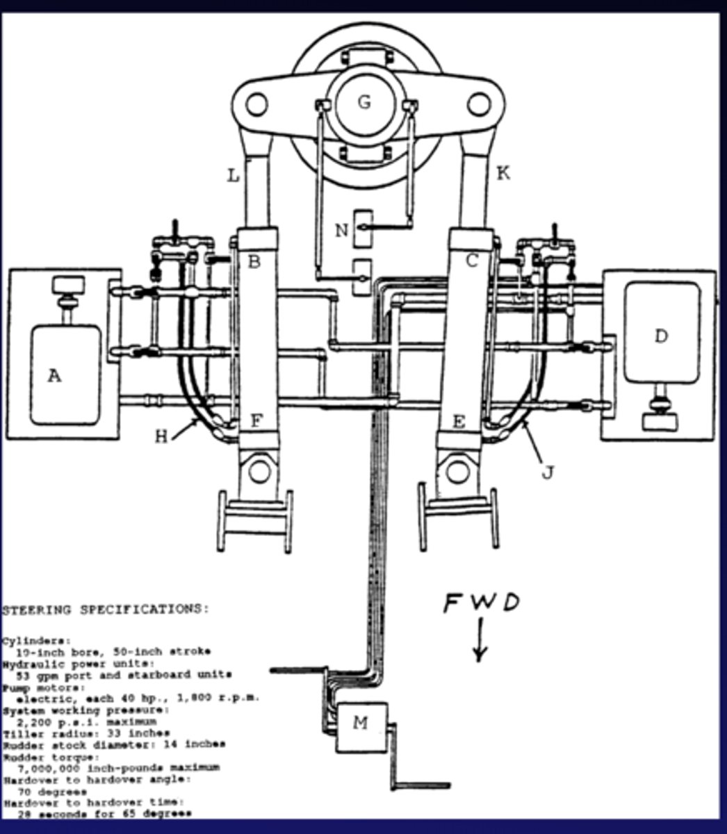
When responding to a "left rudder" command from the amidships position which parts of the steering gear system illustrated will be subjected to the highest pressure?GS-0137
"C" and "F"
3 multiple choice options
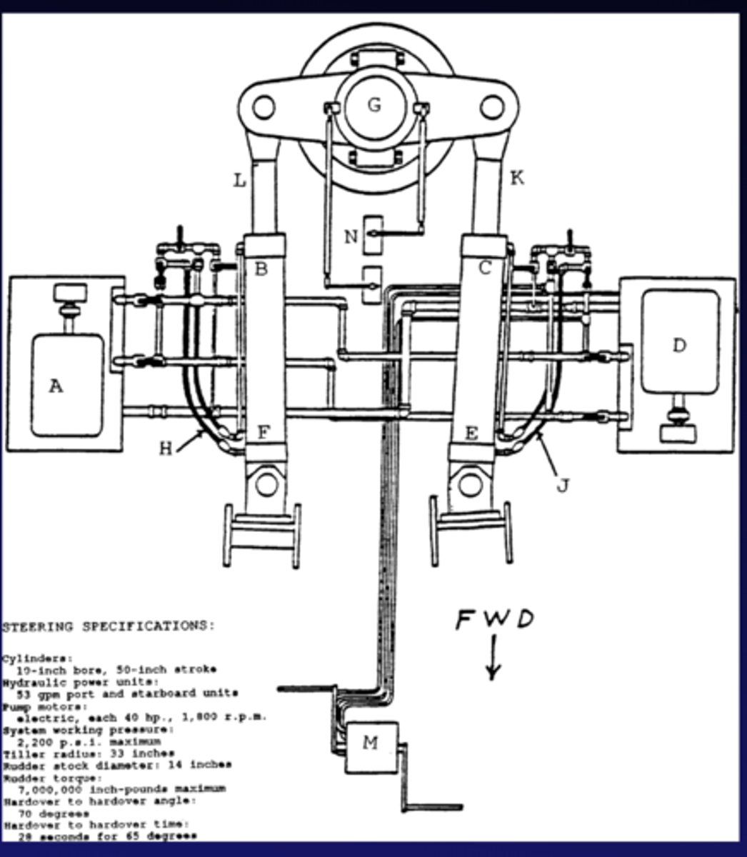
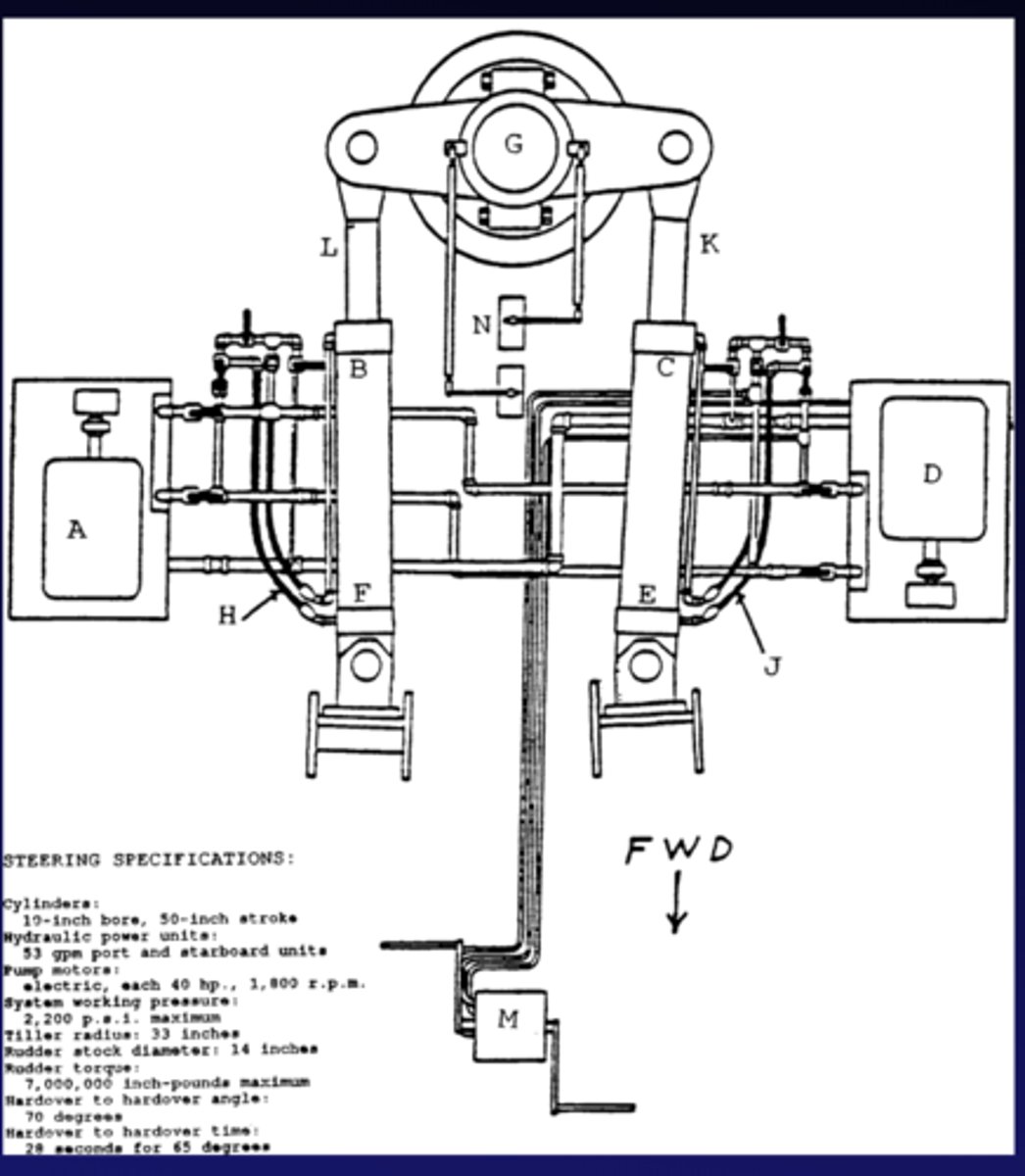
Which of the following action will occur with the steering system shown in the illustration when responding to a left rudder command from amidships?GS-0137
the starboard ram will extend aft
3 multiple choice options
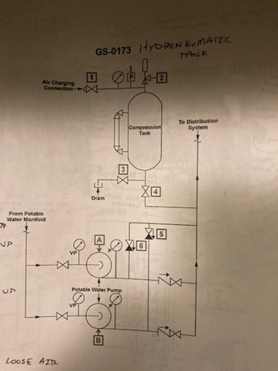
Which of the following conditions is most likely to cause water hammer in the potable water system shown in the illustration? GS-0173
Loss of air in the hydro-pneumatic tank
3 multiple choice options
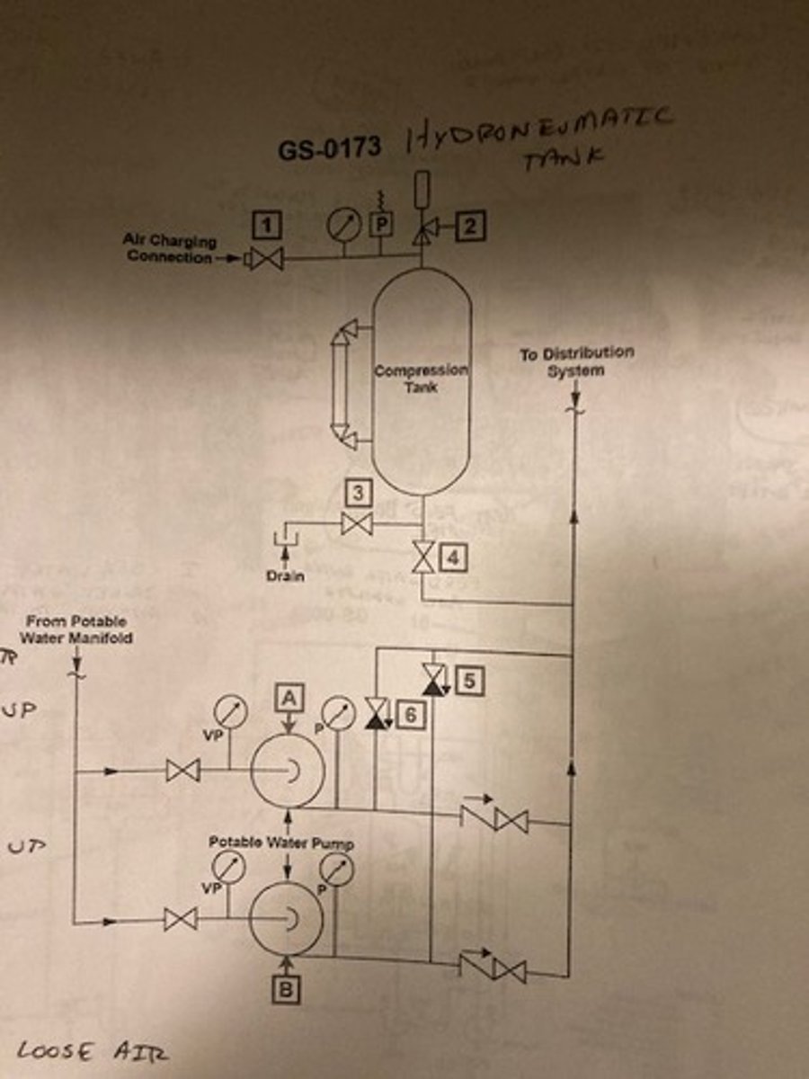
According to the illustration which of the following conditions would most likely cause pump "A" to short cycle? GS-0173
The hydro-pneumatic expansion tank is operating with an insufficient air charge
3 multiple choice options
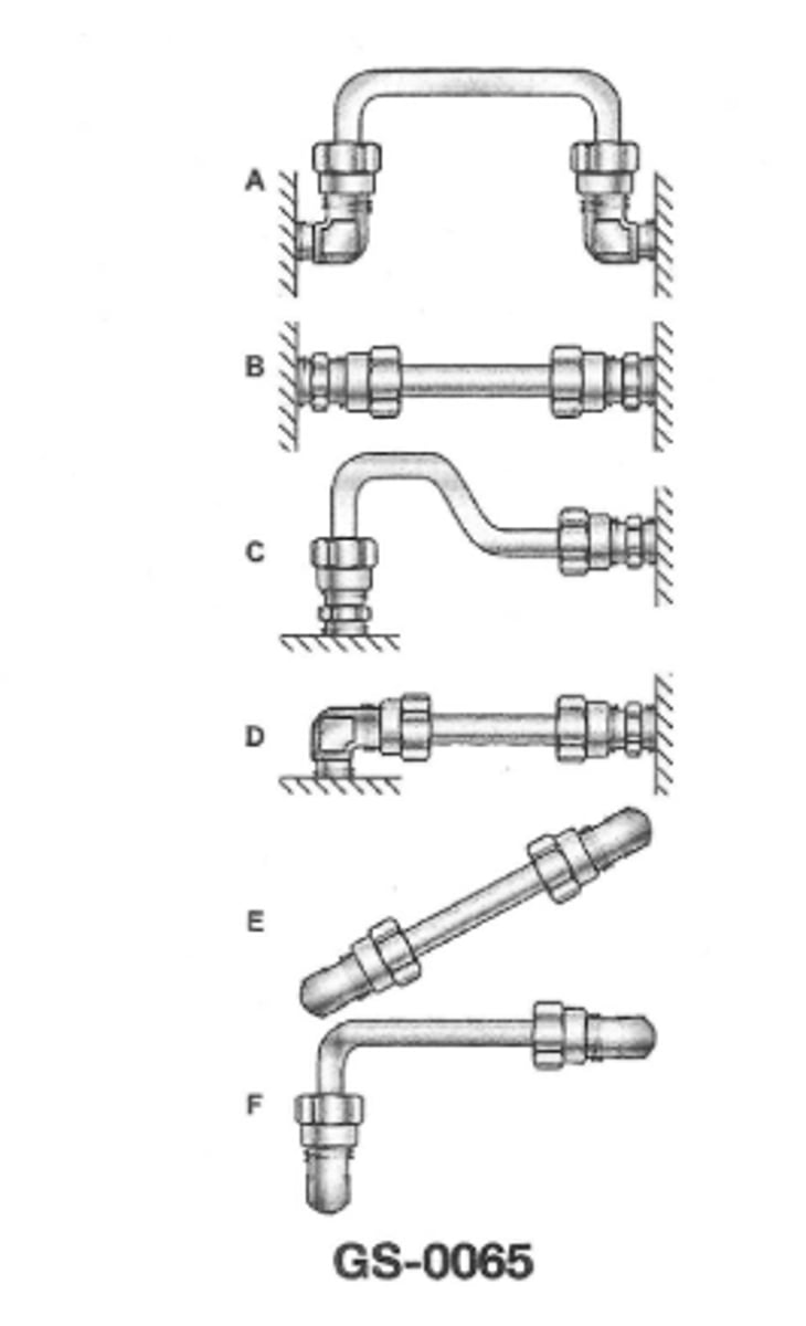
The hydraulic tubing installation shown as figure D in the illustration will probably leak when operating because the tubing___ GS-0065
has no provision to compensate for strain due to expansion and contraction
3 multiple choice options
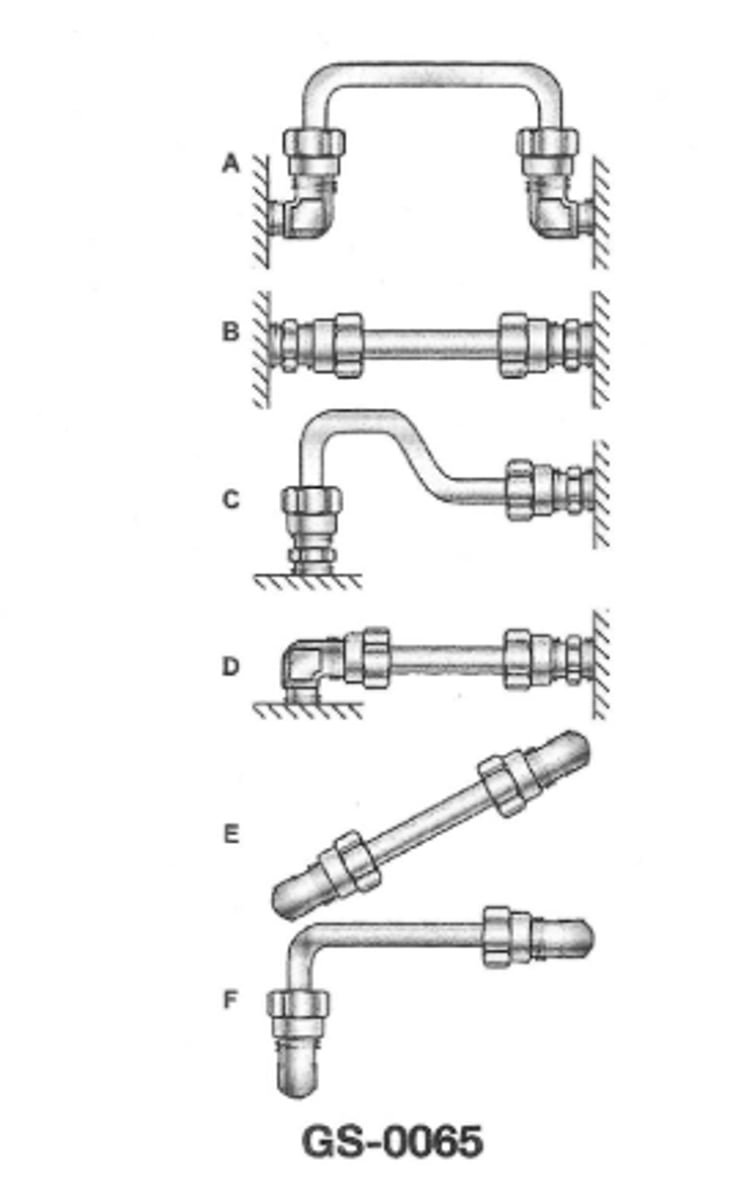
which of of the listed illustrations shows the INCORRECT method for installing hydraulic tubing?GS-0065
D
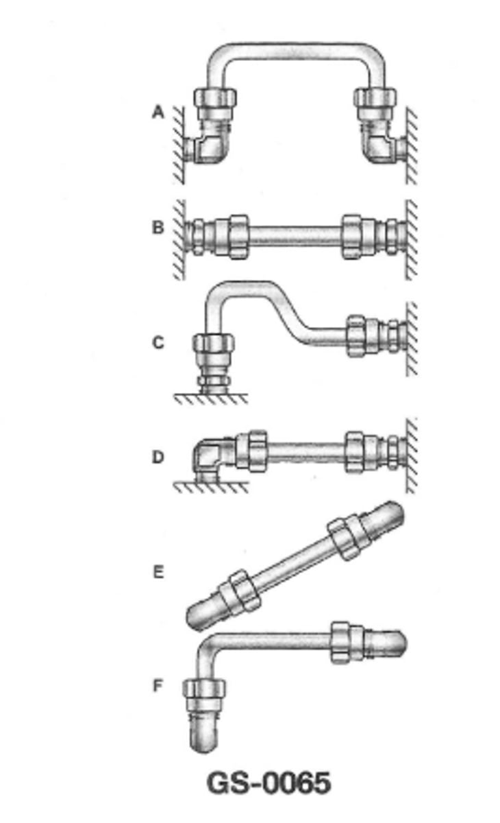
The hydraulic tubing installation shown as figure "D" is INCORRECT and will probably leak when in operation because the tubingGS-0065
and its fitting cannot be properly installed and tightened
The rudder torque capacity of the four ram steering gear illustrated is rated at 44210000 inch-pounds with one power unit in operation. If the four ram system was able to be operated as a two ram system with both power units on line what would be the available torque?GS-0067
22105000
3 multiple choice options
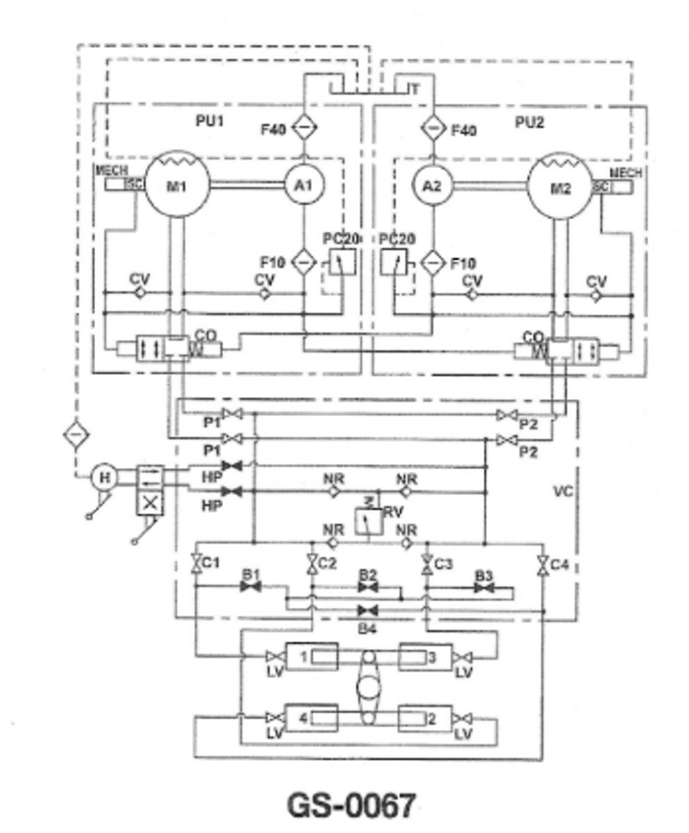
Which of the valve arrangements listed can be used to modify the four ram hydraulic steering gear system shown in the illustration to a working two ram system?GS-0067
Close valves "C2" "C4" and open valves "B2" "B4"
3 multiple choice options
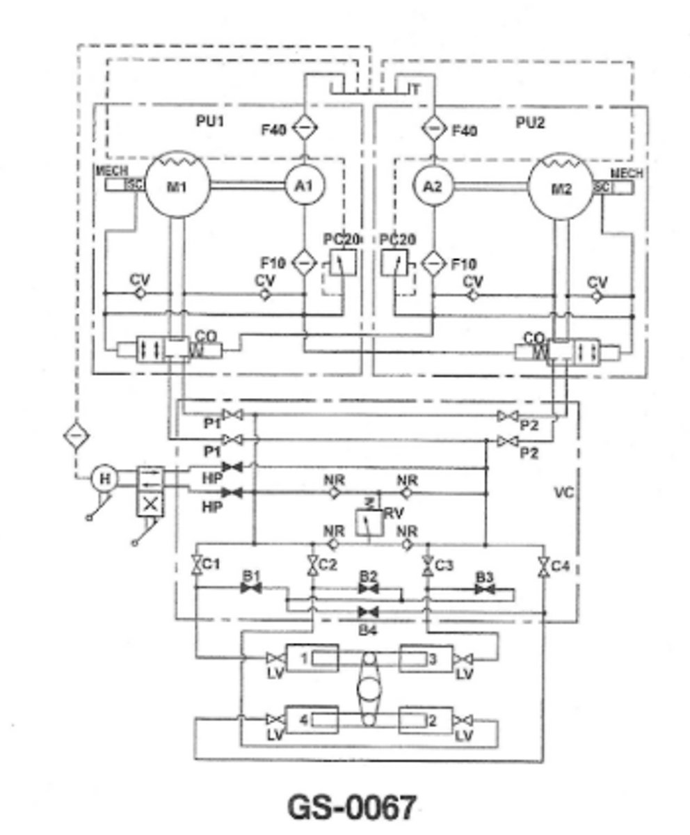
Assuming valve "A" is correctly aligned in the no-flow position as shown with the system in operation which of the following statements is true?GS-0049
Valve "D" would normally open before valve "B".
3 multiple choice options
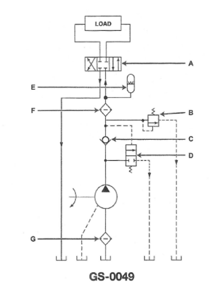
Valve "D" in the illustration is referred to as a GS-0049
unloading valve
3 multiple choice options
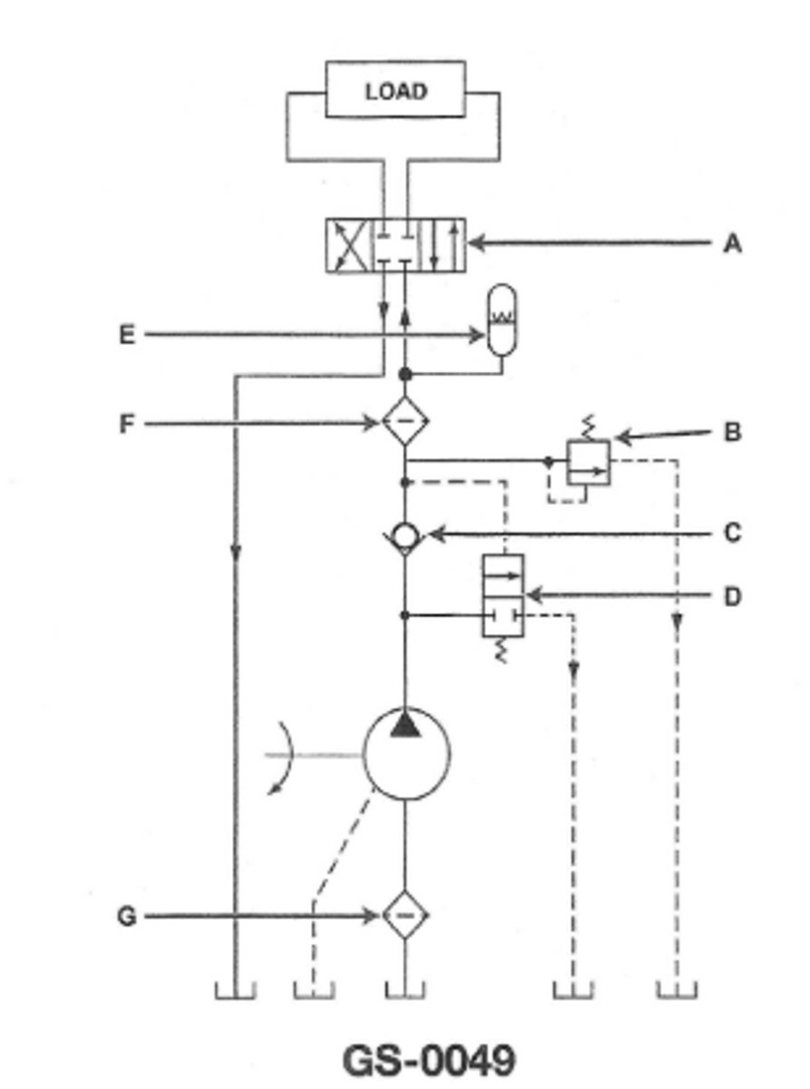
The dashed line to the illustrated pump is theGS-0049
casing drain
3 multiple choice options
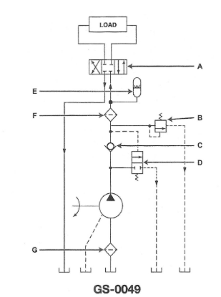
If solenoid "B" of the valve illustrated is energized the cylinder willGS-0041
retract with rate of movement controlled
3 multiple choice options
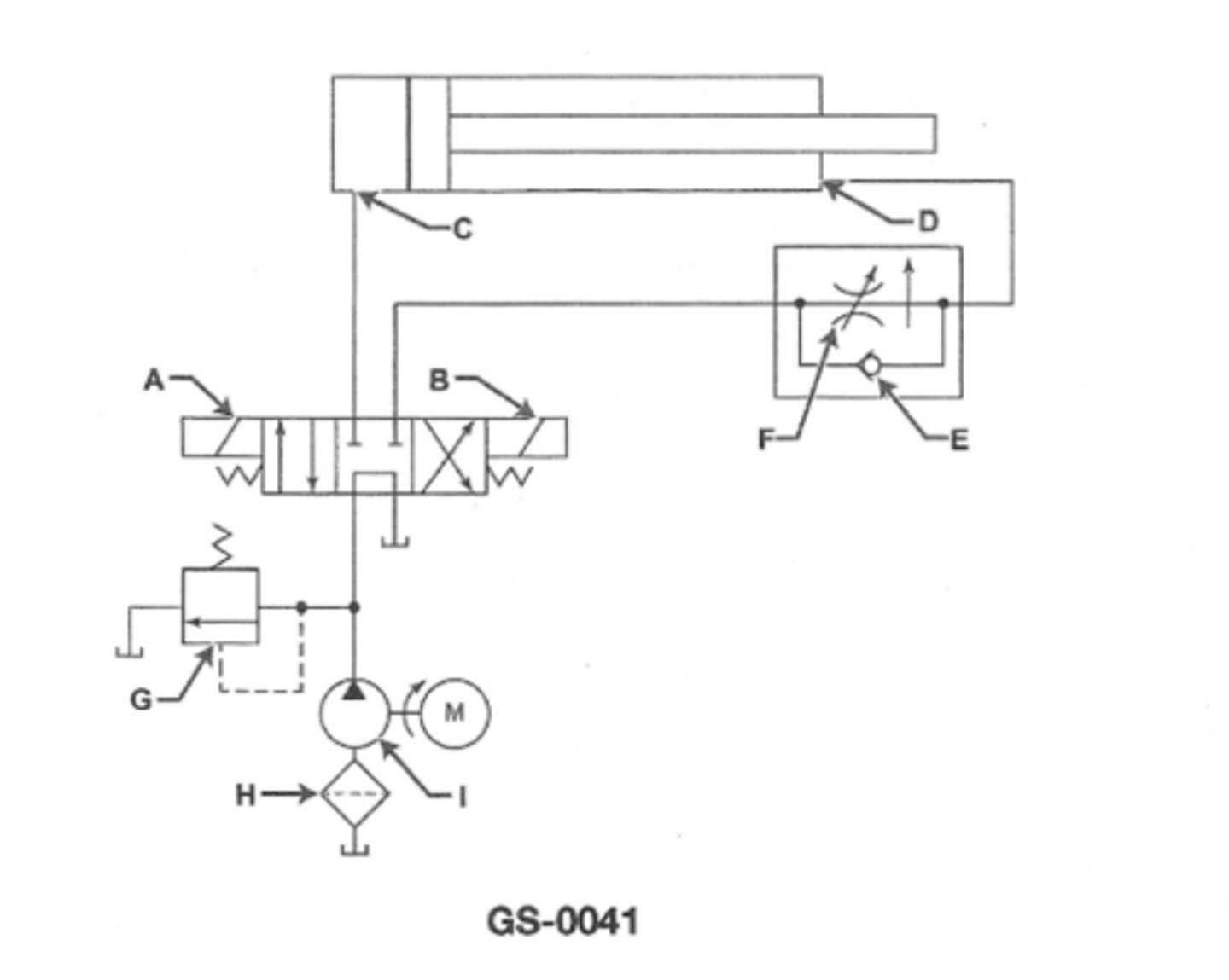
Which of the following is true concerning the hydraulic system illustratedGS-0041
All above
3 multiple choice options
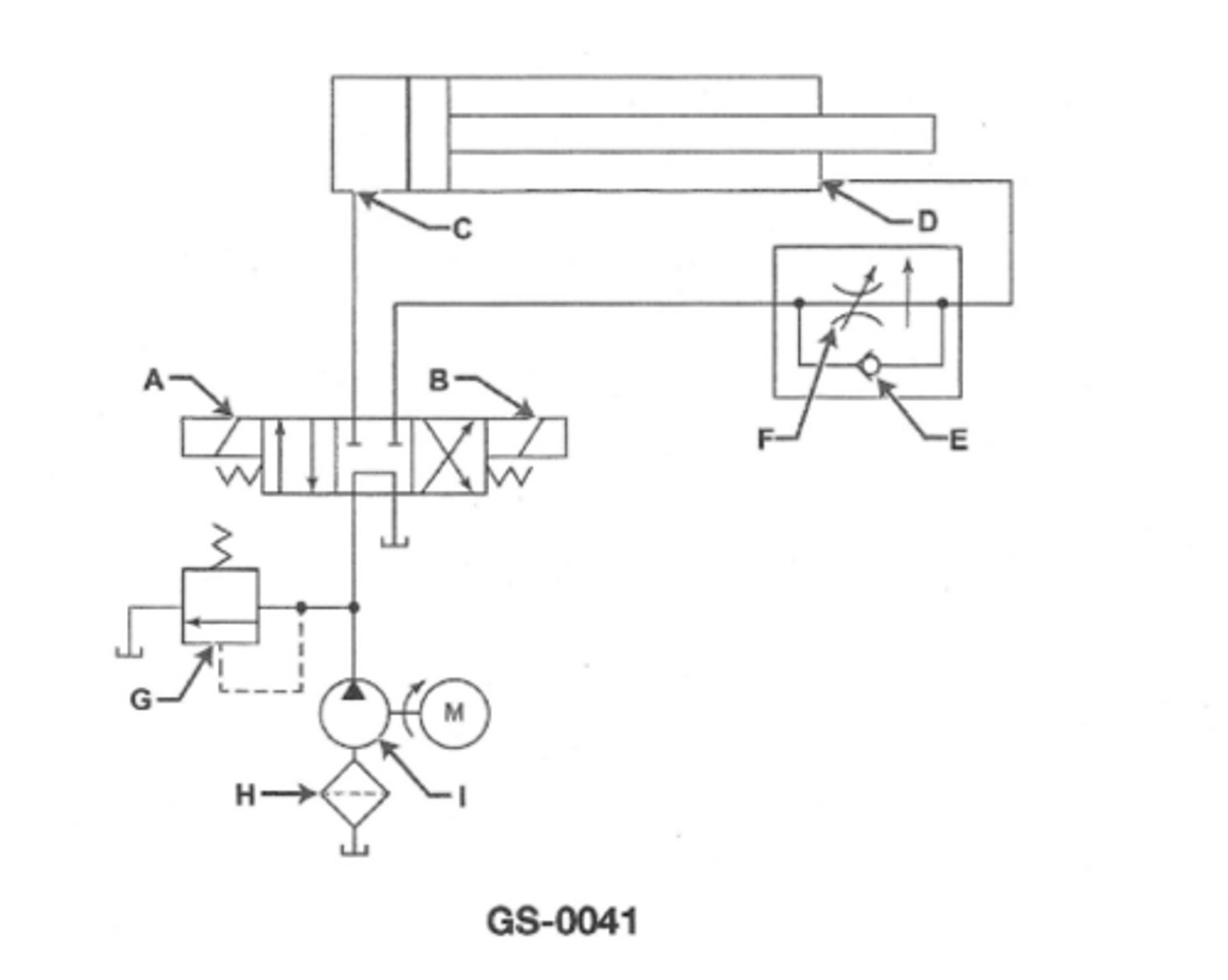
If solenoid "B" illustrated is energized theGS-0041
cylinder should retract
3 multiple choice options
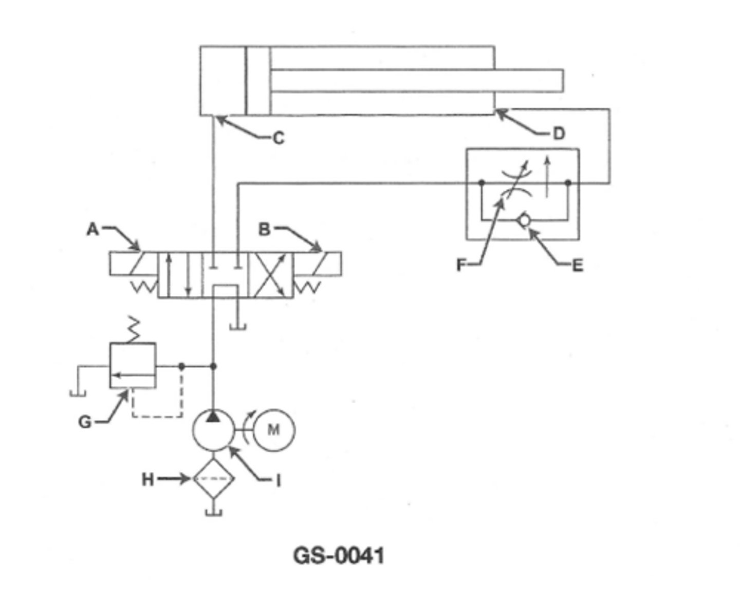
If solenoid "A" illustrated is energized theGS-0041
cylinder should extend
3 multiple choice options
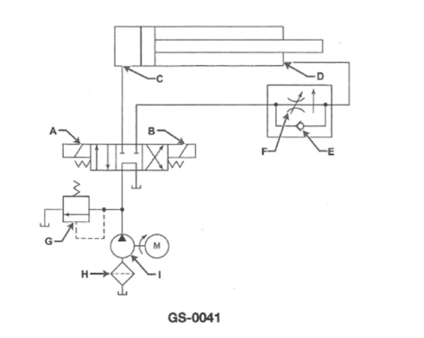
In the hydraulic schematic illustrated the pump symbol indicated the us of aGS-0041
constant flow pump of indefinite construction
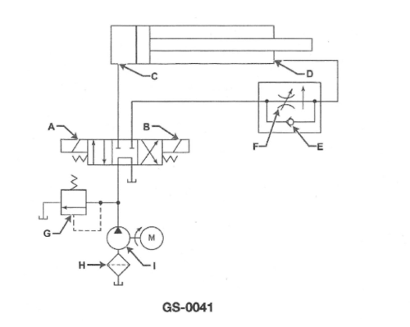
Which of the following is true concerning the hydraulic system illustratedGS-0041
The piston rod will extend at a faster rate than retracts
3 multiple choice options
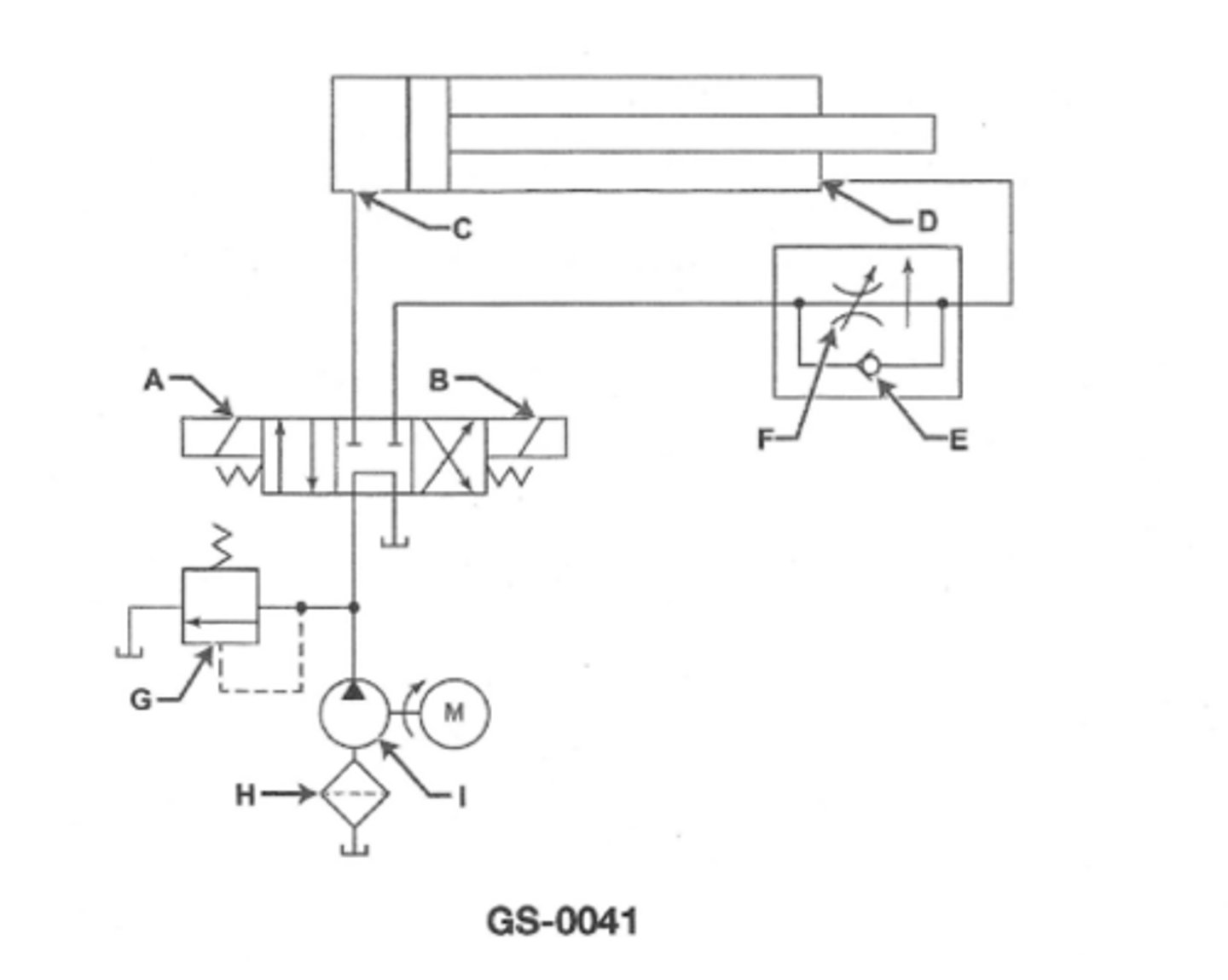
Which of the following components listed is shown in the illustration?GS-0041
filter
3 multiple choice options
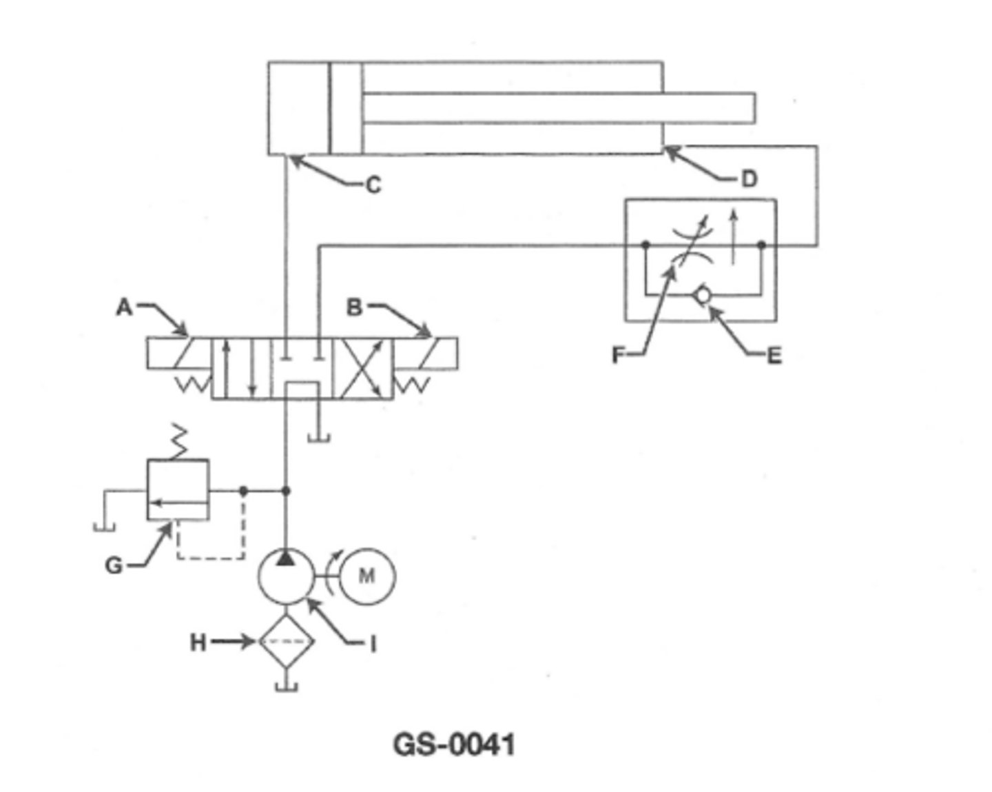
If solenoid "A" of the valve illustrated is energized the cylinder willGS-0041
extend with rate of movement uncontrolled
3 multiple choice options
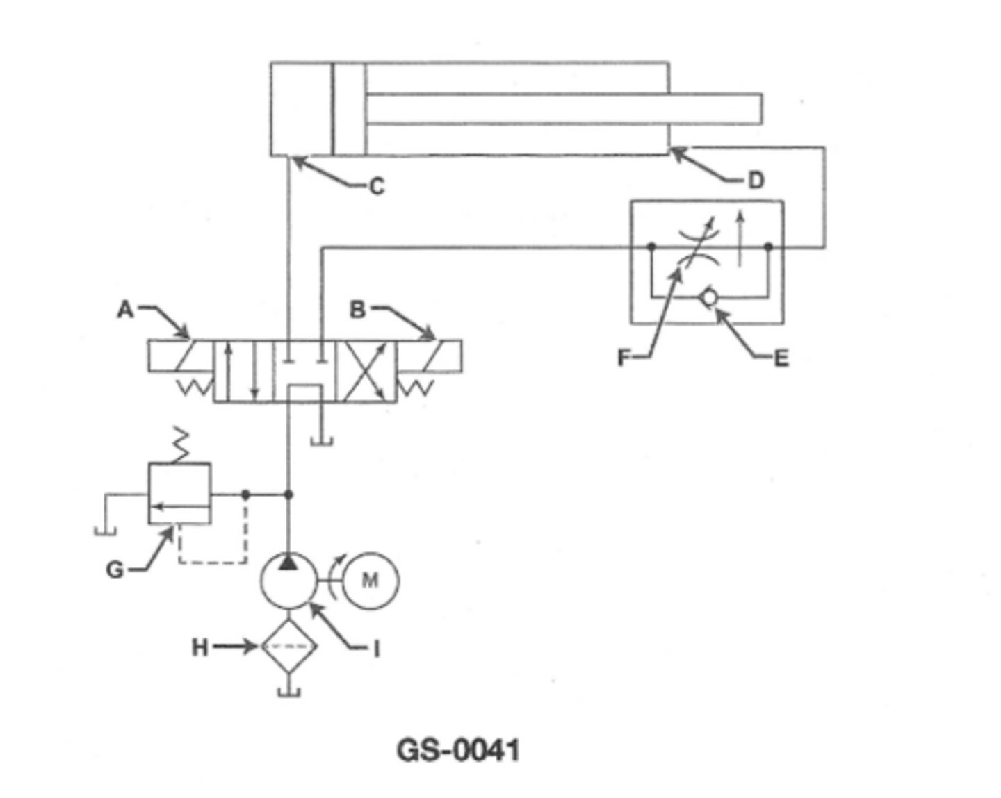
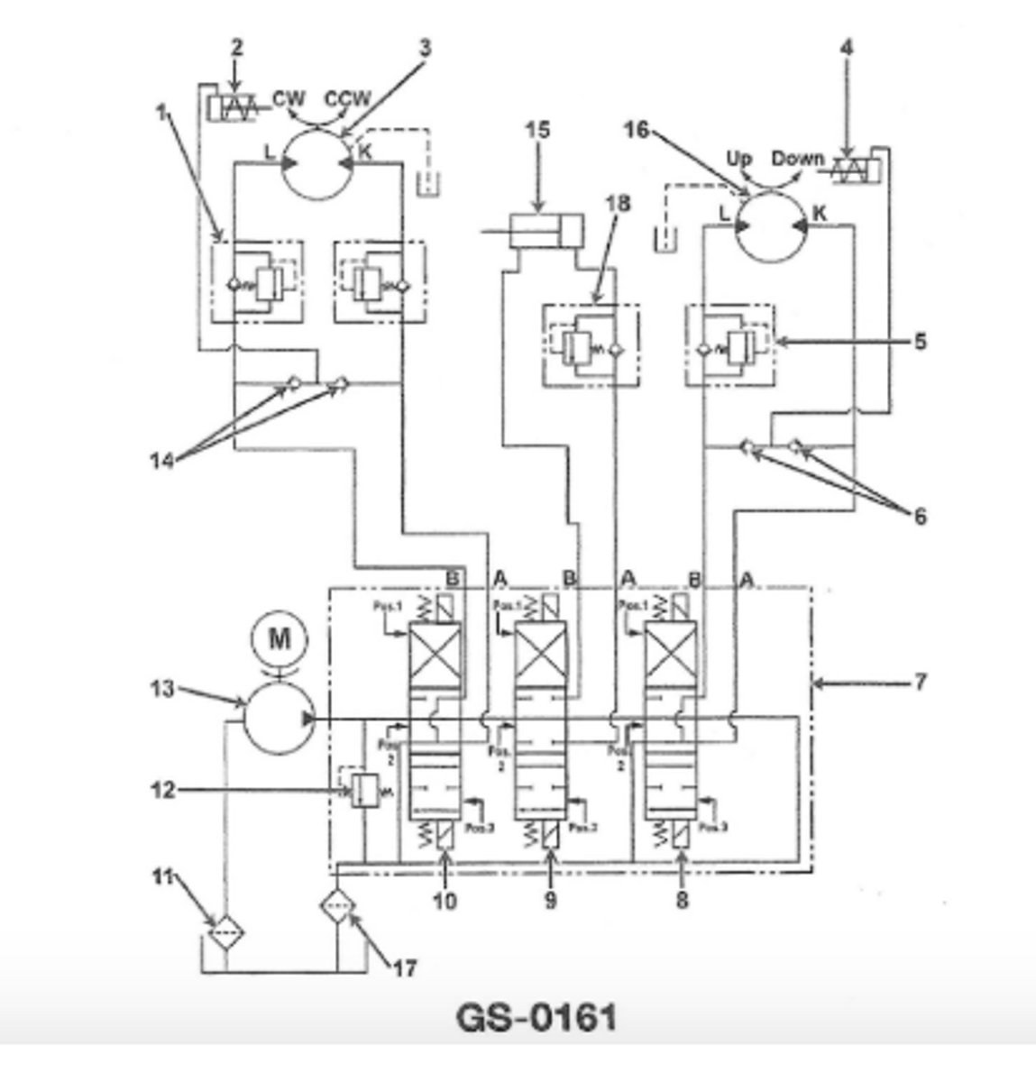
The counter balance valve (5) in the winch circuit shown in the illustrationGS-0161
helps prevent slung loads from dropping prematurely
3 multiple choice options
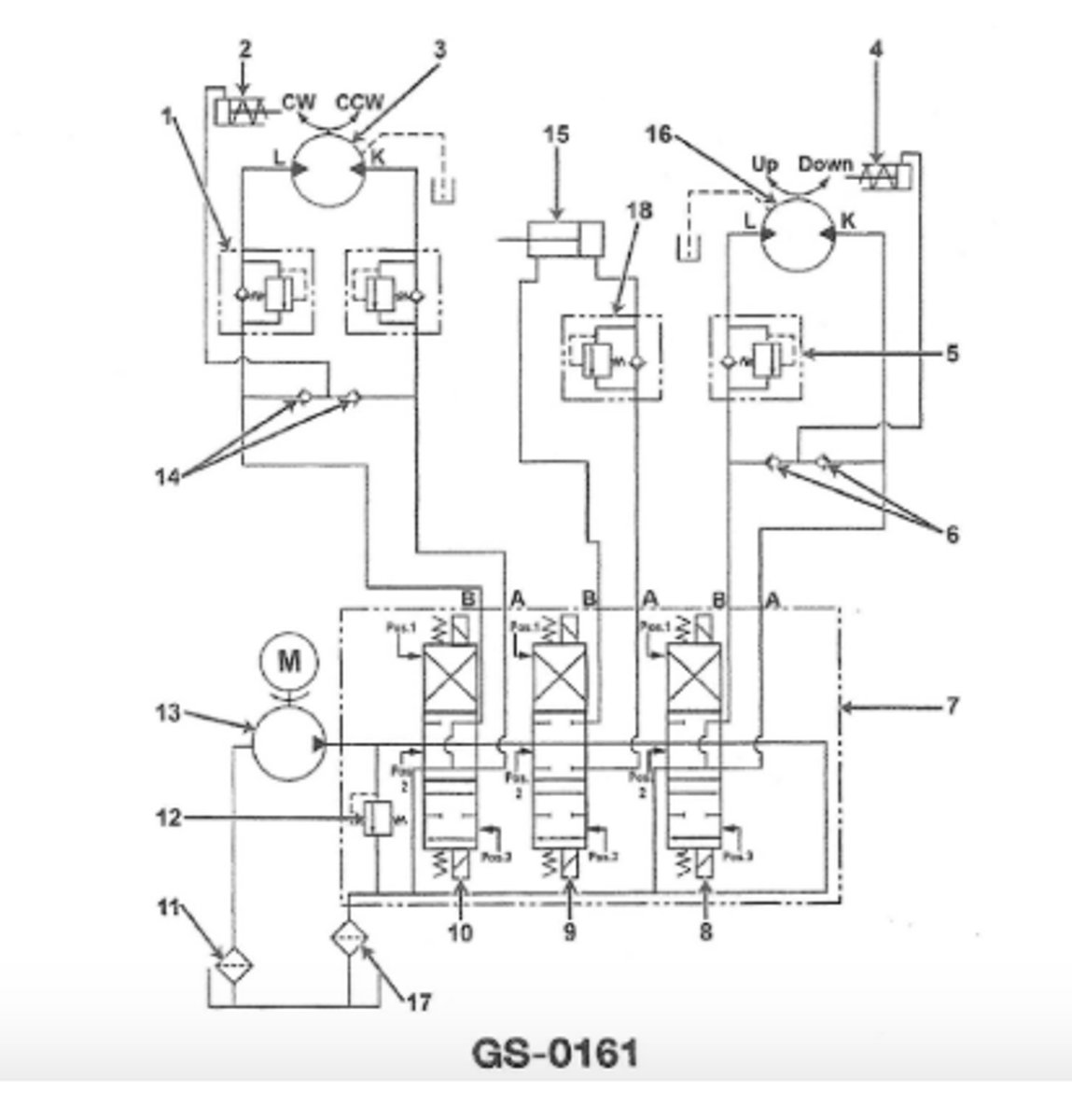
The direction and rate of rotation for the cab in the hydraulic crane circuit shown is controlled by theGS-0161
manual control valve (item #10)
3 multiple choice options
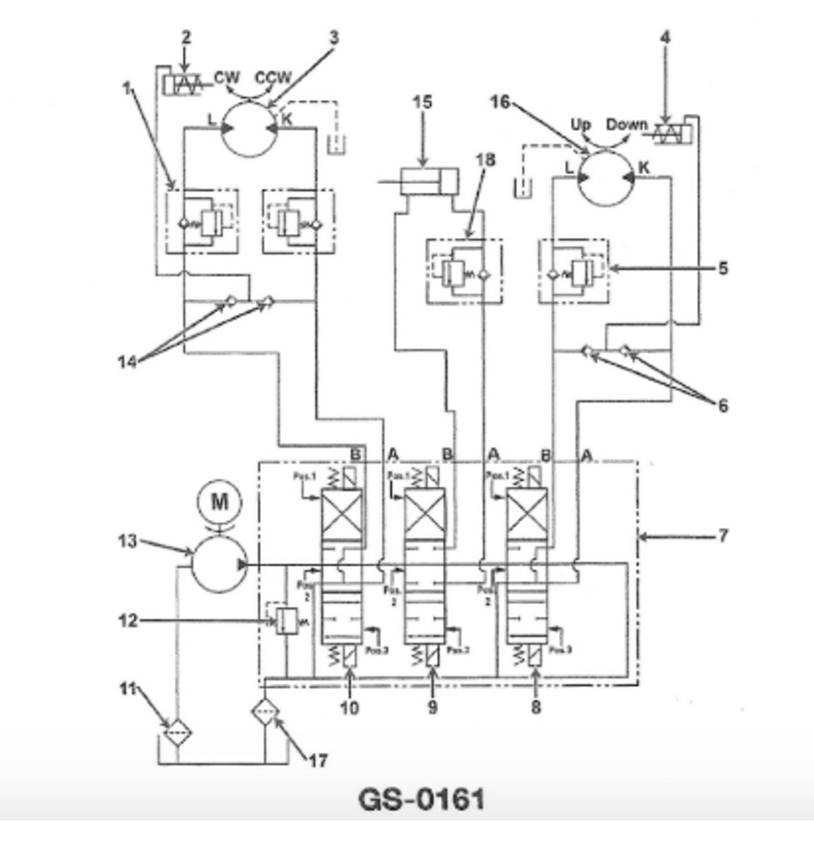
if the boom shown in the illustration can be raised but not lowered the problem is most likely with the "Topping circuit"GS-0161
counterbalance valve
3 multiple choice options
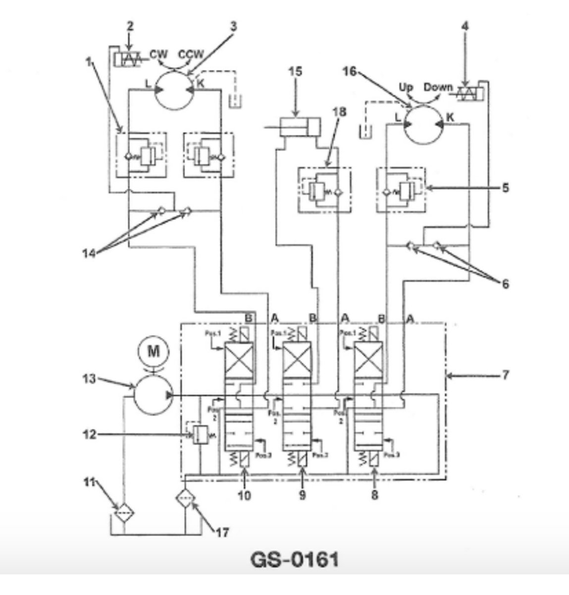
The safety feature which assists the hydraulic crane circuit illustrated to maintain the required boom angle is a function of itemGS-0161
18
3 multiple choice options
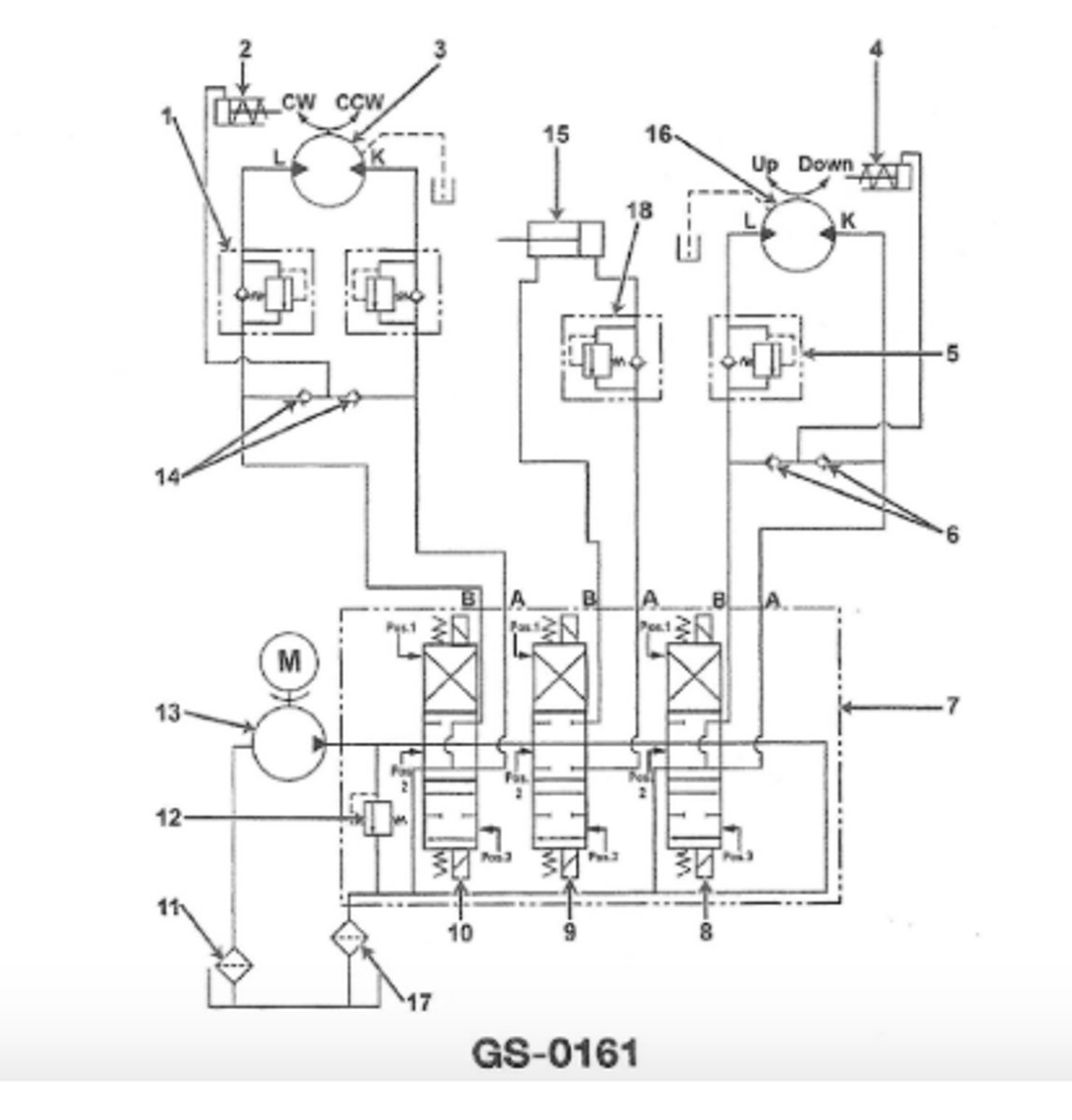
The directional control valves as shown in the illustration areGS-0161
three-position spring loaded and open centered
3 multiple choice options
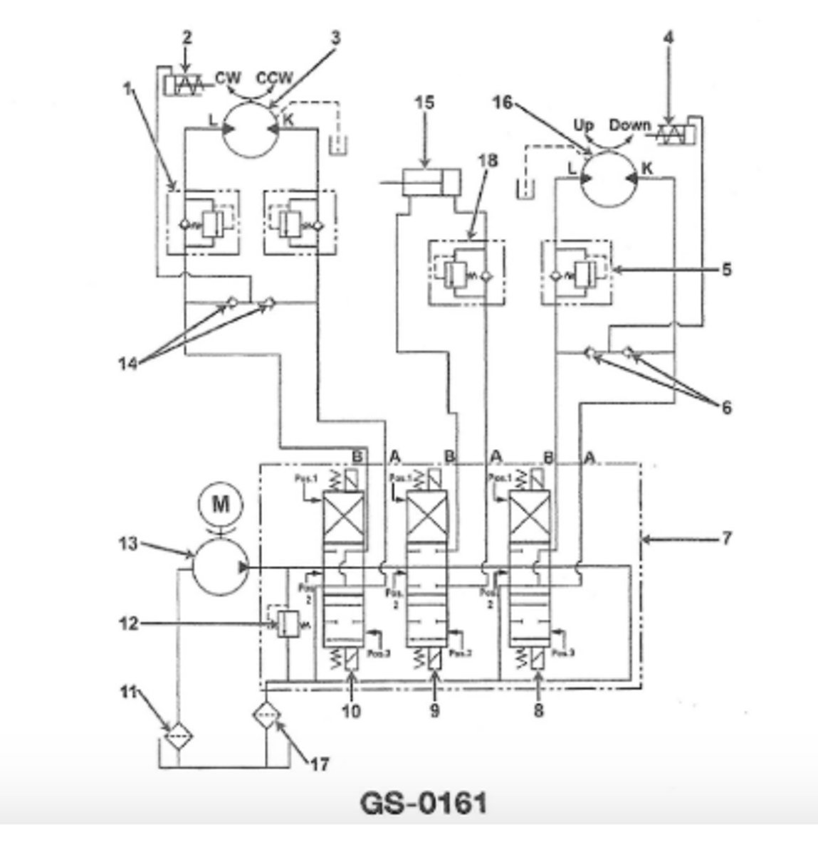
If the operating pressure is determined to be normal in the system shown in teh illustration yet the crane does not swing(slew) in either direction when the directional control valve is operated the problem could be GS-0161
an obstruction in the brake release cylinder line(2)
3 multiple choice options
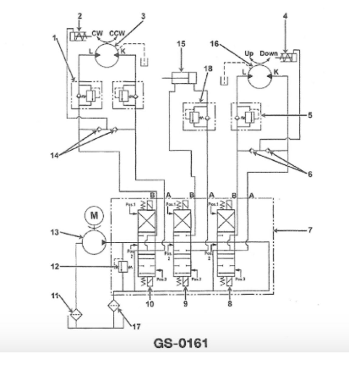
In the hydraulic crane circuit illustrated which would be the correct hydraulic configuration required to raise the boom?GS-0161
activate directional valve 9 and shift spool valve to area 1
3 multiple choice options
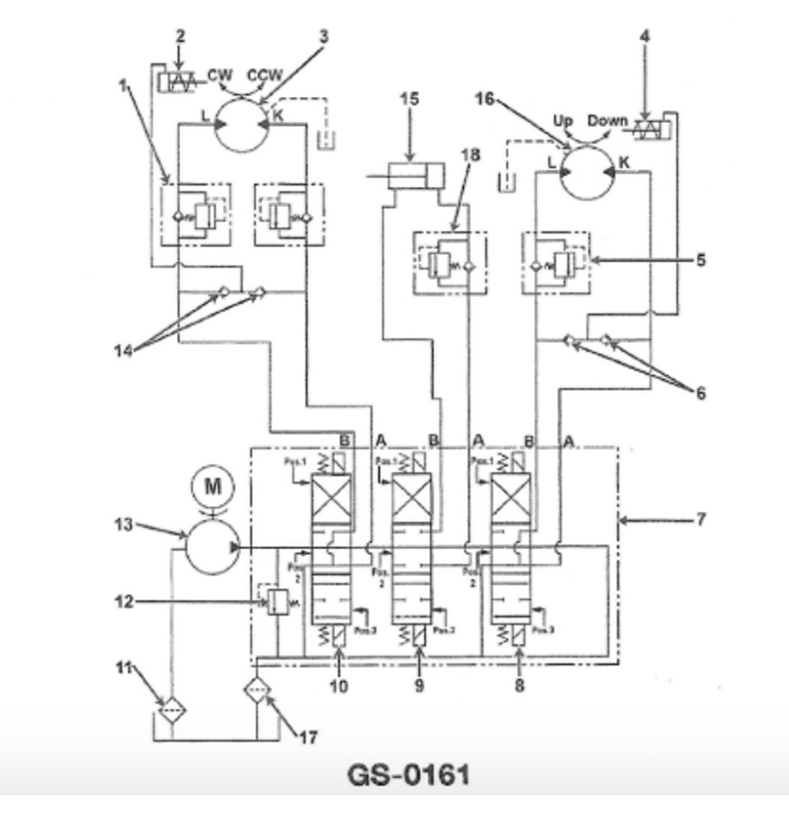
Which component in the illustrated hydraulic crane circuit acts to prevent the wire rope drum from accidentally paying out?GS-0161
4 and 5
3 multiple choice options
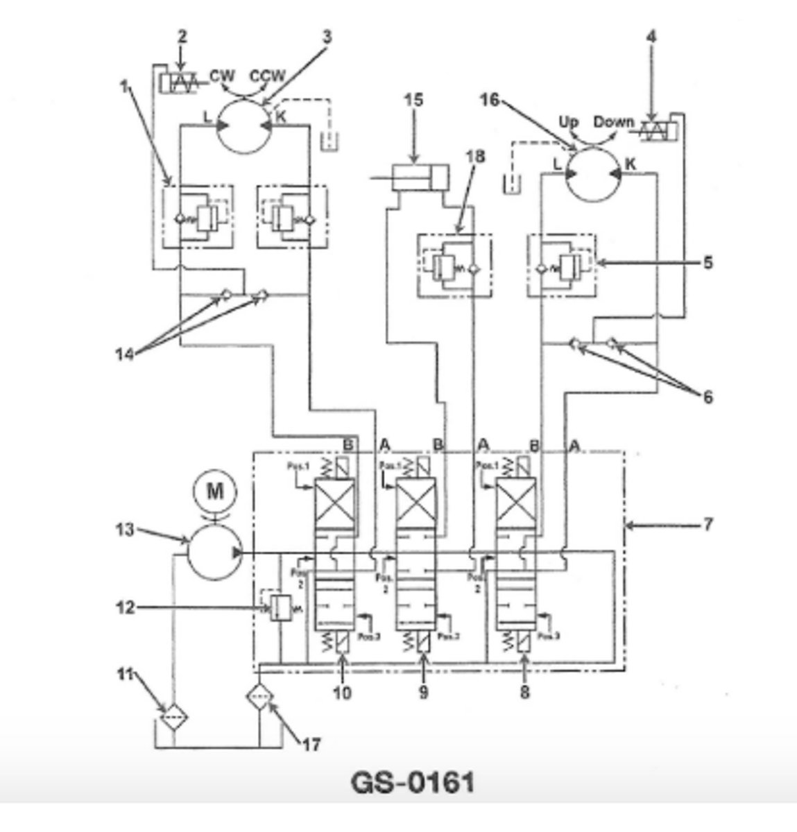
In the hydraulic crane circuit illustrated what is the function of the component labeled 18GS-0161
provide additional control when lowering boom
3 multiple choice options
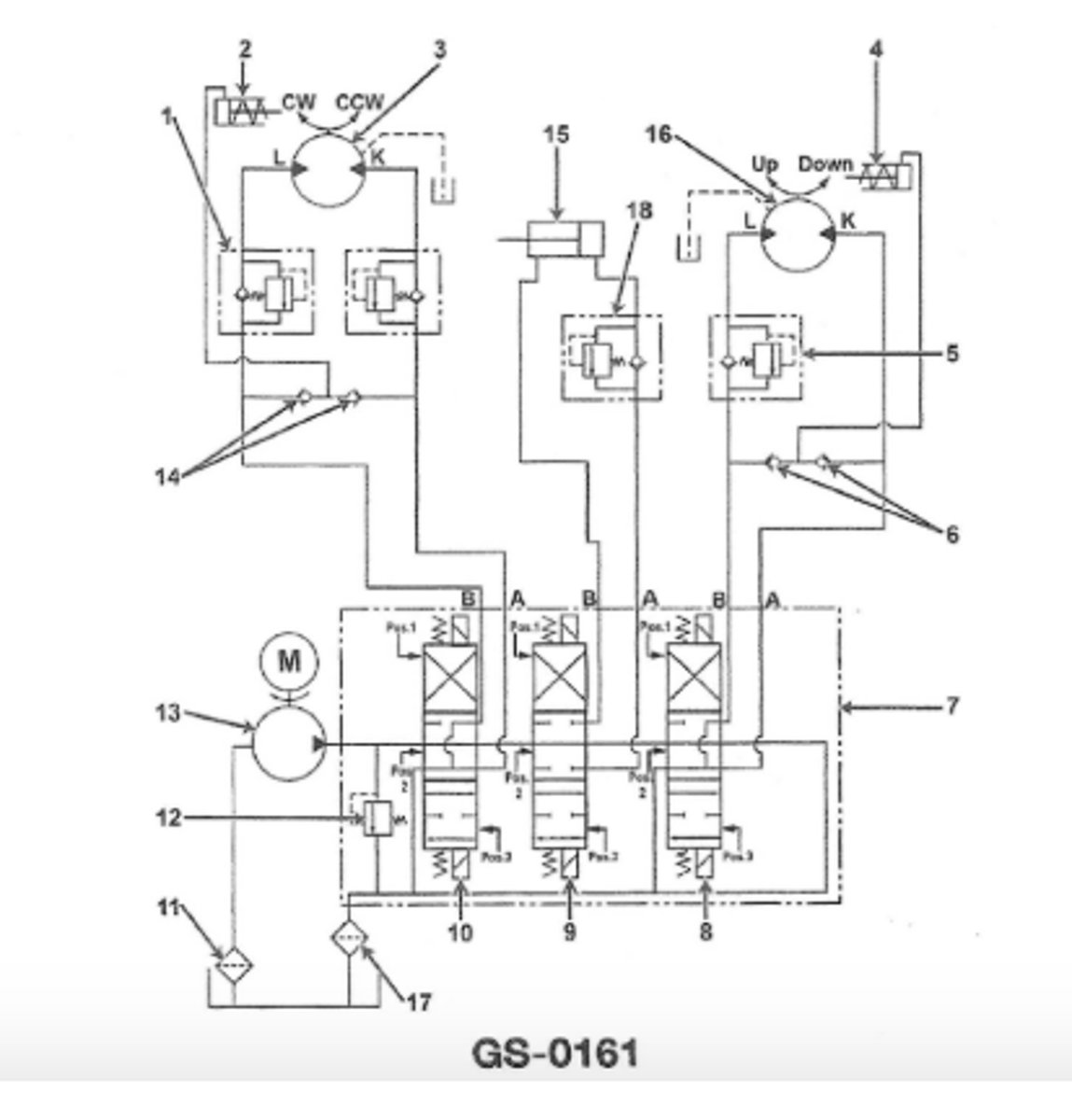
The wire rope drum used in the illustrated hydraulic crane circuit is prevented from accidentally paying out byGS-0161
components labeled 4 and 5
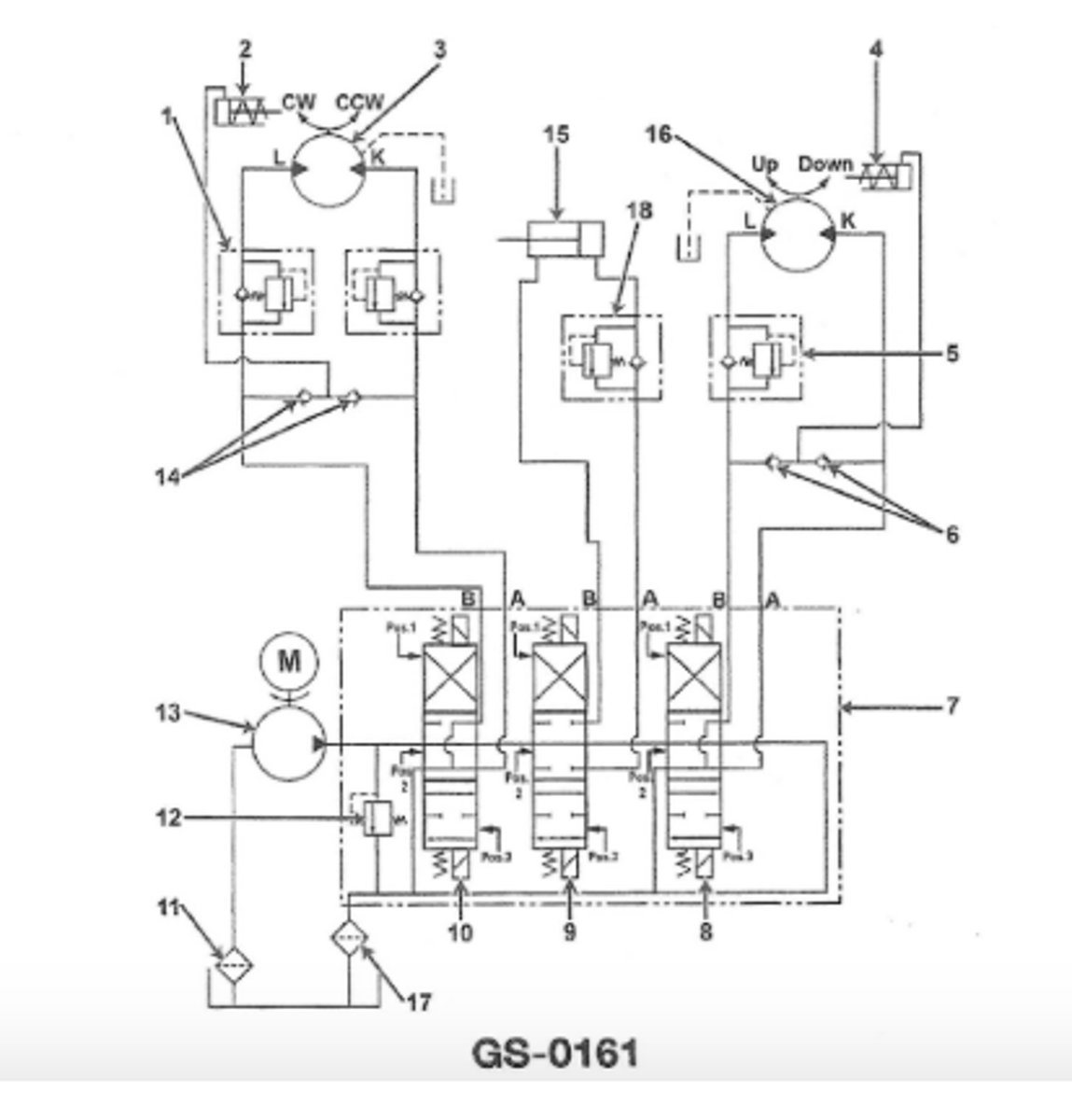
You press the start button on the hydraulic power unit shown in the illustration and the motor does not start the first thing you should check is the(GS-0161)
controller circuit breaker
The hydraulic graphic symbol illustrated in Fig. B is used to represent a GS-0068
variable orifice
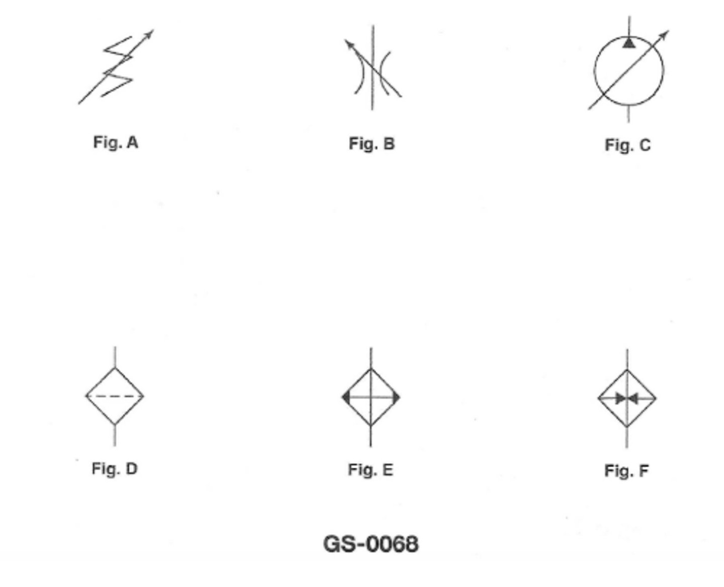
The hydraulic graphic symbol illustrated in Fig. C is used to represent a GS-0068
variable output single direction flow pump
The hydraulic graphic symbol illustrated in Fig. A is used to represent a GS-0068
spring
An arrow superimposed on a hydraulic graphic symbol at approximately 45°, as shown in the illustrated figures A, B, and C, indicates the component __________. See illustration GS-0068.
can be adjusted or varied
3 multiple choice options
In the steering gear unit shown in the illustration which of the actions listed will occur as "left rudder" is being attained? GS-0104
Ram cylinder "A" is under hydraulic pressure
3 multiple choice options
The steering gear unit shown in the illustration which of the condition listed will occur as "left rudder" is being obtained and only the "No.1" steering gear pump is running? GS-0104
Cylinder end "H" is under pressure
3 multiple choice options
In the steering gear system shown in the illustration if the maximum working pressure is applied to the face of the ram the total force on one piston will be___ GS-0104
209230
2 multiple choice options
While responding to a right full rudder command from the amidships postion which of the cylinders illustrated will be fully pressurized on the face of the pistons? GS-0104
E
3 multiple choice options
Which of the following figures is INCORRECT regarding the direction of flow and shaft rotation for the lobe type pump shown? GS-0179
B
3 multiple choice options