CompSystems 245 - Week 5 - Lecture 13 - Timers and Counters pt 2
 Call Kai
 Learn
Learn Practice Test
 Spaced Repetition
 Match
Match Flashcards
 Knowt Play
1/13

There's no tags or description
Looks like no tags are added yet.
Name | Mastery | Learn | Test | Matching | Spaced | Call with Kai | Chat |
|---|
No analytics yet
Send a link to your students to track their progress
14 Terms
Describe PWM:
What it is
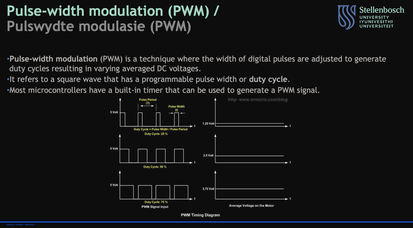
Describe PWM on STM32F4:
how to generate them
how to affect frequency
how to affect duty cycle
what the CNT and CCRx registers are doing
the modes that can be generated
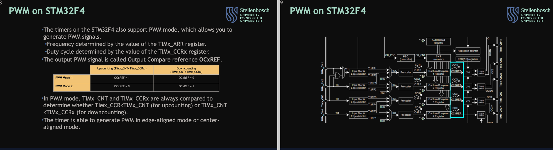
Draw a timing graph in PWM Mode 1 (Low-True):
Upcounting mode
ARR = 6
CCR = 3
RCR = 0
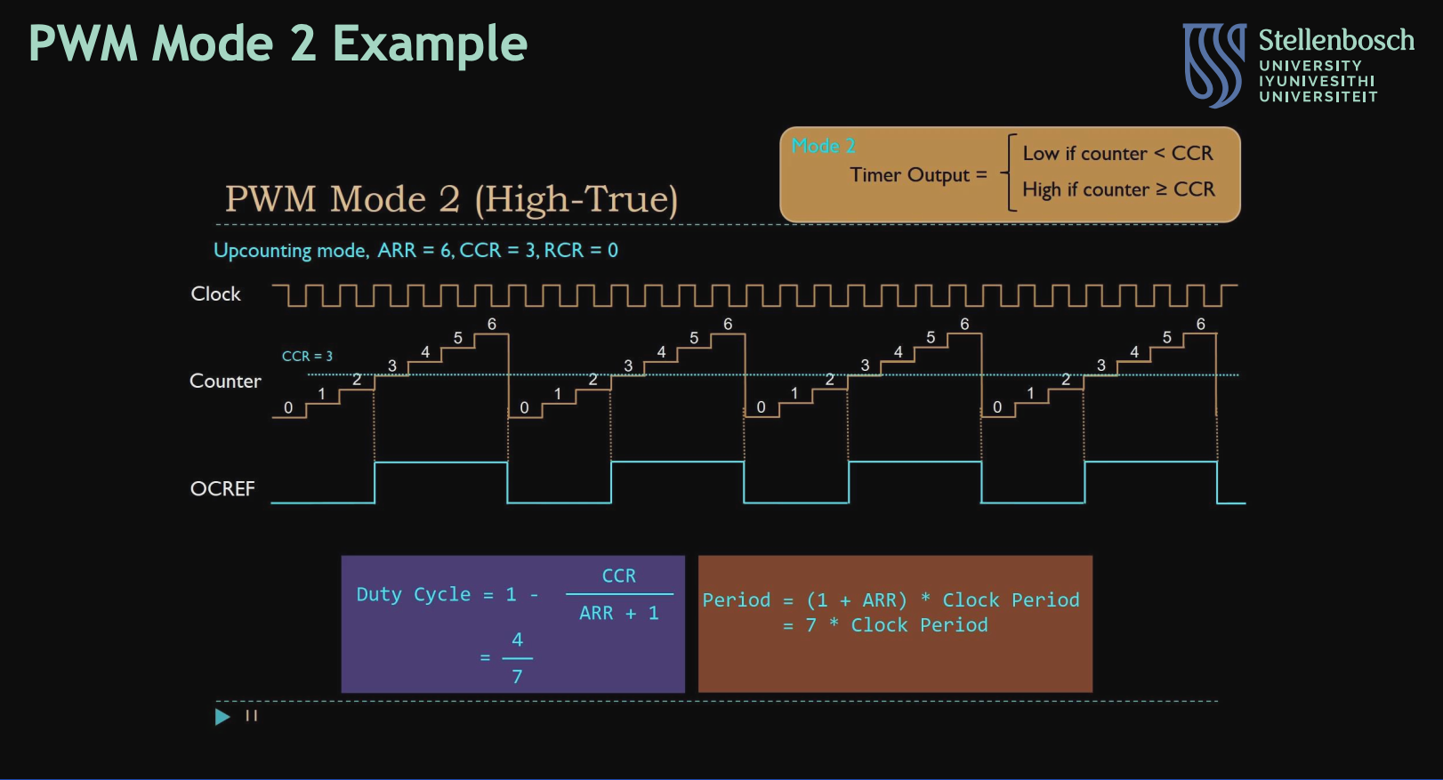
Draw a timing graph in PWM Mode 1 (High-True):
Upcounting mode
ARR = 6
CCR = 3
RCR = 0
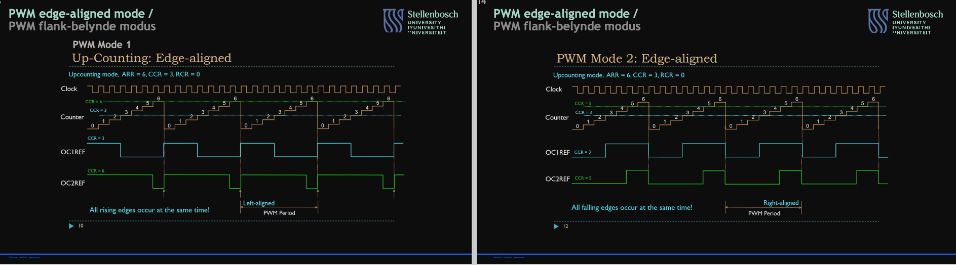
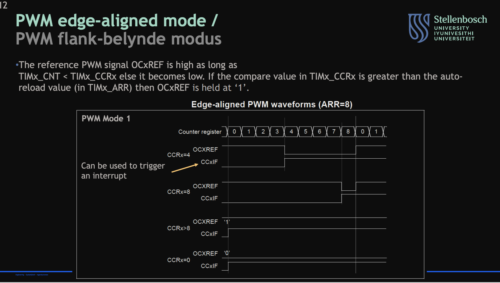
Describe the PWM in edge-aligned mode:
what it means
counter diagram
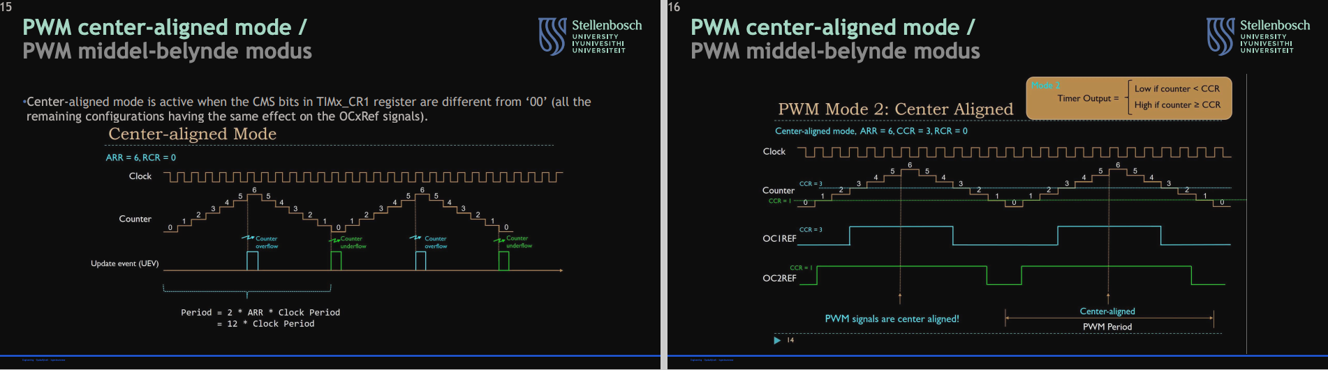
Describe the PWM in center aligned mode:
What that means
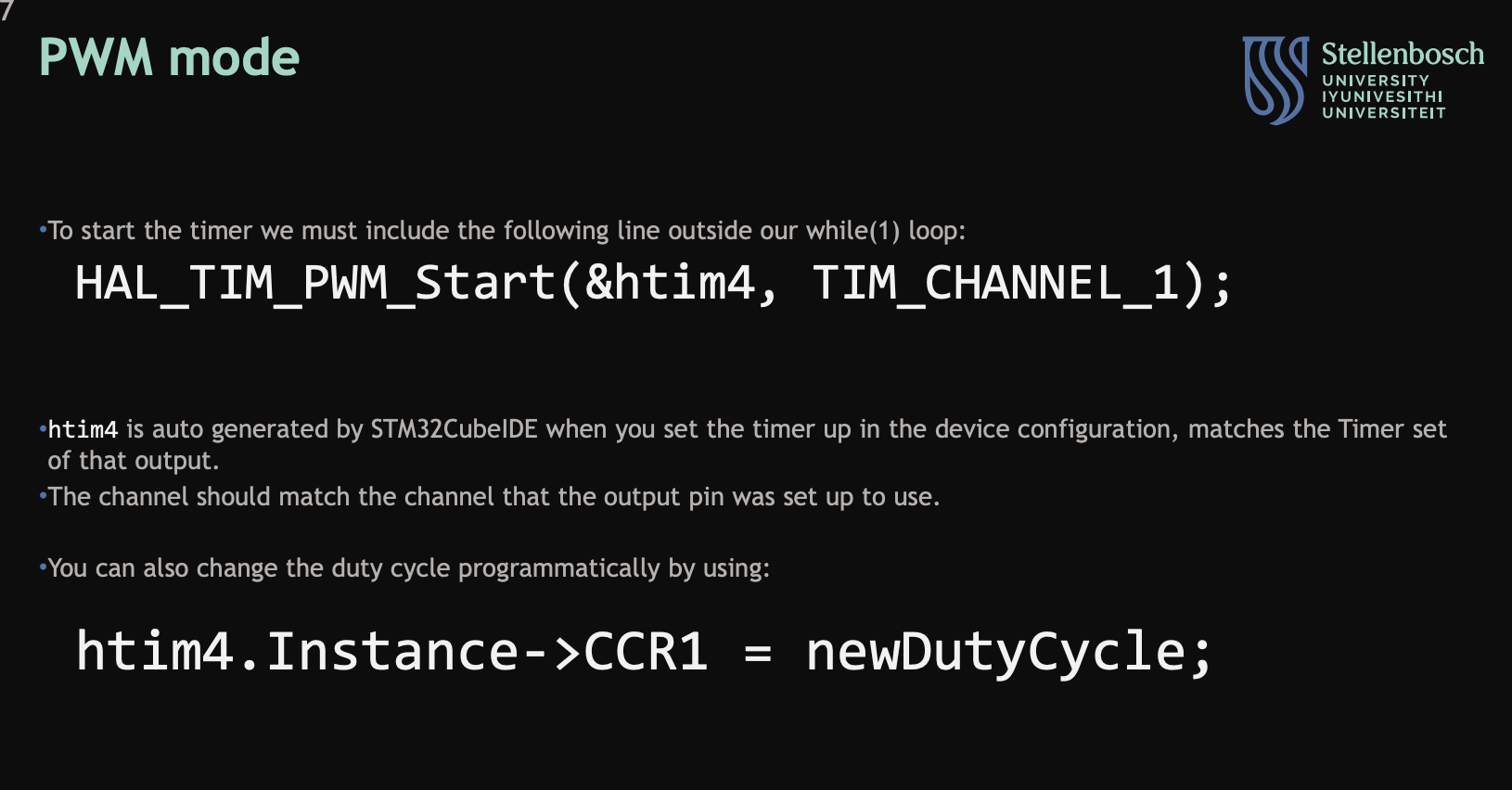
Describe how to use PWM mode in STMCube32IDE:
its function
how to change duty cycle programmatically
Describe one pulse mode:
what it is

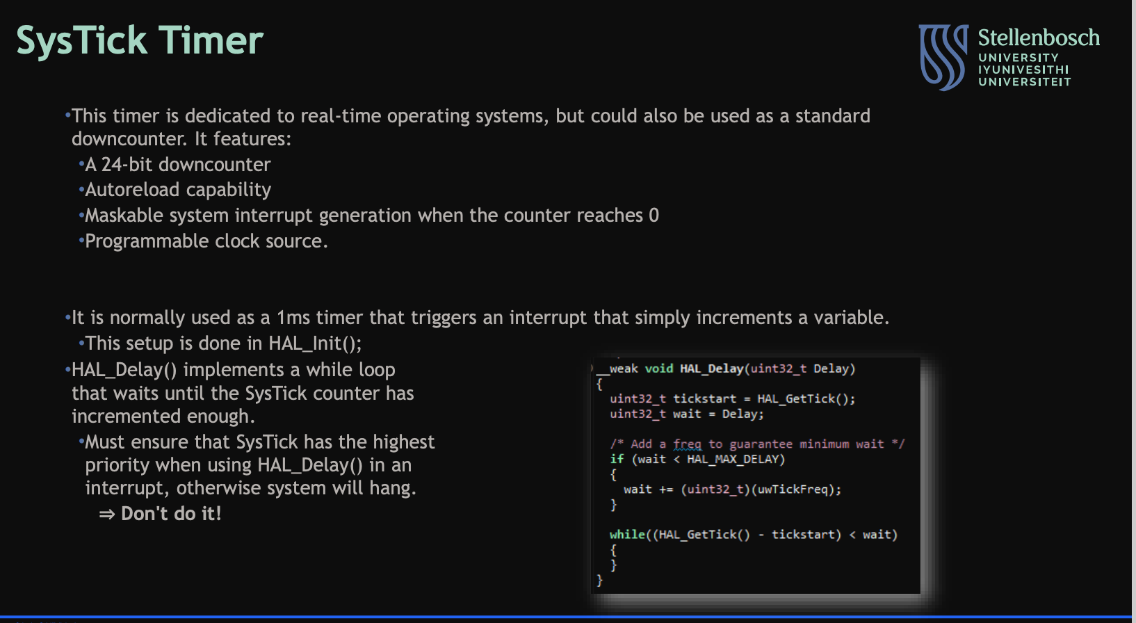
Describe the SysTick Timer:
what it is
its features
what its used fore
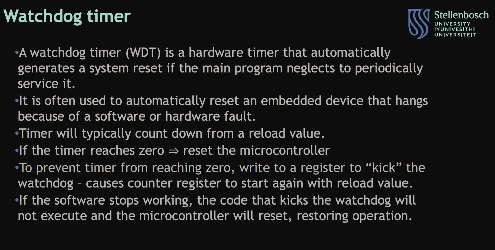
Describe the Watchdog timer:
what it is
what it does
its uses
Describe the watchdog timer:
the types
what they do
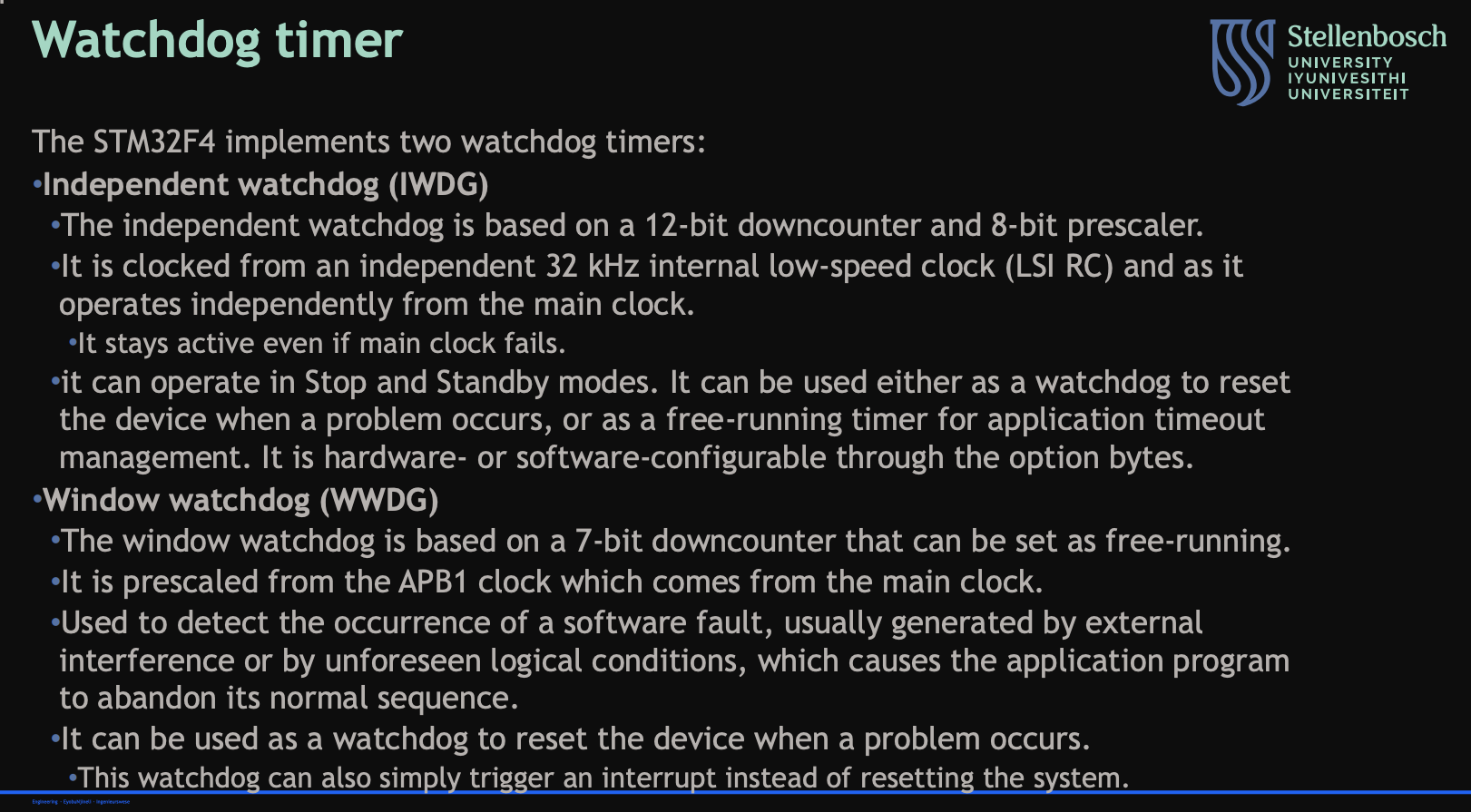
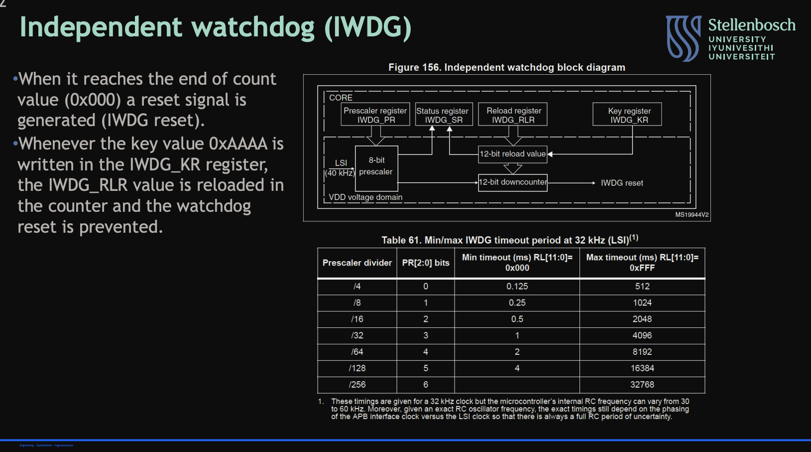
Describe the independent watchdog:
when it reaches end of count value
when a key value is written to the IWDG_KR register
Describe the real time clock:
what it is
what it does
its uses

Describe how to use the real time clock in STM32CubeIDE:
functions
use
storage
reading