Physics Chapter 12 and 13 Test
 Call Kai
 Learn
 Practice Test
 Spaced Repetition
 Match
 Flashcards
 Knowt Play
1/104

There's no tags or description
Looks like no tags are added yet.
105 Terms
What do two-dimensional images display?
SLICES of anatomy for physician interpretation
Two challenges of 2D imaging in ultrasound:
1. Sound travels in a straight line
2. Sound beam must be narrow for optimal lateral resolution
How do we overcome the challeneges of 2D imaging?
Using MULTIPLE PULSES

2-D imaging
Creating a 2-D image
• The ultrasound system sends out a pulse in a straight line (with a narrow beam width)
• The pulse returns to the machine for processing and reflections are stored.
• Another pulse is then sent out in a slightly different direction.
• These steps are repeated about 100 times in 1/100th of a second
what do we refer to scanning as ?
“real time”
Array-
A transducer assembly containing several piezoelectric elements
Phased
time delays that allow electronic steering and focusing.
mechanical steering
changing the ultrasound beam direction through mechanical means which physically points the crystal in different direction.
Mechanical Transducer
active element: Single, circular, disc shaped
• least expensive
• used by some vaginal and rectal
How is a mechanical transducer steered ?
• Mechanically steered, usually by a motor
Mechanical transducer crystals
one crystal, Resembles a coin
Mechanical transducer image shape
• Fan or sector shaped
• Greater depths= larger gaps
Mechanical transducer beam stearing
Mechanical steering (crystal rotates with a motor)
Mechanical Transducer beam focusing
• Fixed focal depth (AKA conventional, mechanical, fixed focusing)
• Internal focusing (curved active element)
• External focusing (acoustic lens)
Mechanical Transducer damages crystal
• Entire image lost
Transducer Arrays element
• More sophisticated- multiple active elements
• Slab of PZT cut into multiple separate pieces
• Each element has its own wire connecting to it allowing it to work independently of the others.
• One element or multiple elements can be excited at one time-each producing its own reflection and electronic signal.
Channel
the combination of the active element, wire, and system electronics
Linear
active elements are in a straight line
Annular
Elements are arranged as circular rings with a common center
Convex
Active elements are arranged in a bowed or arched line.
• AKA curved, curvilinear
Multidimensional
multiple elements arranged in a series of rows within the transducer
• 1.5D or 2D array

Linear Phased Arrays
Small footprint, no moving parts, focused by phasing
Linear phased array crystlals
• Number: 100-300 elements
• Shape: rectangular and narrow
• Arranged in a single row
Linear phased array image shape
Fan or sector shaped (similar to mechanical)
Linear phased array beam steering
• Electronic steering, called phasing
• Electronically transmits in different directions WITHOUT any moving parts
Linear phased array Beam Focusing
• Electronically focused
Linear phased array damaged crystal
• Inconsistent or erratic beam steering- cannot always appreciate damage when looking at image
Linear phased arrays wavelets
• Individual wavelets are created from each element → interfere and form a single beam → interfere constructively and destructively to determine beam direction and focus
How many elements are excited in phased arrays ?
ALL elements are excited in phased arrays

What do the arrows represent ?
red: electrical signals
green: PZT crystals
Linear Phased Array Beam Steering
• The electrical signals fire ten billionths of a second apart from right to left or left to right (allows the beam to steer one way or the other)
Phase delays
the name for the time difference beweeen the electrical signals of a linear phased array
If the spike line of a linear phased array has a slope
the beam is steered
if the spike of a linear phased array is in a stright line
the beam is not steered
Beam former
the electronics within the ultrasound system that create the patterns that allow steering
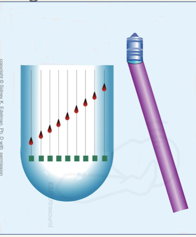
beam steering to the right : when the crystals are excited from left to right

beam steering to the left: when the crystals are excited right to left
Transmit Focusing with Linear Phased Arrays
• Creating a curved pattern with the excitation of the crystals where the outer crystals are excited first, will make a focused sound beam.

beam is unfocused : electrical spikes are alligned in a straight line

beam is focused: electrical spikes are in a curved shape

shallow focus : more severe patterns of curves
shorter time delays
• Shorter time delays= LESS curve
• Less severe curve= DEEPER focus
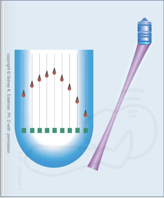
beam is being focused and steered to the left
slope
pertains to steering
curvature
pertains to transmit focusing

Multi-Focusing
accomplished by sending multiple sound beams down the same scan line
• Each of the sound beams, in a given scanline, will have a different curvature pattern of excitation, producing differing focal depths
Greatest curvature pattern in multi focusing =
shallowest focus
least curved pattern in multi focusing =
deepest focus
Dynamic Receive Focus
• Performed automatically by the system- sonographer has no control
• sound returns to the transducer- the returned sound excites neighboring elements in the probe → signals return to the ultrasound system which can be controlled by variable time delays
• Reflected sound is focused at many depths
Can focusing occur during reception ?
yes
variable time delays
change continuously throughout scanning and depend on depth of reflector.

Annular Phased Arrays
Inner rings acquire data from shallow
outer rings acquire data from deep
Annular phased array crystals
• Number: varies
• Shape: disc, multiple rings with common center (bullseye)
Annular phased arrays image shape:
• Fan or sector shaped
annular phased arrays beam steering
• Mechanical steering
Annular phased arrays beam focusing
• Multiple transmit focal zones create each scan line
• smaller diameter= shallow focus and larger diameter= deeper focus
• The image is created from the focal zone of each crystal, the rest is ignored (repeat steps for each of the rings)
Annular Phased Arrays Damaged Crystal
• When one ring of the annular array malfunctions, a portion of the image is lost in that “zone” of the image
• horizontal or side to side band of missing information.
• innermost ring will create a band in the most superficial aspect
outermost ring will create a deeper band of missing information

annular phased array damaged crystal

Linear Sequential Arrays
AKA: linear switched array
Linear sequential array Crystals:
• Number: 120-250
• Shape: Rectangular shaped strips of PZT
• Active elements are much larger than phased array
• Each crystal is about 1 wavelength in width
• Transducer face can be up to 10cm long
Linear sequential array image shape
• Rectangular
• Image is never wider than transducer face, but can be narrower
Linear Sequential Arrays beam steering
• A group of crystals fires simultaneously for each sound beam
• Beams are parallel and directed straight ahead
• A group of ten crystals will be excited and create a single sound beam, then another group of ten at slightly differing times at a different location
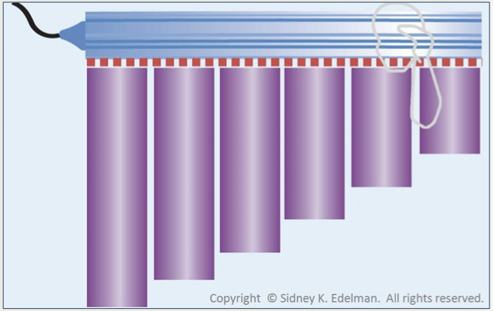
Linear sequential arrays beam focusing
• Electronically focus on transmit and receive (modern transducers).
• Transmit focus - curved excitation pattern (like linear phased array)
• This changes the near zone length and therefor changes to the focus.
• Receive focus - electrical delays in the signals returning
• Phase delays change continuously during reception, thereby focusing the beam at many depths

Linear Sequential Arrays damaged crystal
• The portion of the image extending directly below the damaged crystal will be affected.

linear sequential array damaged image
Linear sequential array element excitation
• Elements are excited in groups to allow wavelet interference to create better resolution.
• A single element firing at a time would create divergence too quickly, degrading image quality (lateral resolution)
How is electronic sound beam steering possible with linear sequential arrays ?
using sloped patterns of electrical excitation - creates a parallelogram rather than a rectangle.
Convex, Curved, Curvilinear Array Transducers
• Similar to linear arrays, but made bowed shaped to increase the clinical utility.
Convex, Curved, Curvilinear Array Transducers crystals
• 120-250
• Rectangular shaped strips of PZT
• similar in size to linear array
• 1 wavelength in width
• Transducer face can be up to 10cm long
Convex, Curved, Curvilinear Array Transducers image shape
• Blunted sector shape- convex, but does not come to a point in the near field
• Curvature at the top of the image corresponds directly to the arc of transducer face
Convex, Curved, Curvilinear Array Transducers beam steering
• Some, not all, of the crystals fire simultaneously, creating each beam.
• beams are directed straight out from the crystal
• elements are arranged in an arc, therefore the beams travel in different directions
• sound beams are not parallel
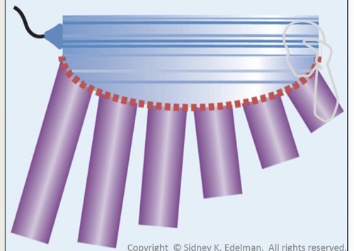
Convex, Curved, Curvilinear Array Transducers beam focusing
• Electronically transmitting and receiving (modern transducers)
• Dynamic receive focusing – varying phase delays in returning echoes
Convex, Curved, Curvilinear Array Transducers damaged crystal
• The portion of the image extending directly below the damaged crystal will be affected.
Vector, Vector Arrays or Virtual Sector
• Combo of linear sequential and linear phased array
• Sloped phase delay patterns can steer the beam in different directions
Vector, Vector Arrays or Virtual Sector crystals
• 120-250
• Rectangular shaped strips of PZT
• Small transducer face/footprint
Vector, Vector Arrays or Virtual Sector image shape
• Trapezoid shape
• At mid and deep depths, appears as sector, but the top is flat
Vector Arrays beam steering
• Some but not all of the crystals fire simultaneously, creating each beam (similar to linear sequential).
• The beams radiate out in different directions from the transducer face after excitation in a slope pattern (similar to phased array)
Vector Arrays beam focusing
• Electronically transmitting and receiving (modern transducers)
• Dynamic receive focusing
Vector Arrays Damaged Crystal
drop out

table to make things easier
yea
Slice Thickness or Elevation Resolution
• Resolution is the accuracy in imaging
• Slice thickness AKA elevation resolution also contributes to image quality and accuracy
• Is measured in a direction perpendicular to the imaging plane or above-to- below the imaging plane
What question does slice thickness or elevational resolution answer?
• Answers the question: are the reflections on the image created from structures directly in the imaging plane or from structures above or below the imaging plane?
Which arrays have the best elevational resolution ?
Mechanical and annular phased array have the best elevational resolution because they have disc shaped crystals which provide the thinnest slices.
Elevational resolution =
lateral resolution in disc shaped active elements
Getting elevational resolution
• Take a cross section of the ultrasound beam.
• thickness = height of the circle
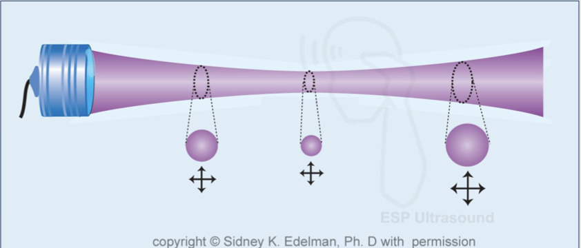
In which transducers does slice thickness not change ?
phased, linear and convex arrays
What can help reduce thickness ?
acoustic lens
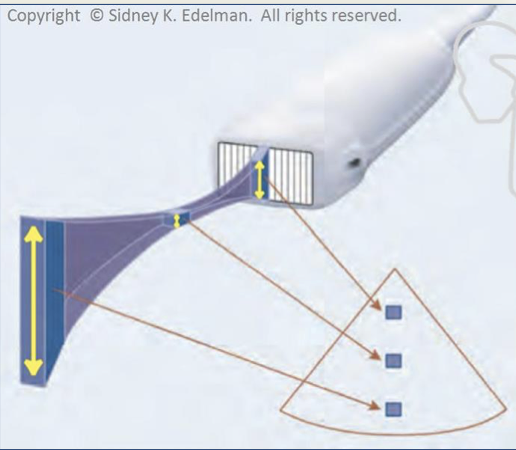
Beam thickness
• At the transducer, beam thickness = the height of the PZT
• At the focal depth, beam is at its thinnest point
• past focal depth, the beam thickens
• At all depths, the beam is thicker than it is wide

Resolution ranked (best to worst)
Phased, linear and convex arrays axial resolution
lateral resolution
elevational resolution
• 1D arrays
• Multiple elements in one dimension (lateral direction).
• Can be steered and focused electronically in only one plane (laterally)
• 1.5 D arrays
• multiple elements in the lateral dimension and (usually) three elements in the elevational dimension
•ability to steer laterally and produce two different foci in the elevational plane
What does having two different foci in the elevational plane do?
creates thinner beams with better slice thickness/elevational resolution.
• allows phasing for the vertical crystals which can thin the slices and create better elevational resolution
2 D arrays
• has multiple elements in both lateral and elevational direction.
• both electronically steered and electronically focused in two planes (lateral and elevational) such that 3D (volume) scans can be produced.
Three-dimensional imaging
• AKA volume imaging
• 2D array with thousands of crystals in a checkboard pattern
• Sound beams are electronically focused (lateral and elevational)
• Electronically steered, allowing the entire scan plan to sweep through an anatomical structure.
• 4D imaging is real time 3D
Rendering
• Constructs photo-like pictures by taking the 3D information gathered and creates color, shadows, and texture.
• post processing: can happen after the information is acquired (the patient no longer needs to be present and scanned in real time)

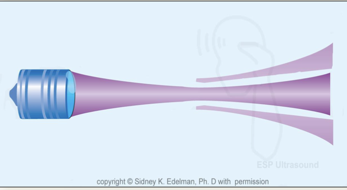
Side lobes
• Off axis sound beams created by single element transducers that causes lateral resolution to degrade
Grating lobes
• off axis sound beams created by array transducers which degrade lateral resolution, reduce image quality and create artifacts
side lobes

grating lobes