Study material
 Call Kai
 Learn
Learn Practice Test
 Spaced Repetition
 Match
Match Flashcards
 Knowt Play
1/43

There's no tags or description
Looks like no tags are added yet.
Name | Mastery | Learn | Test | Matching | Spaced | Call with Kai | Chat |
|---|
No analytics yet
Send a link to your students to track their progress
44 Terms
What does Newton’s Third Law of Motion state?
For every action, there is an equal and opposite reaction.
Explanation: A turbine engine accelerates air and exhaust rearward. The equal and opposite reaction produces forward thrust.
Source: Slides 2 and 8. Slide 2 states Newton’s Third Law, and Slide 8 applies it to turbine-engine operation. #1 Turb Eng Theory rev 1
What basic process does a gas turbine engine use to produce its high-velocity exhaust (List Each Processes)
Answer: It takes in air, compresses it, adds fuel and burns it, then directs the expanding gases rearward.
Explanation: Incoming air is compressed first. Fuel is then added and burned. Heating the compressed air causes the gases to expand, and the engine directs that high-velocity gas rearward to produce thrust.
Source: Slide 8 — Turbine Engine Theory. #1 Turb Eng Theory rev 1
What is the primary purpose of the compressor section in a turbine engine?
Answer: To compress air for combustion and supply compressed bleed air for other pneumatic needs (CHECK EXPLANATION).
Explanation: The compressor raises the pressure of the incoming air. Most of that air continues through the engine for combustion, while some compressed air can be bled off as bleed air for pneumatic uses such as cabin heat, pressurization, anti-icing, and other aircraft systems.
Source: Slide 26 — Turbine Engine Compressors: “The primary purpose of the compressor section is to compress air for combustion and for other pneumatic needs.”
Question: Besides supplying air for combustion, what other needs does the compressor section supply?
Answer: Pneumatic needs through bleed air.
Explanation: Compressed air can be bled off from the compressor and used for aircraft pneumatic systems, such as anti-icing/deicing, cabin heating, pressurization, and other pneumatic equipment.
Source: Slide 26 — Turbine Engine Compressors: “compress air for combustion and for other pneumatic needs.”
What cycle describes combustion in a turbine engine, and how does it compare with a reciprocating engine?
Answer: The Brayton Cycle, or Constant Pressure Cycle. It uses the same four basic processes as a reciprocating engine, but they occur continuously.
Explanation: Both engines use intake, compression, combustion/power, and exhaust. In a reciprocating engine, these occur as separate piston strokes. In a turbine engine, the processes occur continuously at the same time in different sections of the engine.
Source: Slide 9 — Turbine Engine Theory. #1 Turb Eng Theory rev 1
What happens to the pressure and volume of the gases during combustion in the Brayton Cycle?
Answer: Pressure remains approximately constant while the volume of the gases increases.
Explanation: The compressor has already increased the air pressure before the air enters the combustion section. When fuel burns, heat is added and the gases expand greatly. This increases their volume while combustion pressure remains approximately constant.
Source: Slides 9–10 — Brayton Cycle. Slide 9 identifies turbine combustion as the Constant Pressure Cycle, and Slide 10 shows the pressure-volume relationship. #1 Turb Eng Theory rev 1
What are the two basic types of torque-producing turbine engines?
Answer: Turboshaft and turboprop engines.
Explanation: Both engines use turbine power to produce shaft torque. A turboshaft can drive different devices, while a turboprop uses that shaft power to drive a propeller.
Source: Slide 11 — Turbine Engine Theory. #1 Turb Eng Theory rev 1
What are the two basic types of thrust-producing turbine engines?
Answer: Turbojet and turbofan engines.
Explanation: These engines primarily produce thrust by accelerating air rearward. Turbofans may be classified as low-, medium-, or high-bypass engines.
Source: Slide 12 — Turbine Engine Theory. #1 Turb Eng Theory rev 1
What does Bernoulli’s Principle state?
Answer: As fluid velocity increases, pressure decreases; as velocity decreases, pressure increases.
Explanation: This pressure-velocity relationship is used throughout the inlet, compressor, combustor, and exhaust sections of a turbine engine.
Source: Slide 14 — Turbine Engine Components. #1 Turb Eng Theory rev 1
From what viewpoint are turbine-engine locations described, and how are positions around the engine referenced?
Answer: From the pilot’s point of view, looking forward, and positions around the engine are referenced like a clock.
Explanation: Think of the circular engine face as a clock from the pilot’s viewpoint. 12 o’clock is the top, 6 o’clock is the bottom, and the other locations are described by their clock position.
Source: Slide 15 — Engine Directional Reference. #1 Turb Eng Theory rev 1

What do engine station symbols such as Pt3 and Tt7 identify?
Answer: The type of measurement and the engine station where it is taken.
Explanation: Mechanics divide the engine into stations to identify specific locations. Pt3 = total pressure at Station 3. Tt7 = total temperature at Station 7. Manufacturers may use different station-numbering systems.
Source: Slide 16 — Engine Stations. #1 Turb Eng Theory rev 1
What are the seven basic sections of a turbine engine? (List 7)
Answer:
Air inlet
Compressor section
Combustion section
Turbine section
Exhaust section
Accessory section
Systems for engine operation
Explanation:
Air inlet — brings and conditions airflow entering the engine.
Compressor — increases the pressure of the incoming air.
Combustion — mixes fuel with compressed air and burns it.
Turbine — extracts energy from the hot gases to drive the engine.
Exhaust — directs the remaining gases out of the engine.
Accessory — drives engine accessories such as pumps and generators.
Engine systems — support the systems required for engine operation.
Source: Slide 17 — Turbine Engine Components. #1 Turb Eng Theory rev 1

What is the primary purpose of a turbine-engine inlet?
Answer: To recover as much pressure from the airstream as possible and provide a uniform supply of air to the engine.
Explanation: The inlet also reduces inlet-air velocity, helps remove debris, and prepares the airflow before it reaches the compressor.
Source: Slide 18 — Turbine Engine Inlets. #1 Turb Eng Theory rev 1
Is the turbine-engine inlet considered part of the engine or the airframe?
Answer: The airframe.
Explanation: Although the inlet supplies air to the turbine engine, the inlet duct itself is considered an airframe component.
Source: Slide 18 — Turbine Engine Inlets. #1 Turb Eng Theory rev 1
What shape is a typical subsonic turbine-engine inlet, and what does it do to airflow?
Answer: It is divergent, increasing in diameter from front to back. Velocity decreases while pressure increases.
Explanation: As the air spreads through the widening inlet, it slows down and converts some of its velocity into pressure.
Source: Slide 19 — Subsonic Inlets. #1 Turb Eng Theory rev 1

What are the two types of supersonic turbine-engine inlets?
Answer: Convergent-divergent and movable-spike inlets.
Explanation: Supersonic inlets must SLOW INCOMING AIR TO SUBSONIC SPEED and convert velocity into pressure before the air enters the engine. They also have to operate throughout the aircraft’s speed range.
Source: Slide 20 — Supersonic Inlets. #1 Turb Eng Theory rev 1
[Insert picture: convergent-divergent inlet and movable-spike inlet]
Instructor note: On the ground, there is little ram-air effect because the aircraft is not moving forward. In flight, forward motion forces more air into the inlet, so the axial compressor can take greater advantage of ram air.
![<p><span style="background-color: transparent;"><strong>Answer:</strong> <strong>Convergent-divergent and movable-spike inlets.</strong></span></p><p><span style="background-color: transparent;"><strong>Explanation:</strong> Supersonic inlets must <strong>SLOW INCOMING AIR TO SUBSONIC SPEED</strong> and convert velocity into pressure before the air enters the engine. They also have to operate throughout the aircraft’s speed range.</span></p><p><span style="background-color: transparent;"><strong>Source:</strong> Slide <strong>20 — Supersonic Inlets</strong>. #1 Turb Eng Theory rev 1</span></p><p><span style="background-color: transparent;"><strong>[Insert picture: convergent-divergent inlet and movable-spike inlet]</strong></span></p><p><span style="background-color: transparent;"><strong>Instructor note:</strong> On the ground, there is <strong>little ram-air effect</strong> because the aircraft is not moving forward. In flight, forward motion forces more air into the inlet, so the axial compressor can <strong>take greater advantage of ram air</strong>.</span></p>](https://assets.knowt.com/user-attachments/dae26c74-79ab-41d3-9a79-7cb8ba8c7a13.png)
What is a bell-mouth inlet used for?
Answer: It is the most efficient inlet for a stationary engine and is also used on slow-moving aircraft such as helicopters.
Explanation: The bell-mouth shape provides smooth airflow into the engine when there is little or no forward aircraft speed.
Source: Slide 21 — Bell Mouth Inlet. #1 Turb Eng Theory rev 1

How do inertia and centrifugal separators remove debris from turbine-engine inlet air?
Answer:
Inertia separator — changes the airflow direction so heavier objects cannot follow it.
Centrifugal separator — spins the air so dirt and heavier particles are thrown out.
Explanation: Both systems use the greater inertia of heavier debris to separate it from the incoming airflow before it reaches the compressor.
Source: Slide 22 — Inertia Separation. #1 Turb Eng Theory rev 1

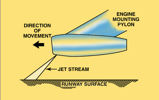
What is a vortex dissipator, and when is it activated?
Answer: A vortex dissipator directs a jet of compressed air into the area where an inlet vortex would normally form. It is activated by the air/ground (WOW) switch.
Explanation: The compressed-air jet breaks up the vortex near the inlet and helps prevent debris from being pulled into the engine while the aircraft is on the ground.
Source: Slide 23 — Vortex Dissipator. This is also directly covered in Question 8 of the Unit 1 review. #1 Turb Eng Theory rev 1 Unit 1 Review Worksheet - Rev 1
What are the two basic types of turbine-engine compressors? (List 2)
Answer:
Centrifugal-flow compressor
Axial-flow compressor — most common
Explanation: These are the two basic compressor designs used to increase the pressure of incoming air before combustion.
Source: Slide 25 — Turbine Engine Compressors. #1 Turb Eng Theory rev 1

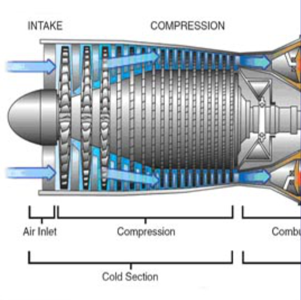
What is the primary purpose of the compressor section in a turbine engine?
Answer: To compress air for combustion and other pneumatic needs.
Explanation: As air moves through the compressor, its pressure increases. Most of that compressed air supports engine operation and combustion, while compressed or bleed air can also be used for pneumatic needs such as cabin heat and other aircraft systems.
Source: Slide 26 — Turbine Engine Compressors. The slide specifically identifies combustion and other pneumatic needs as compressor functions. #1 Turb Eng Theory rev 1
What does the diffuser do to compressor airflow in a turbine engine?
Answer: It changes velocity into pressure.
Explanation: The diffuser reduces air velocity and increases pressure. This prepares the compressed air for the combustion section.
Source: Slides 26–27 — Turbine Engine Compressors / Velocity & Pressure. This is also directly covered in Question 12 of the Unit 1 review. #1 Turb Eng Theory rev 1 Unit 1 Review Worksheet - Rev 1
What are the main characteristics of a centrifugal-flow compressor? (List 4)
Answer:
Commonly used in small turbine engines
Has a high pressure rise per stage
Can produce about a 15:1 compression ratio per stage
Does not provide enough airflow for most large turbine engines
Explanation: The centrifugal compressor creates velocity with the impeller, and the diffuser converts that velocity into pressure. Its high pressure rise per stage is an advantage, while its limited airflow makes it less suitable for large engines.
Source: Slides 27–28 — Velocity & Pressure / Centrifugal Flow Compressors. The 15:1 ratio is also directly asked in Question 13 of the Unit 1 review. #1 Turb Eng Theory rev 1 Unit 1 Review Worksheet - Rev 1

What are the main characteristics of an axial-flow compressor? (List 5)
Answer:
Airflow travels parallel to the axis of rotation
Takes advantage of ram air
Each stage consists of a rotor and stator
Rotor increases velocity; stator redirects airflow and increases pressure
Produces about a 1.25:1 compression ratio per stage
Explanation: An axial compressor builds pressure through many compressor stages. The rotor adds velocity to the air, and the stator acts as a diffuser by slowing and redirecting the air so its pressure increases before entering the next stage. On the ground, the compressor and fan pull air into the engine themselves. As the aircraft gains forward speed, ram air increases, helping force more air into the inlet and allowing the axial compressor to take greater advantage of the incoming airflow.
Source: Slide 30 — Axial Flow Compressors. The 1.25:1 ratio and rotor/stator stage are also directly covered by the Unit 1 review. #1 Turb Eng Theory rev 1 Unit 1 Review Worksheet - Rev 1 Unit 1 Review Worksheet - Rev 1

Question: What are the three designs used to attach compressor blades to the compressor disc? (List 3)
Answer:
Bulb
Fir-tree
Dovetail
Explanation: These are the blade-root attachment designs that fit the compressor blade into the disc. They are different from the locking methods used to hold the blades in position.

Question: How can compressor blades be locked or held in position after they are attached to the disc? (List 3)
Answer:
Pins
Lock tabs
Lock wire
Explanation: These prevent the compressor blades from moving out of position after they have been installed in their blade-root attachment.
Question: What can cause compressor blade vibration, and what can help reduce it?
Answer: Overlapping mid-span shrouds or blades being out of position can cause vibration. Fan lubricant can help reduce it.
Explanation: Compressor/fan blades must remain correctly positioned. The PowerPoint specifically notes that molybdenum disulfide lubricant may be used to help eliminate fan-blade vibration.
Question: What is a compressor blisk?
Answer: A one-piece compressor blade and disc assembly.
Explanation: Instead of separate blades being attached to a disc, the blades and disc are manufactured as one piece. Blisks can also be used in turbine sections.

Question: Why are axial compressor blades twisted, with a higher stagger angle at the tip than at the root?
Answer: To maintain consistent airflow velocity along the length of the blade.
Explanation: The blade tip travels faster than the root because it covers a greater distance during each revolution. The changing stagger angle compensates for this difference and helps maintain consistent airflow along the blade.
Source: Slide 34 — Compressor Blades. #1 Turb Eng Theory rev 1

Question: What is the purpose of a mid-span shroud on a compressor/fan blade?
Answer: To support the blade against bending forces.
Explanation: The mid-span shroud provides support to the first-stage fan blades and helps control blade movement. Newer composite blades may not require these shrouds.
Source: Slide 34 — Compressor Blades.
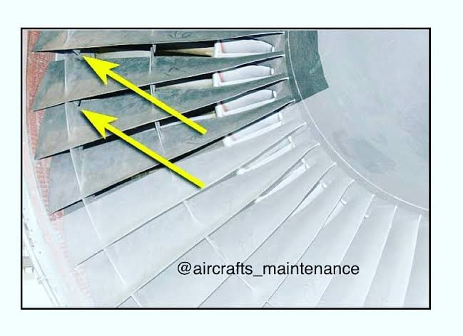
Question: What is the difference between a square-tip compressor blade and a profile-tip (squealer-tip) compressor blade?
Answer:
Square tip — thicker blade tip and more prone to vibration/resonance and damage if it rubs the case.
Profile/squealer tip — has a thinner, reduced tip designed to reduce vibration and blade-tip damage.
Explanation: The profile tip changes the blade’s natural vibration frequency so it stays outside the engine’s normal vibration range. Its shape also creates a vortex that increases air velocity near the tip and reduces tip leakage.
Source: Slide 35 — Compressor Blades, plus the Gleim compressor-blade material.

Question: What is the purpose of an abradable compressor shroud?
Answer: To keep blade-tip clearance as small as possible.
Explanation: The compressor blades can lightly wear into the abradable shroud. This creates a close fit between the blade tips and the case and helps limit airflow leakage.
Source: Slide 36 — Compressor Blades. #1 Turb Eng Theory rev 1

Question: What are the functions of the inlet guide vanes and outlet vane assembly in a turbine-engine compressor?
Answer:
Inlet guide vanes — direct air into the first compressor stage in the direction of rotation and support the front bearing.
Outlet vane assembly — straightens the airflow and directs it into the diffuser.
Explanation: These stationary vanes help control the direction of airflow entering and leaving the compressor.
Source: Slide 37 — Inlet Guide Vanes / Outlet Vane Assembly.

Question: What do stator vanes do in an axial-flow compressor?
Answer: They decrease air velocity, increase pressure, and direct the airflow at the proper angle for the next rotor stage.
Explanation: Compressor stators form divergent passages. As the air slows, its pressure rises. The stators also redirect the airflow so it enters the next rotor blades at the correct angle.
Source: Slide 38 — Turbine Engine Compressors. Gleim also tests these stator functions directly.

Question: What is the purpose of variable stator vanes in a turbine-engine compressor?
Answer: To control the angle at which airflow contacts the next stage of compressor blades.
Explanation: The vanes change position as engine operating conditions change so the airflow reaches the next compressor stage at the proper angle. They are controlled by the EEC. The final stator stage, called the exit guide vanes, returns the airflow to an axial direction.
Source: Slides 39–40 — Stator Vanes / CF6 Stator Vane Control. Slide 40 uses the CF6 as an example of how variable stator vanes can be actuated.

Question: What are the two types of compressor stall?
Answer:
Rotational stall
Axi-symmetric stall, or compressor surge
Explanation:
Rotational stall: A small/localized disruption of airflow develops in part of the compressor and rotates around the compressor instead of moving normally through it. The entire compressor has not lost compression.
Axi-symmetric stall / compressor surge: A much more severe condition where there is a complete breakdown of compression across the compressor. This can cause the airflow to reverse direction through the compressor.
Source: Slide 42 — Compressor Stalls.
Question: What causes a compressor blade to stall?
Answer: The blade’s critical angle of attack is exceeded.
Explanation:
Cause: Compressor blades are airfoils. Their angle of attack is affected by compressor RPM and inlet-air velocity. If the airflow meets the blade at too high an angle, the blade stalls.
How it is controlled: Variable guide/stator vanes and compressor bleed valves help maintain the proper airflow and angle of attack. Variable vanes adjust the direction/velocity of the airflow, while bleed valves relieve compressor pressure during conditions such as low RPM.
Source: Slide 44 — Compressor Stalls.
Question: What determines the relative wind and proper angle of attack in a turbine-engine compressor?
Answer: Compressor RPM and airflow velocity.
Explanation: As compressor RPM increases, the airflow must also move faster to maintain the proper angle of attack. Higher RPM requires higher airflow velocity.
Source: Slide 45 — Compressor Stalls. #1 Turb Eng Theory rev 1
Question: How do variable stator vanes change between idle and high power to help prevent compressor stalls?
Answer:
Idle/low power: vanes close to slow the airflow
High power: vanes open to increase airflow velocity
Explanation: Variable stator vanes adjust airflow velocity to match compressor RPM. This helps keep the airflow at the proper angle of attack as engine speed changes.
Source: Slide 46 — Variable Stator Vanes.
Question: How do compressor anti-stall bleed valves help prevent compressor stalls?
Answer: They relieve compressor air pressure at low power and low RPM to maintain proper airflow velocity.
Explanation: At low RPM, the compressor may not move enough air efficiently. Opening the bleed valves lets some air escape, helping maintain airflow through the compressor and preventing an excessive angle of attack. They are commonly open during starting and low-RPM operation.
Source: Slide 47 — Compressor Anti-Stall Bleed Valves. #1 Turb Eng Theory rev 1
Question: What are the main benefits of a multi-spool compressor? (List 3)
Answer:
Quick acceleration
Better control of compressor stalls
Each spool can respond independently to changes in air density or flight conditions
Explanation: The N1 and N2 spools can operate at different speeds instead of being locked together. This allows each compressor section to operate closer to its best RPM for the current conditions. The core spool is controlled by the fuel control.
Source: Slides 48–49 — Multi-Spool Compressors.

Question: Where is the diffuser section located in a turbine engine?
Answer: Between the compressor and the burner/combustion section.
Explanation: The diffuser reduces air velocity and increases pressure before the air enters the combustor. Slower, higher-pressure air provides better conditions for combustion.
Source: Slide 50 — Diffuser.