ASCI 356 Exam 2
 Call Kai
 Learn
 Practice Test
 Spaced Repetition
 Match
 Flashcards
 Knowt Play
1/86

There's no tags or description
Looks like no tags are added yet.
87 Terms
primary flight controls
ailerons, elevator (stabilizer), and rudder are required to control and aircraft safely during flight
secondary flight controls
wing flaps, leading edge devices, spoilers, and trim systems that improve the performance characteristics of the airplane or relieve the pilot of excessive control forces.
ailerons
control roll about the longitudinal axis, attached to the outboard trailing edge of each wing and moves in opposite directions of each other
frise-type ailerons
aileron pivots on an offset hinge, projecting the leading edge of the aileron into the airflow to help reduce adverse yaw
differential ailerons
can put each aileron in different positions
coupled ailerons and rudder
linked controls, automatically deflects rudder when airlerons are deflected to correct adverse yaw
types of flight controls: mechanical
direct linkage systems that use physical components—such as steel cables, push-pull rods, pulleys, bellcranks, and chains
simple and reliable, but does not evolve well
types of flight control: hydromechanical
combines physical mechanical linkages with hydraulic power systems to move an aircraft's control surfaces
has gust lock, can evolve, more expensive
types of flight control: fly-by-wire
replaces physical connection between pilot controls and flight control surfaces with an electrical interface
more reliable, more expensive
gust lock
a mechanical or physical device used to secure an aircraft's control surfaces (ailerons, elevators, and rudder) and controls when parked on the ground
horizontal stabilizer
small, wing-like surface located on the tail (empennage) of an aircraft that keeps the plane balanced and prevents unwanted up-and-down movement of the nose, known as pitch
C-172 flight controls
primary: elevator, ailerons, rudder, brakes
secondary: flaps, trim system
MCAS 737 Max
implemented to compensate for placing engines forward & up
Artificial feel unit (AFU)
provide feedback (as resistance) to mimic mechanical flight controls
Why do pilots need artificial feel units (AFU)
With hydraulic, and fly-by-wire systems, pilots don’t get “real” feedback like mechanical systems. Lack of ‘feel’ can cause oversteering and other problems
rudder bias system
pushes rudder towards the good engine to help decrease yaw excursion in the event of an engine failure
yaw damper
improves stability by damping out oscillations in yaw
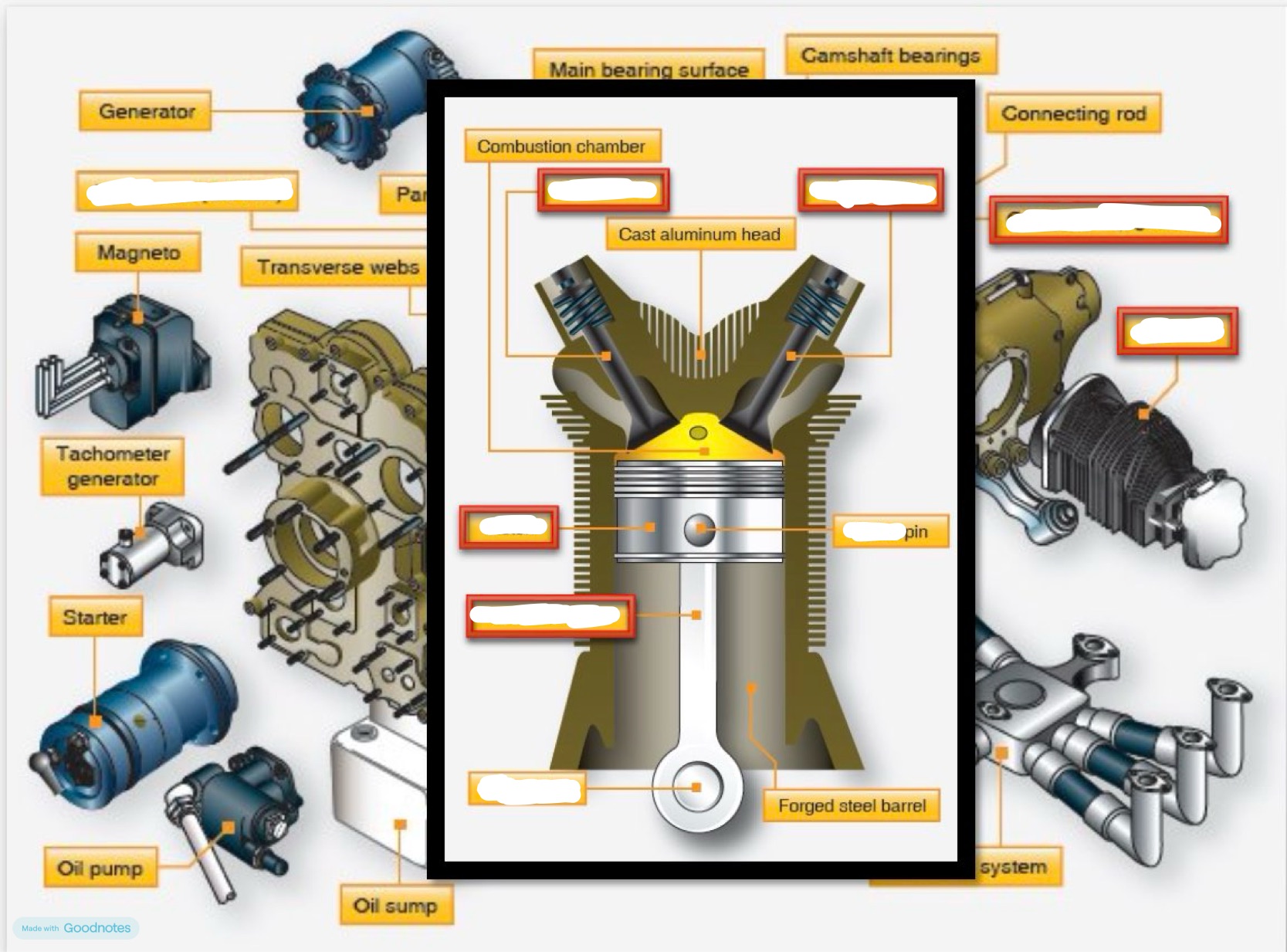
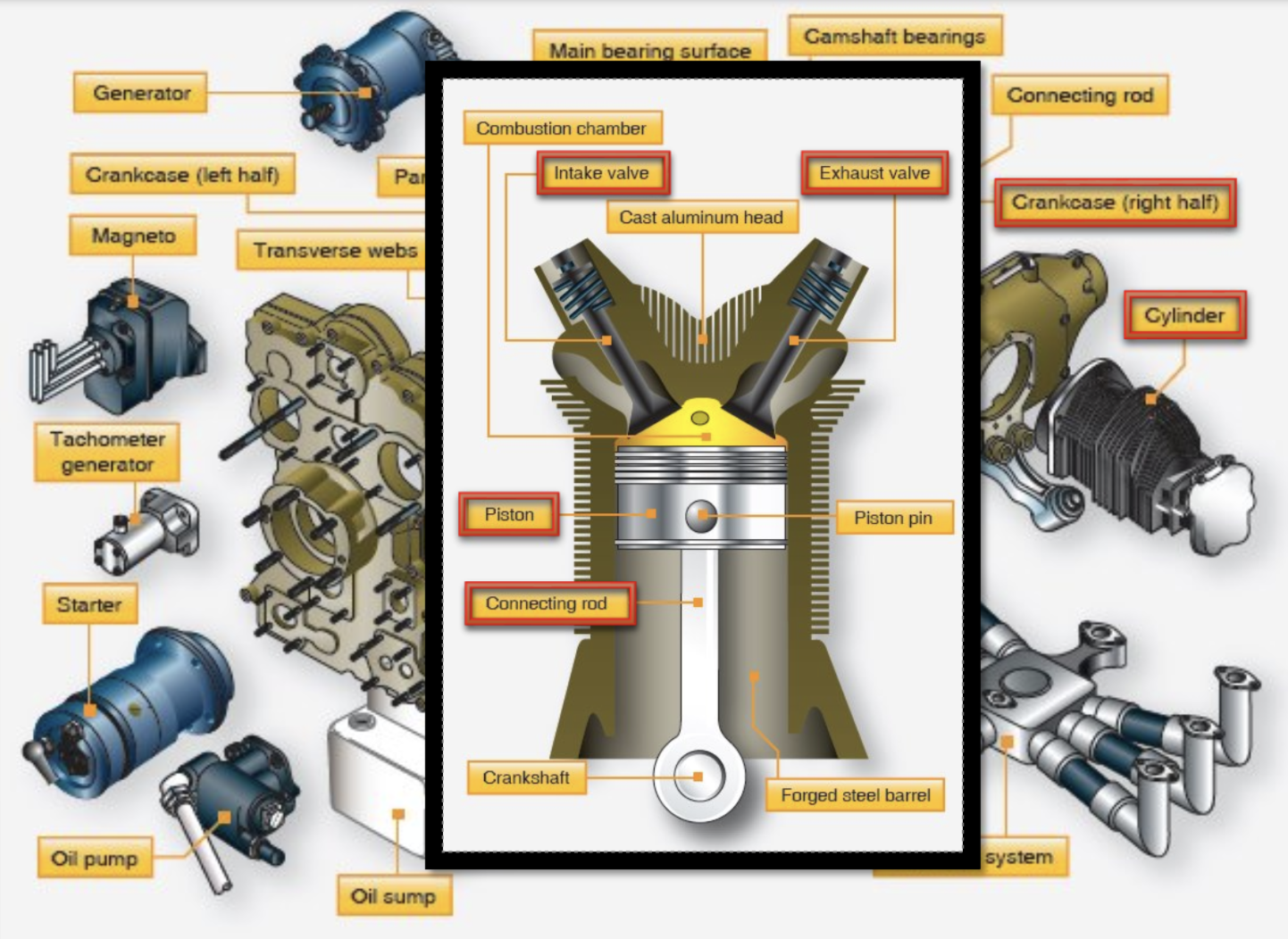
parts of reciprocating engine
“crankshaft turns the propeller”
4 stroke cycle engine: intake stroke
(STEP 1) piston is pulled downward by the rotation of the crankshaft, increases the volume inside the cylinder, and causing air to flow through the carburetor (SUCK)
4 stroke cycle engine: compression
(STEP 2) As piston approaches TDC after being loaded, the fuel/air mixture is compressed and is fired by an electric shock (SQUEEZE)
4 stroke cycle engine: power
(STEP 3) piston is forced downward by the pressure of the burning gasses being exerted on it, downward movement of the connecting rod is changed to rotary movement by the crankshaft. This movement is then transmitted to the propeller shaft to drive the propeller (BANG)
4 stroke engine power: exhaust
(STEP 4) pushes the burned exhaust gases out of the exhaust port as it travel to the bottom dead center (BLOW)
turbo/super chargers: why do we need them?
the fuel air mixture flowing into an aircraft engine must be relatively consistent, making a better mixture for the plane to consume
lower air pressure higher up
turbosuperchargers
externally driven superchargers derive power from energy of engine exhaust gases directed against a turbine that drives an impeller that compresses incoming air (COMPRESSED BEFORE F/A MIXTURE)
superchargers (internally driven)
compress f/a mixture after it leaves the carburetor by using a compressor powered by the crankshaft
gasoline vs diesel engine
has the highest effective efficiency
can combust many different (cheaper) fuels
very good exhaust-emmision behavior
no high voltage system (great reliability and easy adaptation to damp environments)(no radio interference)
can accept super or turbo charging pressure with no limits
C-172 IO-360: Engine
direct drive, horizontally opposed, 4-cylinder, overhead valve, air cooled, fuel injected engine with a wet sump lubrication system
C-172 IO-360: Fuel Lubrication System
Oil is drawn from the sump through a filter screen on the end of a pickup tube to the engine driven oil pump. Oil from the pump passes through a fuel-flow filter, with a pressure relief valve and a thermo controlled oil cooler. Oil from the remote cooler is then circulated to the left oil gallery. The engine parts are lubrictated by oil from the galleries. After lubricating the engine, the oil returns to the sump by gravity.
C-172 IO-360: Ignition and Starter System
Ignition is provided by two engine driven magnetos, and two spark plugs in each cylinder.
C-172 IO-360: Air Induction System
receives ram air through an intake covered by an air filter to remove dust and other matter in the air. Airflow then enters an air box, equipped with a spring-loaded alternate air door. If filter becomes blocked, suction will open the door and draw unfiltered air. This will result in a 10% power loss at full throttle. After passing through box, air enters the fuel.air control unit and is ducted into the cylinders.
C-172 IO-360: Fuel Injection System
After reaching the cylinders, fuel manifold evenly distributes the fuel to an air-bleed type injector nozzle in the intake valve chamber of each cylinder. A transducer between the f/a control unit and fuel distribution unit sends digital signals that display fuel flow in the cockpit.
C-172 IO-360: Cooling System
Ram air in for engine cooling
DA-42: Austro E4-C Engine
Liquid Cooled, four cylinder, four stroke, with wet sump lubrication
digital engine control with integrated propeller governor
turbo charger with intercooler
Each engine can only be operated with the ENGINE MASTER switch ON. Each engine has its own ECU.
Each ECU controls their respective engine’s manifold pressure, injected fuel quantity and propeller speed
DA-42: Austro E4-C Alternate Air Lever
In the event of a power loss because of icing/blocking of the air filter, there is a way to draw air from the engine compartment. This lever serves both engines simultaneously to help air flow.
Problems needed to be solved for battery powered aircraft
Everyday LI-ION batteries still only have 1/43 the energy density of everyday airplane fuel
doubling the mass of the aircraft increases the power requirement 8 times
Smaller recips are starting to become a thing but, are not equal alternatives yet
Need batteries with much higher energy density
hydrogen fuel cells
hydrogen and oxygen are used like positive and negatively charged halves of a battery
movement of electrons generates current
problems:
hydrogen is 5x as expensive
process of making pollutes
still takes more energy to make than we yield
storing and transport require even more energy (must be super-cooled)
power density still too low
hydrogen combustion
alternative to jet fuel combustion
lower pressure ratio engines (more reactive)
hydrogen combustion problems
H2 availability at airports and refueling
danger with engines (can not detect leaks)
storage
fixed-pitch propellers
designed for best efficiency at one rotational and forward speed
anything other than that speed is an efficiency decrease
constant-speed propeller
pilots sets a propeller speed
Prop governor maintains that set speed

parts of propeller

propeller governers
governer maintains the set speed by pilot
increase ro decrase blade pitch control
increase pitch = decrease RPM
DA-42 Prop
constant speed, hydraulically regulated.feathering
ECU sets pitch via the governer
adding oil pressure decreases the pitch
if feathered, oil flows back from the hub
Propeller Efficiency
the ratio of Thrust HP : Shaft HP
geometric pitch - effective pitch = slip
Propeller (Shaft HP)
comes from the engine
Thrust HP
Comes from the propeller
forces acting on a propeller: centrifugal force
physical force throws prop away from hub (most dominate)
detonation
an explosion, or the uncontrolled burning of the fuel air mixture inside the cylinder of a reciprocating engine
fuel system terms
REFER TO: briefing 19, slide 8
Fuel ALWAYS goes back to reservoir
AVGAS vs Jet fuel
AVGAS:
less viscous
more volatile
more flammable
lower flash point
Jet fuel:
all opposite
fuel lines/fittings
can be rigid/flexible
rigid: aluminum alloy/ stainless steel
flexible: rubber interior, then braided, then covered
metal ones need to be grounded

fuel pump construction
engine driven pump, mechanically driven

Types of fuel pumps: Piston Pump (Primer)
injects a fine mist or squirt of fuel directly into the engine cylinders
centrifugal boost pump: a heavy-duty rotary machine that converts motor mechanical energy into fluid pressure using a rotating impeller
pulsating electric pump: smaller, less expensive axillary
vane type pump: constant displacement pump that moves a constant volume of fuel. Can be engine driven or axillary
aux/boost pump
CESSNA:
fuel return system keeps temps lower on hot days
can support max continuous power
primary use: priming engine
secondary use: vapor suppression
continuous use enriches mixture
IN GENERAL:
primary purpose is to deliver fuel to engine pump inlet (priming engine)
secondary purpose is back during:
start
takeoff
high altitude
engine driven pump
primary fuel delivery device that can deliver fuel under pressure to the fuel metering device
Fuel Flow Meters
many types
simplest is pressure gauge
modern W(f) transducer typically are installed downstream of the last fuel pump using a laser
Capacitance Type Fuel Sensing/Indicating
two concrete plates at a fixed distance and the capacitor measures the material between them. Translates fuel quantity into pounds. Compensator unit accounts for fuel temperature changes.
Fuel Filtration
Filter: fine mesh that can trap contaminates on the micron level
strainer: relatively coarse wire mesh fuel flows through by the help of gravity
typically multiple:
fuel tank
between tank and inlet to engine driven pump
between engine driven pump and fuel metering device
Fuel Indicating
IN GENERAL:
electronic quantity indicating is most common
gauge face does not matter
convert variable resistance into a digital signal to be processed by the computer
CESSNA:
1 fuel quantity sensor in each wing tank
0 gals indicated, means 1.5 gals (unusable) remain
sensor management range is 24 gal
“low level” at 5 gal
not accurate in slips/skids
indicator will flash red at 0 gal
fuel flow indicates:
turbine type transducer
located between FCU and flow divider
fuel vent system (C172)
complete blockage of the fuel vent system will result in decreasing fuel flow and eventually engine stoppage
selector valve: operate in “left”, “right”, or “both” for fuel flow to the engines
when ¼ tank or less, prolonged uncoordinated flight may result in fuel tank outlets being uncovered and start to starve the engine
fixed v retractable gear pros/cons
retractable:
eliminates the added drag penalty from fixed landing gear
used only when the drag is higher than the weight penalty (drag>weight penalty)
fixed:
avoids the added weight penalty that is not worth it in smaller GA aircraft
shock absorbing landing gear
transfer shock energy from landing on the ground and distributes it throughout the airframe
can be converted into heat
shock struts
most common method of shock dissipation
uses compressed air & hydraulic fluid
compression forces fluid to be passed through a small orifice to the top of the strut
building pressure and the passage of the fluid through the orifice causes heat
this pressure creates the resistance needed when landing a heavy piece of machinery which causes the aircraft to begin moving upward farther from the ground after landing
large aircraft landing system
most commonly use a hydraulic pump from the accessory drive
all small gear components and:
door actuators: opening and closing the doors of the landing gear bay during takeoff and landing sequences
sequencing valves: valve that ensures landing gear components (such as the gear legs and wheel well doors) deploy or retract in a strict, predetermined order
uplocks / downlocks: mechanical safety and securing mechanisms used in an aircraft's retractable landing gear system to hold the wheels safely in place during flight and upon landing
almost always has a backup electrical hydraulic pump
Small airplane landing gear systems
self-contained, electrically driven (reversable) hydraulic pump that pressurizes fluid to raise and lower the landing gear
landing gear safety (squat) switch
switch positioned to open and close depending on the extension or compression of the main landing gear strut
wired into any number of system operating circuits
circuit prevents gear from being retracted while the aircraft is on the ground, creating a “lock-out”
aircraft wheels (material)
two-piece rims to prevent tire stretching
made out of forged aluminum or alloy halves
sealed o-ring at mating surface
aircraft wheels (construction)
inboard wheel half has to host brakes
inner half often hosts the thermal and overinflation plugs (melt if wheels/brakes are too hot to avoid and explosion by deflating the tires)
outer half often hosts the wheels speed transducer:
DA-42 Retractable Gear
hydraulic pressure via electric pump
hydraulic pressure keeps the gear in the retracted positon
warning horn with less than 20 % power on aircraft
squat switch prevents unwanted gear retraction
emergency gear extension releases the pressure holding the gear in the retracted position
forces acting on a propeller: Torque bending force
bends prop in opposite direction of rotation
forces acting on a propeller: Thrust bending force
bends the prop blades forward
forces acting on a propeller: Aerodynamic twisting force
turns blades to high blade angle
forces acting on a propeller: centrifugal twisting force
forces blades towards a low blade angle
Types of fuel pumps: Centrifugal boost pump
a heavy-duty rotary machine that converts motor mechanical energy into fluid pressure using a rotating impeller
Types of fuel pumps: Piston Pulsating electric pump
smaller, less expensive axillary
Types of fuel pumps: Vane type pump
constant displacement pump that moves a constant volume of fuel. Can be engine driven or axillary
brakes
Converts the kinetic energy of aircraft in motion to heat energy through the creation of friction.
common aircraft brake designs
independant of hydraulic system (non-hydraulic)
hydraulic system boost (light aircraft)
Hydraulic System Powered (airliners)
large aircraft brake system
segmented rotor-disk brakes are multiple disc breaks. a disk rotates with the turning wheel assembly, along with a sttionary caliper. When pressure is applied by the hydraulic system, this caliper resists the rotation of the wheels.

large aircraft brake system components

carbon brakes
carbon fiber materials
40 percent lighter
newer, more advanced
withstand higher temps
dissipate heat faster
longer service life
expensive
anti skid system (how it works)
detects imminent skid by seeing how fast the wheel is turning compared to how fast it SHOULD be turning
all wheels should be turning the same speed, if not a skid is occurring
modulates break pressure
anti-skid components: wheel sensor
built like a transducer
RPMs is produced by the wheel speed
output is fed to control unit
anti-skid components: control unit
the brain of the system
looks for changes in voltage/wheel speed
compares aircraft speed to wheel speed
compares wheels sped to other wheels
anti-skid components: control valve
fast-acting, electronically controlled hydraulic valve
adjusts pressure to the brakes
Skid v anti-skid performance
skid:
longer stopping distances
high risk of flat tire/blowout
carefully pump brakes
C-172 Brakes
single disc brake on each MLG
pilot (only) has set of master cylinders attached
parking brake sets both wheels
minimize brake usage during taxi and landings