APU (Auxilary Power Units)
 Call Kai
 Learn
Learn Practice Test
 Spaced Repetition
 Match
Match Flashcards
 Knowt Play
1/15

There's no tags or description
Looks like no tags are added yet.
Name | Mastery | Learn | Test | Matching | Spaced | Call with Kai | Chat |
|---|
No analytics yet
Send a link to your students to track their progress
16 Terms
Question: What are the two main functions of an Auxiliary Power Unit (APU)?
Answer:
Pneumatic power
Electrical power
Explanation:
Pneumatic power: Normally places the greatest demand on the APU. Pneumatic power is used for things such as:
Main engine starting
Cabin air conditioning
Electrical power: Supplies electricity to operate aircraft systems before the main engines are started and can also provide backup electrical power during an emergency.
Source: Slide 2 — APU Functions. #3 Auxiliary Power Units
Question: What are the operating capabilities of the 767-400 APU?
Answer:
Produces 120 KVA of electrical power at any operating altitude
Supplies pneumatic power up to 17,000 feet
Explanation: The 767-400 uses an Allied Signal GTCP 331-400B APU. Its electrical generator can continue supplying rated electrical power throughout its operating-altitude range, while its pneumatic capability is altitude-limited.
Source: Slide 3 — 767-400 APU. #3 Auxiliary Power Units
Question: What is a typical APU installation, and what fire-protection features are used?
Answer:
The APU is installed inside a fire-resistant shroud
APU fires are extinguished using Halon bottles
Fire bottles are located forward of the APU bulkhead
The APU inlet is located above the right-hand horizontal stabilizer on the installation shown
Explanation: The fire-resistant shroud helps contain and isolate an APU fire. If a fire occurs, the Halon fire-extinguishing system can discharge into the APU compartment.
Source: Slide 4 — Typical APU Installation.

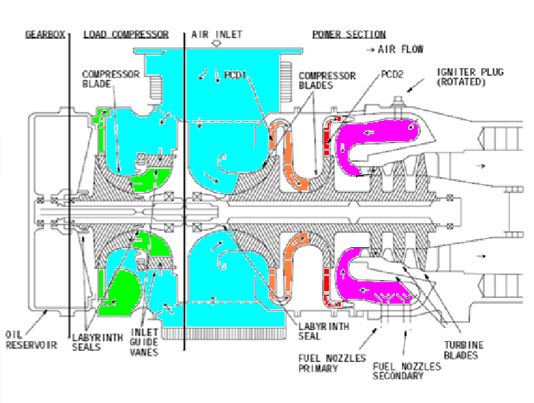
Question: What are the three major parts shown in a typical APU turbine engine, and what does each do?
Answer:
Power section — produces the mechanical power needed to operate the APU.
Load compressor — produces compressed pneumatic air.
Gearbox — drives the APU accessories.
Explanation:
Power section: Uses a single-shaft turbine. That single shaft drives both the load compressor and gearbox.
Load compressor: A centrifugal compressor that supplies the APU's pneumatic output. Inlet guide vanes (IGVs) control how much air flows through it.
Gearbox: Contains gears and mounting pads for accessories, such as the electrical generator.
Source: Slide 5 — Typical Turbine Engine.
Question: Why must an APU be self-monitoring, and what does the ECU do?
Answer: Because the APU must be able to operate without a person constantly monitoring it.
Explanation:
The ECU — Electronic Control Unit monitors APU operating conditions, including:
EGT
Load-compressor airflow
Other engine operating conditions
If the ECU detects a discrepancy that requires protection, it will command an automatic shutdown.
The ECU also stores a fault message so maintenance personnel can retrieve it later using BITE — Built-In Test Equipment.
Source: Slide 6 — APU Self-Monitoring. #3 Auxiliary Power Units
Question: What lubrication-system conditions automatically shut down the APU, and which conditions create a locked BITE message?
Answer:
Automatic shutdown:
Low oil pressure
High oil temperature
Locked BITE message:
Low-oil-pressure switch fault
Lube bypass
High-oil-temperature sensor fault
Generator-filter differential-pressure switch fault
Explanation:
Automatic shutdown: Low oil pressure or excessive oil temperature can directly threaten the APU, so the system shuts the APU down automatically.
Locked BITE message: A BITE — Built-In Test Equipment — message is stored in the system's memory so maintenance personnel can retrieve the fault later. It gives mechanics a record of the detected problem even after the event has passed.
Source: Slide 8 — APU Lubrication System.
Question: Where does the APU receive its fuel, and how can it receive fuel without AC electrical power?
Answer: APU fuel comes from the main aircraft fuel tanks, and a DC fuel pump can supply fuel when AC power is unavailable.
Explanation: This allows the APU to receive fuel and be started before the aircraft's normal AC electrical system is operating.
Source: Slide 9 — Fuel Supply. #3 Auxiliary Power Units
Question: What is the basic sequence for starting an APU?
Answer:
Battery switch ON
Move the APU start switch to START, then release it to ON
Start panel opens the inlet door
Start panel energizes the ECU (Electronic Control Unit)
ECU controls the remainder of the start
Explanation: On most aircraft, the APU is initially started from the main aircraft battery. Once the inlet door is opened and the Electronic Control Unit (ECU) is energized, the ECU automatically manages the rest of the APU start sequence.
Source: Slide 10 — Starting the APU. #3 Auxiliary Power Units
Question: What two operating speeds does the 767-400 APU use, and when are they used?
Answer:
100% — 39,850 RPM: normal operating conditions
101% — 40,400 RPM: during main engine starting
Explanation: During a main-engine start, the APU increases slightly to 101% RPM because the pneumatic starting load places a greater demand on it.
Above 36,000 feet, the APU is allowed more time to reach operating speed because the atmosphere is thinner.
The ECU automatically controls these functions.
Source: Slide 11 — 767-400 APU Operating Speed.
Question: How does an APU provide “Electrical Power” to the aircraft?
Answer:
Most aircraft APUs use the same type of generator installed on the main engines.
At 100% APU RPM, the accessory gearbox drives the generator at the proper speed to produce the required electrical power.
Explanation: The APU itself provides the mechanical rotation. The accessory gearbox transfers that rotation to the generator.
When the APU is operating at 100% rated speed, the generator is driven at the speed needed to provide the aircraft with the proper electrical output.
The PowerPoint refers to the generator attachment location as the gearbox mounting pad, but the important point for this slide is:
APU at 100% RPM → generator driven at proper speed → electrical power supplied to the aircraft.
Source: Slide 12 — Electrical Power.
Question: How does an APU maintain engine speed while supplying “Pneumatic Power”, and what happens if maximum EGT is reached?
Answer:
The APU runs at its rated speed at all times.
As pneumatic load increases, the APU fuel control increases fuel flow to maintain engine speed.
If the APU reaches maximum EGT, the load control valve closes to reduce the pneumatic load and prevent an overtemperature. (Exhaust Gas Temperature)
Explanation: More pneumatic demand puts a greater load on the APU. The fuel control adds fuel so the APU can maintain its rated RPM.
If the load becomes too great and the APU reaches its maximum EGT, the system protects the APU by reducing the pneumatic load through the load control valve.
Source: Slide 13 — “Pneumatic Power”. #3 Auxiliary Power Units
Question: How does the 767-400 APU control “Pneumatic Power” efficiently?
Answer: The ECU (Electronic Control Unit) controls the inlet guide vanes (IGVs) according to pneumatic demand.
Explanation: The IGVs control how much air flows through the load compressor.
More pneumatic demand → IGVs allow more airflow.
Less pneumatic demand → IGVs reduce airflow.
This improves efficiency because the APU is only pressurizing the volume of air that is needed.
Source: Slide 14 — “Pneumatic Power”. #3 Auxiliary Power Units

Question: What does the surge control valve do during APU “Pneumatic Power” operation?
Answer: The surge control valve protects the load compressor from reverse airflow.
Explanation: The surge control valve is:
Open during startup and shutdown
Used to unload the compressor
The unloaded air is sent out through the APU exhaust
Opening the valve during startup and shutdown helps prevent the load compressor from going into surge/reverse flow.
The airflow picture is:
Air enters the APU load compressor → compressor squeezes it → compressed air leaves the compressor and goes into the pneumatic ducting.
During startup/shutdown, the compressor is spinning slower, so it cannot keep pushing that compressed air forward as strongly.
The pressure that “pushes back” is simply the compressed air already sitting on the outlet side of the compressor. If the compressor can’t keep overcoming that pressure, the airflow can stall and briefly move backward — that is surge.
So the surge valve opens and gives that compressed air an easier exit:
Compressor → surge valve → APU exhaust
That lowers outlet pressure so the air keeps flowing forward through the compressor. The PowerPoint specifically says the surge valve opens during startup/shutdown, unloads the compressor, and sends the air to the exhaust.
Source: Slide 15 — “Pneumatic Power”.

Question: What should be done before “APU Shutdown”, and why?
Answer:
Turn all pneumatic bleed valves OFF
Allow the APU to run unloaded for at least 2 minutes
Explanation: All APUs should have a cooldown period before shutdown.
Allowing the APU to run unloaded lets the hot section cool gradually. Shutting it down without the cooldown period can shock-cool the engine and reduce hot-section life.
Source: Slide 16 — “APU Shutdown”.
Question: What happens during a normal 767-400 “APU Shutdown”?
Answer:
Turn the APU control switch OFF
Pneumatic and electrical loads are automatically removed
APU speed decreases to 85%
APU cools for 2 minutes
Overspeed test signal is input and the fuel solenoid closes
At 15%, the inlet door and fuel valve close
Explanation: Most of the shutdown sequence happens automatically after the APU control switch is moved to OFF.
Important exception: During an APU fire or automatic shutdown, the APU shuts off immediately rather than going through the normal cooldown sequence.
Source: Slide 17 — “APU Shutdown”.