Earthing and Protection
 Call Kai
 Learn
 Practice Test
 Spaced Repetition
 Match
 Flashcards
 Knowt Play
1/40

Earn XP
Description and Tags
Essential vocabulary flashcards covering shock protection, earthing arrangements, equipotential bonding, extra-low voltage systems, protective devices, testing procedures, and special installation locations.
41 Terms
EEBADS
An older teaching acronym for "Earthed Equipotential Bonding and Automatic Disconnection of Supply," an overarching shock protection method now commonly referred to as Automatic Disconnection of Supply (ADS).
Direct Contact
The act of a person or livestock touching an electrical installation part that is normally live under healthy working conditions (governed by basic protection).
Indirect Contact
The act of a person or livestock touching a conductive part of an electrical installation that is not normally live, but has become live due to an insulation failure or fault (governed by fault protection).
Main Earthing Terminal (MET)
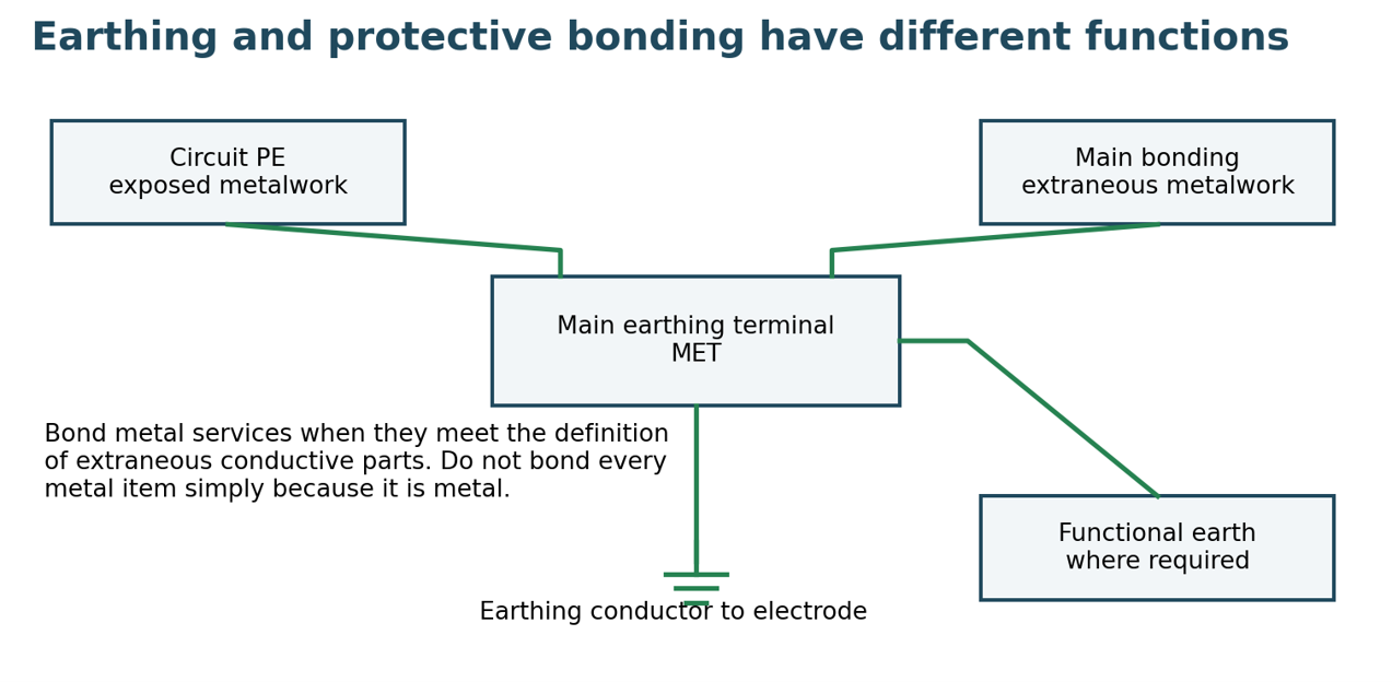
A dedicated terminal or bar provided in an installation to connect together protective bonding conductors, earthing conductors, circuit protective conductors (PE), and functional earthing conductors.

Earth Electrode
A metallic conductor—such as a driven copper or galvanized-steel rod, embedded plate, or tape lattice—placed in direct contact with the ground to establish and maintain an effective electrical connection to the general mass of earth.
Earthing Conductor
A protective conductor with green and yellow insulation over a copper conductor that connects the installation's earth electrode directly to the Main Earthing Terminal (MET).
Protective Conductor (PE)
A conductor provided for safety purposes (such as a separate cable core, metallic armour, or conduit) capable of carrying prospective earth fault current to the supply neutral via the MET to operate the protective device within the required disconnection time.
Main Protective Conductor (Neutralising Conductor)
The conductor in a TN-C-S system that connects the Distribution System Operator (DSO) neutral to the consumer's earth electrode via the Main Earthing Terminal.
Adiabatic Equation
The thermal formula S≥kI2t used to determine the minimum cross-sectional area (S in mm2) of a protective conductor based on prospective fault current (I), disconnection time (t), and the material factor (k).
Equipotential Bonding
Electrical connections made between exposed conductive parts and extraneous conductive parts to eliminate or minimize hazardous potential differences during electrical fault conditions.
Main Equipotential Bonding
The bonding that interconnects incoming extraneous engineering metallic services—such as gas, water, central heating pipes, and structural steel—directly to the Main Earthing Terminal (MET) near their point of entry.
Supplementary Equipotential Bonding
Localised equipotential bonding connecting exposed conductive parts and extraneous conductive parts within specific high-risk locations, such as rooms containing a bath or shower.

Denso Tape
A heavy-duty waterproof wrapping tape applied over an earth electrode clamp connection to provide long-term protection against water ingress, chemical corrosion, rodents, and termites.

BS 951 Bonding Clamp
A corrosion-resistant, adjustable mechanical clamp fitted with a conductor terminal and an embossed label reading "SAFETY ELECTRICAL CONNECTION DO NOT REMOVE," designed for bonding metallic pipework.

Class II Equipment Symbol
A safety marking of two concentric squares indicating an appliance with double or reinforced insulation that does not require connection to protective earth.
SELV (Safety Extra Low Voltage / Separated Extra Low Voltage)
An extra-low voltage system (≤50V AC, ≤120V DC) possessing protective separation from higher-voltage circuits and having no intentional connection of any live conductor or exposed conductive parts to earth.

PELV (Protection Extra Low Voltage)
An extra-low voltage system (≤50V AC, ≤120V DC) possessing protective separation from higher-voltage circuits, where the circuit and/or exposed conductive parts are deliberately connected to earth.

FELV (Functional Extra Low Voltage)
An extra-low voltage system (≤50V AC, ≤120V DC) that lacks double or reinforced insulation between the extra-low voltage output and mains input, where a conductor is grounded for reference and additional protective measures are required.
Reduced Low Voltage (RLV)
A specialized supply system frequently used on construction sites operating at 110V AC between phases via a center-tapped transformer with its center tap grounded, limiting shock voltage to earth to 55V AC.

TN-C-S System
An earthing arrangement where the supply network combines neutral and protective functions into a single PEN conductor, which is then separated into distinct neutral (N) and protective earth (PE) conductors at the installation entry.

TN-S System
An earthing arrangement where separate neutral (N) and protective (PE) conductors run independently throughout the entire network, connecting together only at the supply power source.

TN-C System
An earthing arrangement where a combined protective earth and neutral (PEN) conductor is utilized throughout the entire distribution and installation network.
TT System
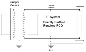
An earthing arrangement where the supply source is directly connected to earth, and the consumer installation metalwork is grounded via an independent local earth electrode that relies on soil path impedance for fault return.
IT System
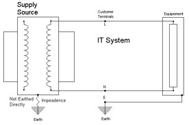
An earthing arrangement where the power source has no direct connection to earth (or is earthed only through a high impedance), while the installation's exposed conductive parts are connected to a local earth electrode.
Earth Fault Loop Impedance (Zs)
The total impedance of the complete metallic and earth return path traversed by earth fault current from the source transformer to the fault and back, determining prospective fault current (If≈ZsU0).
Residual Current Device (RCD)
A mechanical switching device incorporating a summation current transformer (toroid) that monitors current balance between live conductors and trips open when residual leakage current exceeds a rated threshold (IΔn).
RCCB
Residual Current Circuit Breaker; an RCD that provides protection against earth leakage and shock currents only, without built-in overload or short-circuit overcurrent protection.
RCBO
Residual Current Breaker with Overcurrent protection; a single combined device providing simultaneous protection against earth leakage, circuit overloads, and short circuits.
Arc Fault Detection Device (AFDD)
A protective device installed at the origin of a circuit that uses microprocessor technology to evaluate current waveforms for unique signatures of series or parallel electric arcing, tripping the circuit to prevent electrical fires.
Surge Protection Device (SPD)
A protective device designed to limit transient overvoltages from atmospheric origin or switching surges and divert dangerous surge currents safely into earth.

Earth Electrode Resistance Test (Three-Terminal Method)
A verification test using an earth resistance tester with an electrode under test (E) and two driven auxiliary spikes—a potential probe (P) and a current probe (C)—moved to check for stable, non-overlapping resistance areas.
Bathroom Zone 0
The interior region of a bathtub basin or shower tray, requiring electrical equipment installed within it to meet an ingress protection rating of at least IPX7.
Bathroom Zone 1
The volume directly above the bath basin or shower tray up to a height of 2.25m from the floor, requiring electrical equipment to possess an ingress protection rating of at least IPX4.
Bathroom Zone 2
The area extending 0.6m horizontally beyond the boundary of Zone 1 and up to a height of 2.25m, requiring electrical equipment to meet a minimum ingress protection degree of IPX4.
Purposes of Earthed Equipotential Bonding
Prevent shock hazard to persons and livestock. 2. Prevent fire hazard. 3. Protect the electrical installation and connected equipment. 4. Provide an alternative conducting path to allow fault current to flow, in order to operate the circuit protective device. 5. Limit the touch voltage between simultaneously accessible parts.
Two Causes of Electric Shock
Direct contact: Touching an installation part that is normally live under healthy working conditions.
Indirect contact: Touching a conductive part that is not normally live, but has become live as a result of an insulation fault (such as the metal frame of an appliance).
Two Factors That Determine the Intensity of Electric Shock
The shock current through the human body.
The duration of the shock.
Two Factors That Determine the Magnitude of Shock Current
The voltage of the supply.
The impedance of the human body and the contact with earth.
Earth Electrode Requirements for Small Installations (≤250A)
For installations with a supply rating not exceeding 250A, a single earth electrode is deemed sufficient under the following conditions:
Standard specification: A hot-dip galvanized-steel rod or pipe with a diameter of at least 16mm driven into the ground to a depth of at least 1200mm.
Environmental & mechanical factors: Depth and placement must account for potential mechanical damage and minimize the effects of soil drying and freezing.
Prohibited methods: Metallic pipes for flammable liquids or gases must never be used as an earth electrode or included in electrode dimensioning.
Electrolytic corrosion: Potential electrolytic corrosion must be accounted for when combining varied materials.
Function of the Earth Electrode
Primary purpose: Maintains an electrical connection between the general mass of earth and metallic parts of the consumer's installation, acting as a potential reference rather than a guarantee of zero touch voltage.
Fault handling: Remains continuously effective and capable of carrying earth leakage and prospective earth fault currents.
Soil dependency: Effectiveness relies directly on contact with the surrounding ground and soil type (e.g., heavy sticky soil provides a low-resistance path, whereas rocky soil creates difficulty in achieving good contact).
Location and Installation of the Earth Electrode
Positioning & driving: Typically installed outdoors near the meter cabinet and driven vertically into the ground, ensuring clearance from foundation work and underground services.
Rocky ground: If driven depth cannot be achieved, bury the electrode horizontally or use an alternative approved type; cutting the electrode to shorten it is strictly prohibited as it reduces contact area.
Clamping & sealing: Connect the earthing conductor using a dedicated clamp to provide a sound electrical and mechanical joint, then seal it with protective tape resistant to weather, chemicals, rodents, and termites.
Enclosure & inspection: House the termination inside an enclosure with a removable cover labelled "SAFETY ELECTRICAL CONNECTION DO NOT REMOVE", ensuring accessibility for inspection upon initial energisation.