Physics Quiz 3
 Call Kai
 Learn
Learn Practice Test
 Spaced Repetition
 Match
Match Flashcards
 Knowt Play
1/108

Earn XP
Description and Tags
Radiation measurement quantities, Radiation detection & measurement, External beam radiation therapy units
Name | Mastery | Learn | Test | Matching | Spaced | Call with Kai | Chat |
|---|
No analytics yet
Send a link to your students to track their progress
109 Terms
SED
skin erythema dose
Exposure
Amount of ionizations in air, produced by photons
Traditional unit - roentgen
SI - C/kg
valid up to 3 MeV
Exposure formula
X=Q/m
X - exposure (total charge of ions)
Q - charge (either + or -)
m - mass
Free Air ion chamber
Standard to define and calibrate radiation measurements
absolute dosimeter
Dmax
depth of the maximum dose
where scatter in = scatter out
increase E = increase Dmax depth
Fluence
total number of particles entering a sphere of small cross sectional area
Φ = N/a
units are cm^-2, m^-2

KERMA
Kinetic energy release per unit mass in a medium
units are Gy or J/kg
Absorbed dose
amount of ionizing radiation depositied per unit mass of material
units are Gy or J/kg
kerma vs dose
kerma - energy transferred from photon entering body to electron that it knocked out
dose - the energy that the knocked out electron absorbs/deposits in tissue as it travels

Skin sparing
max dose occurs below skin surface, protecting outer skin from severe damage

Build up region
starts at skin surface and extends to dmax
(once photon hits skin, secondary electrons are produced, and more energy is deposited, hence dose increases)
Dose buildup and Skin sparing

Mean energy to produce ion pair
33.97 eV/ion pair
Roentgen to Rad conversion
converts exposure to absorbed dose
1 Roentgen = 0.876 Rad (IN AIR!!)
then must convert to find dose within another medium
exposure to absorbed dose formula
to get dose in the medium

Fomula to convert chamber reading to exposure
X = M (Nx)(CTP)(PST)(PION)
X = exposure
M = electrometer reading
Nx = Calibration factor (given by calibration lab)
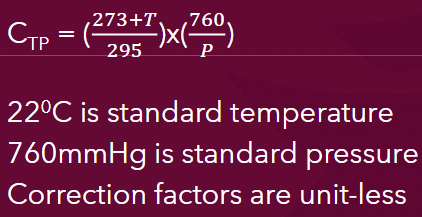
CTP = correction for temp and pressure
PST = correction for stem leakage
PION = correction for ion recombination - 1-2% lost
Gold standard computational method in rad therapy
Monte carlo algorithm
tracks primary and all other particles created by the primary interaction
used in treatment planning systems
Downside of monte carlo calculations
large computational requirements
(time, processing power, data storage)
E relationship with ionization rate
Increase E = increase ionization rate
Ionization chamber
collects the charge
radiation knocks electrons off gas atoms, which travel through and are attracted to opposing sides (anions - and cations +)

Electrometer
measures the charge
LET (Linear energy transfer)
energy deposited per unit path length
units - keV/um
Quality factor
used to account for differences in LET between radiation types

Equivalent dose
attempt to account for biological effects of different types of radiations as they interact with tissue
units - sievert or rem
1 Sv = 100 rem
Radiation machine calibration
accurate measurement of radiation
not sensitive due to high radiation level
Survey work
detect & provide rough measure of radiation levels in environment
sensitive but not very accurate
personnel monitoring
needs to be sensitive and measure cumulative radiation exposure
In vivo patient measurements
monitor amount of radiation patients recieve during treatment
types of radiation detectors
Gas ionization detectors
Ion Chambers
• Proportional Counters
• Geiger-Muller (GM) counters (survey meter)
Solid state detectors
TLDs
• Film
• Diodes
• MOSFETs (Metal oxide semiconductor-field effect transistors) (in vivo dosimetry)
• Polymer gel
• Scintillation (survey meters
Liquid dosimeters
• Calorimeters (standardization labs)
• Chemical
phantom
material for radiation measurement that can’t be tested on patient
mimics patient scattering and absorption
2 types of phantoms
Geometric - in a simple geometrical shape that doesn’t imitate patient shape
ex. cubes, “virtual water” (slabs of epoxy resin), water tanks
Anthropomorphic - designed to mimic shape of average patient
why is the free air ion chamber impractical for field use
its size

Parts of free air ion chamber
Beam from Source (S) is defined/collimated by a Diaphragm and passes between two parallel plates
2. High voltage is applied between the plates so that ions are collected
3. Length (L) are the limit for collection of ions to collecting electrode
4. Guard Wires – provide a uniform electric field
Collecting volume - where charge is collected and measured
Gas ionization detectors
Ion Chambers
Thimble chamber
calibrated every 2 years
collecting volume 0.1 to 1.0 cm3
Plane parallel chamber
pancake chamber
Extrapolation chamber (type of plane parallel chamber)
good for measuring surface dose

Extrapolation
using facts from a starting point to estimate a value that falls outside of given range
CTP (Correction for temperature and pressure)
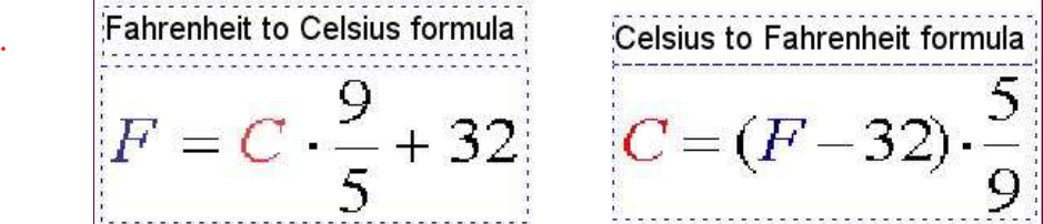
Convert F to C
What happens to particles when the temp drops
particles condense
higher remp = particles condense = more ionizations
Stem effect
radiation hits the stem/cable and creates extra ionization/charge = falsely increases reading
1-10%
Stem leakage
electrical charge leaks through the stem/cable or insulation when it shouldn’t = causes inaccurate electrometer reading
Ion recombination
loss of charge occurs when ions recombine with each other and never reach the collecting electrodes
Geiger Muller Counter
sensitive (detection) but not accurate
Annealing
heated to release residual signs as well as condition sensitivity
reset process
TLDs (Thermoluminescent dosimeters)
use lithium fluoride
reusable
wide dose range
not instaneous reading
OSL (Optically stimulated luminescence)
uses aluminum oxide
more sensitive than TLD
good long term stability (reusable)
wide dynamic range
2 part of film
Adhesive layer - connects base with emulsion layer
Emulsion - made of silver halide (silver bromide)
Optical density
measure of light attentuated by film
Pros vs cons of solid state detectors
pros - high spatial resolution, permanent record, inexpensive
cons - requires developing, strong photon energy dependence, not tissue equivalent, sensitive to light
RadioChromic Film
no silver halide
roughly equal to all energies
unexposed film is colorless, turns blue
insensitive to light
no processing, self developing
Diode
converts AC to DC
Diode array (grid)
wiring grid where diodes are placed at intersections
MOSFET
metal oxide semiconductor field effect transistor
measures threshold voltage which is proportional to radiation dose
Pros and cons of MOSFET
Pros - small & lightweight, immediate dose reading, reusable
Cons - limited life of 20,000 mV
Calorimeter
insulated container used to measure small amout of heat energy
absolute dosimeter for measuring absorbed dose
used to calibrate ion chamber
Electrometer
measures current from ion chambers
Teletherapy
radiation delivered with an external beam
2 types of accelerators
Linear accelerators - accelerate charged particles in straight line
Circular accelerators - microtrons, cyclotrons, synchrotrons, betatrons
Linear accelerator
speeds electrons to almost speed of light
accelerated with microwaves
e- beam can treat pts, or can hit target and produce photons
Isocenter
point in space which the gantry, collimator, and couch rotate around
SAD
Source to axis distance
100 cm
SSD
Source to skin distance
in older systems would always be 100 cm but pt would have to move between fields
now not always 100 cm (pt doesn’t have to move) (always changing with gantry angles)
Patient support assembly
treatment couch
now made of carbon fiber
6 degree of freedom - X,Y,Z, movement & roll, pitch, tilt
3 manufacturers of electron linear accelerators
Varian, Siemens, Elekta
Electron vs Photon (mono or polyenergetic)
Electron beam = monoenergetic
Photon = polyenergetic
How to find photon energy from electrom beam energy
Take 1/3 of the max
Waveguide
copper “pipe” where electrons are accelerated in LINAC
2 types: traveling wave & standing wave
held under high vacuum
Traveling wave
electrons surf traveling wave, but have to travel at same speed as electromagnetic wave
Circulator
prevents microwaves from reflecting back
(for traveling wave)
Standing wave
traveling wave moving down tube is reflected at end and travels opposite
electrons don’t surf
2 devices used to produce/handle microwaves
Magnetron & Klystron
Magnetron
standalone generator (makes mircrowaves from scratch)
take DC and directly converts into high power microwave radiofrequencies
more common in low energy LINACS
shorter lifespan, less expensive
Klystron
takes existing weak microwave signal and amplifies (has “extra step”)
require low energy microwave source (RF driver)
more common in high energy LINACS
more stable, more expensive
Power input to electron output

Treatment head
Xray target - photon mode only
Primary collimator
Scattering foil - electron mode only
Flattening filter - photon mode only
Monitor ion chamber
Field defining light
Movable (adjustable) collimators
Optical distance indicator (ODI)

Flattening Filter
high energy beams are more forward peaked so makes intensity more uniform
Reduces overall dose (quantity) but hardens beam (increases quality)
sits on a carousel
1 flattening filter per E !!!!!
Lateral horns
when the flattening filter overcompensates at surface
at less than 10 cm depth
Beam profile at different depths (flattening filter)
below 10 cm = lateral horns
at 10 cm = flat
more than 10 cm = forward peaked
FFF
flattening filter free
beam naturally has more intensity in the center
Symmetry
a pair of points equidistant from the CA must be within 2%
Flatness
all points must be within 3% at 10 cm deep across 80% of the field width
Monitor unit
amount of time to deliver 1 cGy, with 10×10 cm FS, to a specified depth (usually Dmax) at a distance 100 cm away
Monitor Ion chamber 3 purposes
provide feedback to maintain dose rate
track total dose
measure flatness & symmetry
Max field size at 100cm
40 × 40 cm
Primary vs seconday collimators
Primary = fixed and set max field size
Secondary = movable, “jaws”, transmission usually 0.5% or less
Light localizing system
projects light down on patient congruent with radiation field
between monitor ion chamber and collimators
What parts of treatment head are not in electron mode
target and flattening filter
scattering foil must be used to spread out 3 mm electron beam
What parts of treatment head are only in electron mode
Scattering foil
Electron applicator
Electron block
Applicator
“electron cone”
allows beam to be collimated down
Bend magnets
change direction of horizontal beam to vertical
either 270 or 90 degrees
High vaccum serves 2 purposes
Prevents arcing
prevents collison or electrons & air molecules
Why are LINACs usually never completely powered down
would lose vacuum, which takes a while to re-establish
Circulating cooling water - 2 purposes
carry excess heat from critical components
keep accelerating waveguide at a constant temp
Sulfur hexafluoride (SF6)
resides in waveguide to prevent arcing
checked each morning
How is the target moved out of beam path
compressed air
checked daily
Co-60
lower dose than LINACs
always on
half life - 5.26 yrs
How much of the beam do we usually measure
80%
Penumbra
edge of field that doesn’t receive whole treatment dose
Electron vs photon penumbra
Electrons have larger penumbra due to negative charges which repel each other
3 factors penumbra is caused by
Geometric penumbra
Transmission penumbra
Scattering of photons & secondary e-
What does geometric penumbra depend on
SSD, SDD, and source size