ME 4Y03 Midterm 2 Study
 Call Kai
 Learn
 Practice Test
 Spaced Repetition
 Match
 Flashcards
 Knowt Play
1/54

Earn XP
Description and Tags
we are so cooked lol
55 Terms
What are the 7 air standard assumptions?
Working fluid is air (not fuel/air/combustion mix)
Mass is constant throughout the cycle (real cycles vary ~7%, from fuel addition and exhaust blowdown)
Cycle is closed (gas exchange is replaced by recirculating air)
Heat exchangers model heat addition/rejection (idealisation: no internal combustion)
Intake/Exhaust occur at constant pressure (NA: Patm = 1, Boosted: Patm = > 1)
Compression/Expansion are isentropoc (Adiabatic & Reversive, Constant specific heat c)
Heat addition occurs at either Constant Volume, Constant Pressure, or both
What is the cold air standard?
A simplifying assumption used to analyze the ideal cycle.
The cold air standard value occurs at room temperature, where k=1.4
When comparing with a real engine (real working fluid), k=1.25
What is the value of k when comparing with a real engine (real working fluid)
k=1.25
What are the ideal processes of the Otto cycle?
The Otto Cycle has 4 ideal processes:
Isentropic Compression (1-2)
Constant Volume Heat Addition (2-3) → Idealises SI engines near instant spark ignited flame at TDC
Isentropic Expansion (3-4)
Constant Volume Heat Rejection (4-1 (5)) → Idealises exhaust blowdown and intake/exhaust strokes as single step
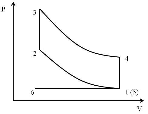
Derive the efficiency of the Otto Cycle

What happens to the Otto efficiency, as compression ratio increases towards infinity, and decreases towards 1?
As rc → ∞, ηt,otto → 100%
As rc → 1, ηt,otto → 0%
Therefore, the Otto efficiency only depends on rc and k !
What are the ideal processes in the Diesel Cycle?
The Diesel Cycle has 4 ideal processes:
Isentropic Compression (1-2)
Constant Pressure Heat Addition (2-3) → Idealises CI combustion, which is slower than SI’s flame injection/mixing
Isentropic Expansion (3-4)
Constant Volume Heat Rejection (4-1 (5))

What is the Diesel Cycle efficiency equation?

What happens to the Diesel Cycle Efficiency as Cutoff Ratio approaches 1?
As α→1 (heat added over a vanishing volume change), ηt,diesel → ηt,otto
Compare Otto, Diesel and Dual cycle efficiency at the same compression ratio
At equal rc: ηt,otto > ηt,dual > ηt,diesel
Otto adds all of its heat at the most favourable thermodynamic position (constant volume)
Dual adds some of its heat at constant volume, and the rest of it is added at constant pressure
Diesel adds none of its heat at constant volume (all is added at constant pressure)
Diesel heat addition happens at lower average pressure/temperature than Otto’s instantaneous constant-volume spike, so less of the added heat converts to net work
Therefore, the same heat input does less useful work when added over a volume change rather than all at once (at constant volume)
What are the ideal processes in the Dual (Limited-Pressure) Cycle?
The Dual (Limited-Pressure) Cycle has 5 ideal processes:
Isentropic Compression (1-2)
Constant Volume Heat Addition (2-3)
Constant Pressure Heat Addition (3-4)
Isentropic Expansion (4-5)
Constant Volume Heat Rejection (5-1 (6))
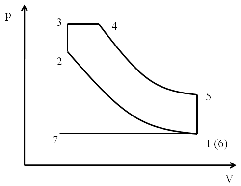
What is the Dual Cycle efficiency equation?

Why do compression ratios differ in SI and CI engines?
SI engines are limited to rc ≈ 10-12, due to knock
Raising rc increases pre-flame and end-gas temperatures, increasing autoignition risk ahead of the flame front
Compression heating gas towards autoignition is a hard ceiling for SI engines
CI engines require rc > 14
With no spark plug, fuel autoignition depends on reaching significant temperature/pressure by the compression ratio
What is a real SI engine’s actual indicated efficiency when compared to the Otto-cycle efficiency at the same compression ratio? (The headline number)
ηt ≈ 0.85 ηt,Otto , where the ideal Otto efficiency is evaluated for a real working fluid (k≈1.25)
What is the brake fuel efficiency for a real cycle?
ηbf = ηcηtηm
What are the major real-cycle losses, and what do they look like on a real-versus-ideal P-V diagram
There are 4 major real-cycle losses:
Pumping Loss: Pumping loop is “fatter”
Time Loss: Sharp top corner is rounded off
Direct Heat Loss: Expansion curve is below ideal
Exhaust Blowdown Loss: Expansion curve drops away near BDC

Explain Pumping Loss
The intake/exhaust loop net negative work:
Work required to move gases into and out of the cylinder during the gas exchange process (intake and exhaust strokes)
Explain Time Loss
Combustion isn’t instantaneous: It takes 30-60° of crank rotation.
Therefore, spark must be advanced before TDC to finish burning near TDC.
This costs more compression work and less expansion work than the ideal cycle assumes
This also shows that MBT (minimum spark advance for best torque) isnt simply at TDC
Explain Direct Heat Loss
Heat conducted through the cylinder wall to the cooling system during combustion/expansion
∴ The ideal cycles adiabatic assumption isn’t true here!
Explain Exhaust Blowdown Loss
The exhaust valve must open before BDC to let cylinder pressure fall to near-ambient by the time the piston starts the exhaust stroke
This sacrifices a small amount of expansion work to avoid larger penalty: Pushing high-pressure gas out through nearly closed valve
What are the minor real-cycle losses?
There are 4 minor real-cycle losses
Changing gas composition: Combustion converts reactants into products. ideal cycle assumes air throughout
Changing mass (CI only): Fuel addition adds mass to cylinder charge
Properties differ from air: Fuel vapor and combustion products (CO2 , H2O, N2) don’t have airs exact thermodynamic properties
Specific heat varies with temperature: By up to 30%, over the temperature range the cycle spans (~20-3600°C)
What are the levers to close the gap between the real cycle and the ideal cycle efficiency"?
There are 7 levers:
Raise rc: Raises ηt,Otto ceiling, rather than closing gap to it
Advanced Combustion Mode (E.g. HCCI): Attacks time loss by changing how combustion proceeeds
Boosting (Turbo/Super charging): Raises ρi , raising absolute power
Reduce Exhaust Backpressure: Attacks pumping loss (though it acts against exhaust aftertreatment devices, which add backpressure)
Exhaust Valve Timing (E.g. VVT/VVA): Attacks pumping loss
Spark/Injection Timing: Attacks time loss
Direct Injection (E.g. DISI): Reduces pumping loss by enabling throttle-less operation
What are the stages of SI combustion? And what mass fraction is burned in each?
There are 3 stages of SI combustion
Ignition and Flame Forward Development (0-5% burned)
Flame Propagation (5-90% burned)
Flame Termination (Final 5-10% burned)

Describe the Ignition and Flame Development stage of SI combustion
It is the 1st SI combustion stage, burning 0-5% of mass
A spark lights a small kernel of mixture near the electrodes
This early flame is fragile
This stage has the largest cycle-to-cycle variation
Electrode gap tradeoff:
Too small: Quenches flame nucleus (electrodes conduct heat away faster than the fledgling flame can sustain itself)
Too large: Reduces spark integrity (energy spread too thin to reliably ignite the gap)
Describe the Flame Propagation stage of SI combustion
It is the 2nd SI combustion stage, burning 5-90% of mass
The propagation speed depends on the following:
Turbulence, Swirl, Squish (in-cylinder motion that accelerates the flame front)
Type of fuel
Fuel/Air ratio
The Volume Burned > Mass Burned
30% of mass burned occupies 60% of cylinder volume
Early flame kernels are less dense than the unburned charge they displace
Roughly 2/3 of mass is burned by TDC, complete by about 15° CA after TDC
Describe the Flame Termination stage of SI combustion
It is the 3rd SI combustion stage, burning the final 5-10% of mass
The end gas is close to the cool cylinder wall
Turbulence is damped by the wall boundary later
Burning “dies off” slowly
This is where knock occurs, as the last end-gas pocket can autoignite
What is Knock?
Knock is a pinging noise from an SI engine undergoing abnormal combustion
Generated by shockwaves produces when unburned end gas ahead of the flame front autoignites
What are the consequences of Knock?
There are 6 consequences of Knock:
Noise and vibration
Increased heat transfer
Mechanical damage
Pre-ignition: Hot spots left by knock can trigger ignition before the spark fires
Reduced power/efficiency
Carbon deposited in cylinder chamber
What are the factor groups that control Knock?
There are 3 factor groups that control knock:
Temperature/Pressure/Density
Flame Speed/Ignition Delay
Composition
Raising end-gas temperature/pressure, or slowing the flame front, raises Knock.
How does the factor group Temperature/Pressure/Density control knock?
Compression ratio
Induced charge mass (turbo / super charging)
Inlet/Outlet coolant temperature
Spark timing
Power Output
Cycle-to-cycle variation, carbon deposits
How does the factor group Flame Speed / Ignition Delay control knock?
Turbulence, engine speed
Flame travel distance
Combustion chamber shape, engine size
Spark plug / exhaust valve location
How does the factor group Composition control knock?
Octane rating
Fuel/Air ratio
Humidity of air
What is the Octane Number?
Octane Number is a fuels ability to resist knock
It compares a fuel’s knock tendency against a n-heptane/iso-octane blend
Higher is better for SI: Pure iso-octane scores 100, pure n-heptane scores 0
Lower self ignition temperature = higher knock tendency = lower octane number
What is RON and MON? How do they differ?
RON: Research Octane Number
Measured under milder conditions
Lower speed
MON: Motor Octane Number
Measured under harsher conditions
Higher speed
More advanced spark timing
MON ≤ RON, as MON is harsher, so it will knock more and have a lower Octane Number

What is AKI?
AKI = Anti Knock Index = ½(RON + MON)
AKI is a compromise summary figure, used in Canada, the US, and Brazil, typically 4-6 points below RON)
Why does Diesel fuel have such a low Octane Number?
Combustion combustion relies on auto ignition, so it must have a low octane number. High-octane gasoline would refuse to autoignite reliably in a CI engine
How can chamber geometry be designed to avoid Knock?
There are 4 levers to geometrically avoid knock
Minimize Flame Travel Distance: Faster/more complete combustion before end gas has time to autoignite
Keep Exhaust Valve & Spark Plug Close Together: Reduced end-gas time near hottest surfaces
Ensure Sufficient Turbulence: Speeds up combustion
Put End Gas in Cool Part of Chamber: Lower end-gas temp lowers autoignition risk
What is MBT? What are the two penalties it cancels out?
Minimum spark advance for best torque
The spark timing at which the two opposing penalties cancel out, producing maximum brake torque
Too Early: Work is done against piston (combustion pressure rises before TDC, while piston is still moving up)
Too Late: Peak pressure is reduced (combustion finishes wel after TDC, on the lower pressure part of the expansion stroke)
How does Speed affect MBT?
MBT advance rises with speed
Faster engine speed means less time per degree of crank rotation, so ignition must start earlier
How does the air/fuel mixture affect MBT?
MBT advance rises as mixture leans
Lean flames are slower, holding up the partial burn limit
What are the different types of Fuel Injection Systems?
There are 3 main types of fuel injection
SPFI: Single Point Fuel Injection → One injector upstream of throttle body, serving all cylinders
MPFI: Multi Point Fuel Injection → One injector per cylinder, in the intake port
GDI/DISI: Direct Injection → Fuel injected straight into the cylinder
What is Stratified Low Load Operation?
An operation mode for engines with DISI (direct injection)
At Low Load: Fuel injected late in compression stroke
Rich, ignitable pocket near spark plug, while elsewhere is globally ultra-lean
Pressure stays high enough to avoid pumping loss penalty of throttling
At Moderate/Heavy Load: Fuel injected during intake stroke, allowing full mixing
What are the Advantages / Costs / Companions of Direct Injection?
Advantages
Increased volumetric efficiency
Reduced knock → Higher rc possible = higher ηt = 30% lower bsfc (brake specific fuel consumption)'
Reduced pumping loss (throttle-less)
Lower charge heating near cylinder wall → lower direct heat loss
Costs
Higher cost
Potential Emissions Tradeoffs
Often Paired With
Turbo/Super charging, VVT
Variable length intake manifold
Water injection, EGR
How does load control differ between SI and CI engines (“quality control”)
SI meters air first, via throttle, then adds just enough fuel to stay stoichiometric
∴Power changes by how much mixture enters the cylinder (the Quantity)
CI always ingests the same amount of air, but varies how much fuel is injected into it
∴Power changes by changing mixture Quality (how rich locally burning F/A is)
Therefore, CI engines have less pumping loss than a throttled SI engine at partial loading

Compare DISI vs CI Injection Timing
DISI (injection differs by load):
Low load: Injected a few crank angles before TDC (during compression stroke) (stratified) → (Rich, ignitable pocket near spark plug, while elsewhere is globally ultra-lean)
Moderate/Heavy load: Injected during intake stroke, giving time to fully mix
CI:
Fuel only injected a few crank angles before TDC, at essentially every load
Therefore, CI combustion always depends on autoignition timed precisely to TDC, not on spark that can fire whenever the mixture happens to be ready
What are the combustion chamber types?
Direct Injection (DI): Fuel is injected straight into a bowl in the piston crown
Indirect Injection (IDI): Fuel is injected into a small pre-chamber, connected to the main cylinder by a narrow throat
It generates strong swirl, as burning charge jets back into the main chamber
Trades some efficiency for combustion robustness, and still promotes mixing even with lower quality equipment

What are the stages of CI combustion?
CI combustion has 4 stages:
Ignition Delay
Pre-mixed Comustion
Mixing-Controlled Combustion
Late Combustion
Plot the stages of CI combustion on a CA vs (Pressure and HRR) plot

When does the Ignition Delay stage of CI Combustion Start/End?
It is the 1st stage of CI combustion
Begins at the start of fuel injection
This is detected experimentally by a needle-list indicator
Ends at the start of combustion
This is detected experimentally by either (a) change of slope in heat release, or (b) luminosity detector (light emission)
What happens during the ignition delay stage of CI combustion?
2 Process groups happen during ignition delay:
Physical Process (3 parts)
Atomization
Fuel injection is a high pressure event; Modern high-pressure common rail (HPCR) systems inject at ~2000 bar, into a cylder of only ~10-20 bar. This pressure difference causes the atomization of the liquid jet
Vaporization
Mixing of fuel vapour with air
Chemical Process
Pre-combustion reactions among fuel, air, residual gas → building towards autoignition
What factors control the ignition delay stage of CI combustion?
There are 7 factors that control ignition delay
Injection timing
Injection quality
Droplet size, injection velocity, rate
Intake air temperature/pressure
Engine speed
Combustion chamber design
Swirl
How long is the ignition delay stage of CI combustion? How does a long/short delay change combustion?
Ignition delay is between 0.4-3ms depending on engine type
Long ignition delay is bad → Late ignition can push combustion into the expansion stroke, causing incomplete combustion, reduced power, and low fuel conversion efficiency
∴ Shorter ignition delay allows for faster, more complete combustion (closer to ideal curve instant constant volume)
Higher rc and turbocharging both shorten delay (higher temp/pressure speed up ignition)
Describe the Pre-mixed Combustion stage of CI combustion
The 2nd stage of CI combustion
All fuel mixed during ignition delay burns nearly at once when autoignition triggers
High heat releases over just a few crank angles
Produces “Diesel Knock” (not the same as SI knock): The rapid pressure rise/spike itself, from the plot
“Smooth” combustion: Pressure increases within ~0.1-0.3 MPa per crank angle
A longer ignition delay = more pre-mixed fuel = larger pressure spike (diesel knock)
Describe the Mixing-controlled Combustion stage of CI combustion
The 3rd stage of CI combustion
Heat release is now controlled by the rate at which fresh mixture becomes available
Atomisation, vaporization, and pre-combustion reaction happen continuously as fuel keeps injecting
Desirable to keep this process close to TDC because:
Higher efficiency (peak pressure closer to TDC)
Reduced soot emission
The longest stage in the pressure/HRR chart
Most directly under engine designers control
Describe the Late Combustion stage of CI combustion
The 4th stage of CI combustion
Fuel that failed to burn during stages 2-3 combust:
Over-lean/over-rich local pockets
Wall wetting
Fuel trapped in crevices
Burns slowly, well into expansion stroke, contributing little work
Where unburned hydrocarbon and soot emissions originate