fdsc4210 lecture 20 - 23
 Call Kai
 Learn
 Practice Test
 Spaced Repetition
 Match
 Flashcards
 Knowt Play
1/38

There's no tags or description
Looks like no tags are added yet.
39 Terms
Mechanisms of thermal energy transfer
Radiation: Heat transfer without a substance/medium → via electromagnetic waves
q dot = σAe(ΔT)4
Conduction: heat transfer through a substance → via physical contact
q dot = (kAΔT)/x
Convection: heat is carried along with a substance → via fluid motion
q dot = hcA(ΔT)
Where q = amount of energy, q dot = energy transfer per unit time = dq/dt [=] J/s or Watt (AES = Btu/hr) → similar to m dot = dm/dt
Fourier’s First law of conduction
Assume heat transfer in steady state → heat in = heat our
The rate of heat flow (q dot) at any point is proportional to the gradient:
q dot ∝ dt/dx
q dot is proportional to the area of material that is at right angles to the direction of heat flow: q dot ∝ A
q dot also depends on the nature of the material (k) through which the heat flows
Fourier’s first law of conduction: q dotx = -kA(dT/dx)

Heat flux
rate of heat flow per unit area (q’)
q’ = -k(dT/dx)
Depends only on thermal conductivity and temperature gradient

Thermal conductivity
a characteristic of each material (k), the coefficient of conductivity
k [=] q dotx/[(A(dT/dx)] → Watts/mK
Since the rate depends on temperature difference, Celsius and Kelvin can be used interchangeably
AES units for k are Btu/(hr x ft x R) → Fahrenheit and Rankine can be used interchangeably
Typically:
Metals have high conductivity due to free movement of e-
Non metals are near of below 1 W/mK
Water: 0.6 W/mK for liquid and 2.25 W/mK for ice!!!!
Oils: lower than water
Gases: very low (0.01 - 0.02 W/mK)
Materials with trapped air like cork and fiberglass are very low → good insulation

Thermal conductivities of frozen foods
• Higher thermal conductivity of ice than liquid water affects the rates at which foods freeze and thaw. (Kice 2.25 W/mK > Kliquid 0.6 W/mK)
• Since heat must be removed from the outer surface, freezing begins there and progresses inwards (freeze from outside in). This increases the thermal conductivity and thus the rate of heat removal.
• Food thaws from the outside as heat is added. The outer liquid layer that forms reduces thermal conductivity and acts like an insulator around the remaining ice (thawing from outside in). This slows thawing.
So q dot freezing > q dot thawing → thawing takes longer than freezing

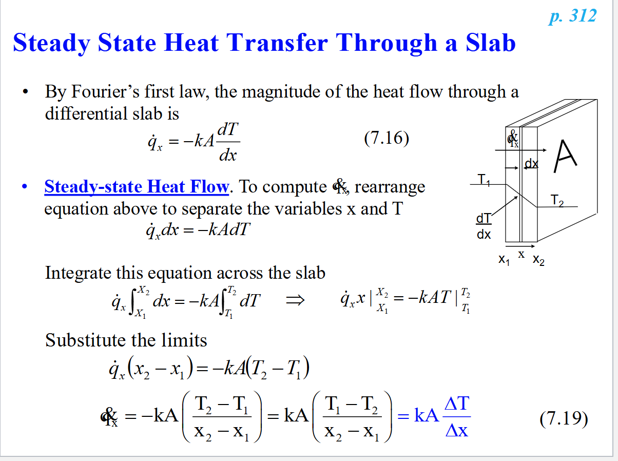
Steady state heat transfer through a slab
Using Fourier’s first law, the magnitude of heat flow through a differential slab is q dotx = -kA(dT/dx)
Doing maths… q dotx = kA(ΔT/Δx)
Where ΔT is T1 - T2 or absolute T diff so you don’t have to worry about signs
Driving force and resistance
In electricity, Ohm’s law states:
Current = voltage/resistance or I = E/Ri = driving force/resistance
Heat flow can also be put in the same form if we take:
Heat flow (q dotx) to be analogous to electric current (I)
Temperature drop to be analogous to voltage (E)
And define resistance as R = (x1 - x2)/kA = (Δx/kA)
The heat conduction equation then becomes:
q dotx = ΔT/R = driving force/resistance
So… Resistance to heat flow:
Increases with increasing thickness (Δx)
Decreases with increasing area (A)
Decreases with increasing thermal conductivity (k)
And is inversely proportional to q dotx
R [=] oC/W or oF-hr/Btu

Thermal insulation
R-value is used in classifying insulation materials in commericial practice
R value = Δx/k [=] m2oC/W or oF(h-ft2)/Btu
OR R value [=] 1/[W/(m2-oC)] → thus R-value is the inverse of heat flux through a material per degree temperature difference between its two sides
A higher R value means better insulation because you decrease heat flux

Determining the temperature profile
Temperature profile expresses temperature (T) as a function of distance (x)
dT/dx is the derivative of the temperature profile
Integration is the inverse of differentiation → integrate qdotx = -kA(dT/dx) to get temperature profile
Eventually get T = T1 - (q dotx/kA)x
• In steady state, q dotx, k and A are all constants so q dotx/kA must also be
a constant. Thus equation (7.25) is the equation for a straight line
with intercept T1 and slope equal to: -q dotx/kA
•We can conclude that the temperature profile inside the slab is a
straight line sloping downward (negative slope) as shown.

Heat conduction through a hollow cylinder or pipe
3 approaches to account for the fact that the area through which heat passes increases continuously through the pipe
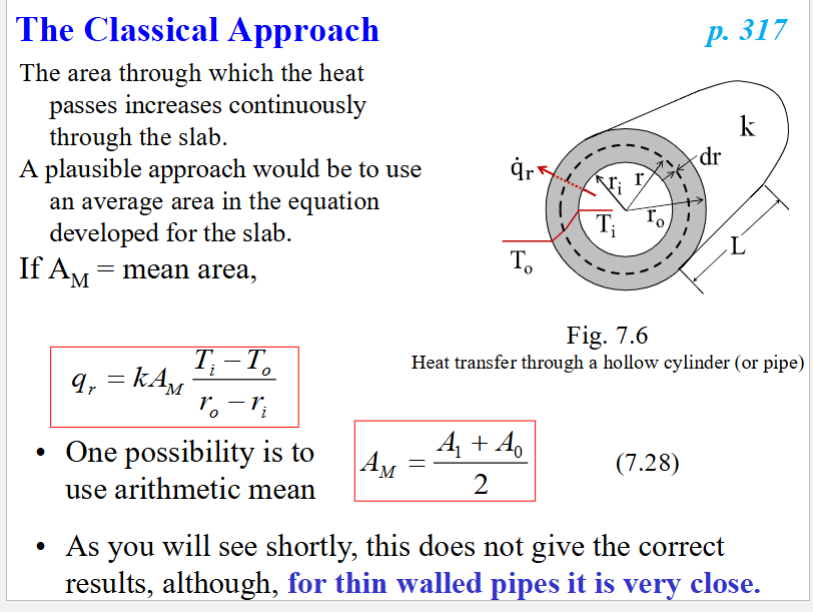
Classical approach: AM or mean area → using arithmetic mean (Ai + Ao)/2
This one is not correct, only close to correct results tor thin walled pipes
Analytical approach: differential shell
Log mean area
Analytical approach for heat conduction through a pipe
The differential shell: imagine a thin cylindrical shell within the wall of the real cylinder with radius r and thickness dr
The area of that shell would be A = 2pirL
The differential equation: by Fourier’s first law, the rate of heat flow through the shell would be q dotr = -kA (dT/dr) → substitute in area then do maths…
q dotr= 2kpiL(Ti - To)/ln(ro/ri)

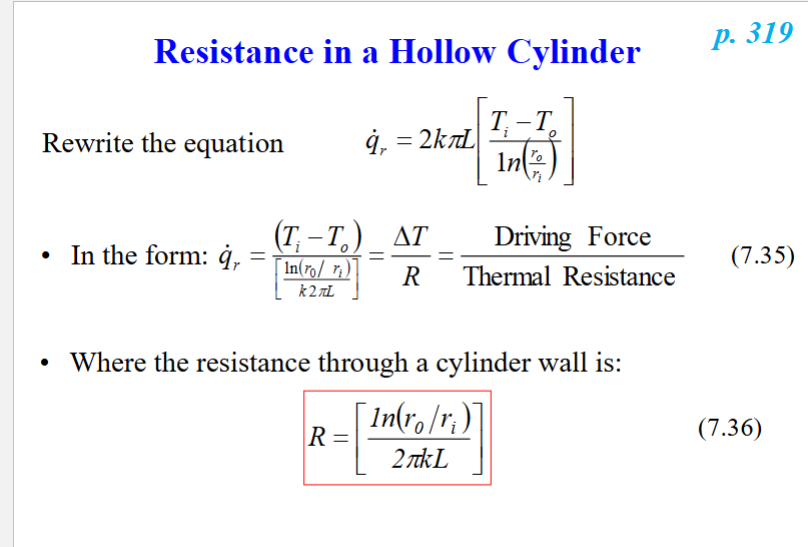
Resistance in a hollow cylinder
For the analytical approach: q dotr= 2kpiL(Ti - To)/ln(ro/ri)
Put it into form of driving force/thermal resistance:
q dotr = ΔT/R, where R = [ln(ro/ri)/(2pikL)]
Log mean area approach for heat conduction through a pipe
Compare the classical and analytical equations, set them equal to each other
ALM = log mean area = (Ao - Ai)/[ln(Ao/Ai)]
Final equation:
q dotr = -kALM[(Ti - To)/(ro - ri)] = kALM(ΔT/Δr)
q dotr = k2piL[(Ti - To)/ln(ro/ri)]
and for resistance: q dotr = ΔT/R, where R = Δr/(kALM)

Temperature profile in a pipe
Temperature is a linear function of the natural log of the radius
The actual temperature profile is like a slight concave line between inner and outer radius
T = Ti - (q dotr/(k2piL))ln(r/ri)
T = Ti - (2.303q dotr/(k2piL))log(r/ri)


Heat conduction through slabs in series
The heat goes through one slab at a time: assume steady state, at any point in the slab, heat in = heat out
The q dot x (rate of heat flow) across each slab should be the same
for the thermal resistance, q dotx = (ΔT)overall, across all layers/(sum of all resistances)

Shortcut for determining thermal conductivity and controlling resistance to heat flow in multilayer structures
heat flux = q dotx/A = k(ΔT/Δx), will be equal for each layer
The material with the largest slope (ΔT/Δx) will have the lowest thermal conductivity (k) because they are inversely proportional. This material will also have the controlling resistance to heat to heat flow because resistance is inversely proportional to k → lower k = higher R
This is called the controlling resistance to heat because it controls the heat transfer rate

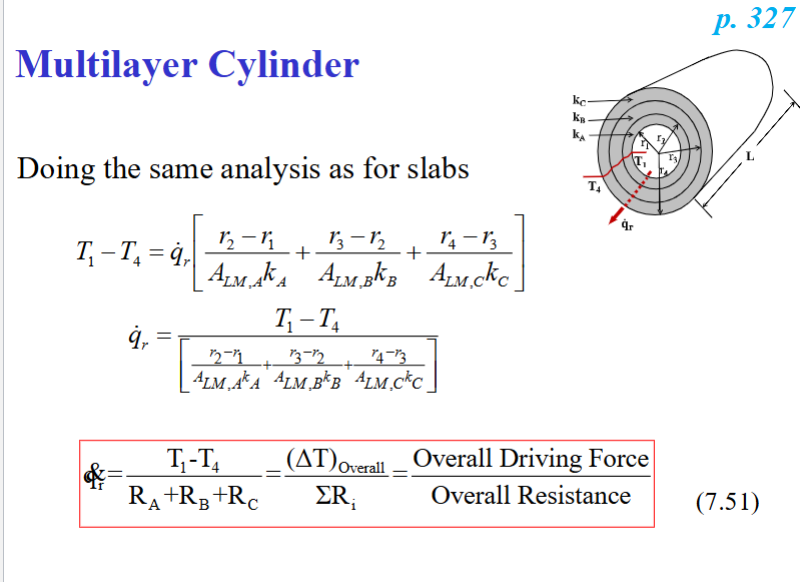
Heat conduction for a multilayer cylinder
same for slabs in series:
for the thermal resistance, q dotx = (ΔT)overall, across all layers/(sum of all resistances)
Conduction for slabs in parallel
The heat is going through all the slabs at once, so the q dot (rate of heat flow) for each slab will be different.
The total heat flow will = the sum of the heat flows in each slab.
The same applies to the q dot (rate of heat flow).
1/RT = 1/R1+ 1/R2 + 1/R3 ….

Natural vs forced convection
Natural: An increase in internal energy of a fluid increases the volume and decreases the density. If heating takes place at the bottom or cooling at the top, a natural circulation develops that will move energy throughout the system.
Forced: movement of fluid by use of an external device → fans, pumps, stirrers, etc.

Newton’s Law of Cooling
Fluid at Tf is flowing past an object at Tw. If Tw > Tf, heat is transferred from the object to the fluid and the object starts to cool down.
Newton proposed that rate of cooling is proportional to the area (A) of contact and the ΔT between the object and the fluid:
q dot = hcA(Tw - Tf) = hcAΔT
Where hc is the convective heat transfer coefficient
Convective heat transfer coefficient
hc, has units of W/(m2K) or Btu/(hrft2oR)
It depends on many factors and is determined experimentally → IT IS NOT A MATERIAL PROPERTY! It is a SYSTEM property. depends on:
Nature of fluid (viscosity, Cp, k, ρ) flow properties of stream (v), geometry of system (Size, shape), ΔT
k vs. hc, recall that by Fourier’s law, q dot = kA(ΔT/Δx)
With Newton’s law, q dot = hcA(ΔT)
Approaches to estimate hc
Determine experimentally for each situation and tabulate → too many variables, and they could change, thus not very convenient
Derive an equation analytically → too complicated
Develop an equation by dimensional analysis → use experiments to determine final equation → this is what we do
Buckingham’s pi theorem
If you have a function that relates n variables,
If those variables can be expressed in r fundamental dimensions,
Then you can find n – r independent dimensionless numbers (called pi’s) that are combinations of those variables.
A new function can be found that relates these dimensionless numbers.
The final form of the function is determined experimentally.
Dimensional analysis
A method of establishing the relationships between different physical quantities by identifying and relating their fundamental dimensions.
The fundamental dimensions are length (L), mass (m), time (t), temperature (T)
First step is listing the variables involved in what you are solving for (in this case hc), then finding their fundamental dimensions → from there you can calculate how many pi’s there are (n - r) → then determine the relationship between the dimensionless numbers experimentally → for hc we have the Nusselt number (Nu), Reynolds number (Re), and Prandtl number (Pr)
Nusselt equation
Nu = CRebPrd
C, b, and d are constants that are determined experimentally → this equation varies based on all the variables ever


Dimensionless numbers and their interpretation
Nusselt number = pi1 = (hcd)/kfluid
Represents ratio of heat transfer by convection to heat transfer by conduction → large Nu indicates efficient convection heat transfer
Reynolds number = pi2 = ratio of inertial to viscous forces (ρdv/η = Re)
Prandtl number = pi3 = (Cpη)/kfluid → when you multiply numerator and denominator by 1/ρ you see that Pr represents ratio of momentum diffusivity to thermal diffusivity
Large Pr indicates momentum transfer (how fast fluid moves away) is dominating. Small Pr indicates heat transfer (how fast fluid is heated) is dominating

Heat exchanger
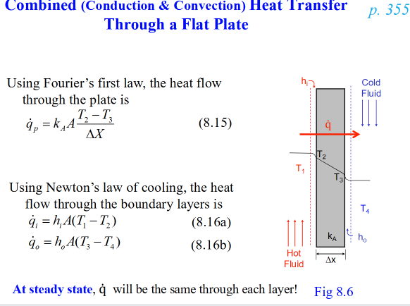
A typical plate heat exchanger used for heating and cooling of liquid food consists of many parallel plates that separate thing parallel cavities
Transfers heat by a combination of conduction and convection
At steady state, the rate of heat transfer through each layer is the same
q dot = (AΔToverall)/(A x sum of resistances)
Double pipe (tube in tube), parallel (Para flow), scraped surface, shell and tube, cross flow

U, new heat transfer coefficient
U = 1/(A x sum of resistances)
Units if W/(m2K) or Btu/(hr ft2 R)
New equation: q dot = U A ΔToverall
Expresses heat transmission capability of system rather than heat resistance


Combined heat transfer through a hollow cylinder
q dot = UiAiΔToverall = UoAoΔToverall
Uo = Ui (ri/ro)

Fouling
When films of products or heating/cooling media deposit on the surface
This introduces additional layers and increases the total thermal resistance
All industrial heat exchangers undergo fouling after extended use and show a decrease in performance
So you must consider the resistance of the inner fouling layer and outer fouling layer when calculating total resistance
1/Ufouled = Rf + (1/Uclean)
Where Rf = fouling factor → determined experimentally
Double pipe or tube in tube heat exchanger
Consists of large diameter pipe with concentric small diameter pipe inside the larger pipe
One fluid flows in the inner pipe, and the other fluid flows in the annulus (outside pipe)
Simple, easy, cheap
Flow can be counter current (fluids flow in opposite directions) or co-current (parallel, fluids flow in same direction)

counter current VS Co current or parallel
The temperature profile for a counter current heat exchanger has the ΔT between the fluids pretty consistent, whereas the ΔT for the co current gets smaller as it moves toward the second point.
q dot = UAΔT = UiAiΔT = UoAoΔT holds true only at a point in a heat exchanger
Must use ΔTLM or LMTD to calculate q dot because the ΔT is different at point 1 and 2
ΔTLM depends on flow pattern, ΔTave does not.
ΔTLM, counter current > ΔTLM co current. Since the q dot and U for the 2 systems should be the same, that means the area required for a counter current system is < the area required for a co current system → save space and cost
Co current used for highly viscous fluids to reduce entrance viscosity, increase Re and hc to make pumping easier. Also better to exert less thermal stress on pipe

ΔTLM and ΔTave
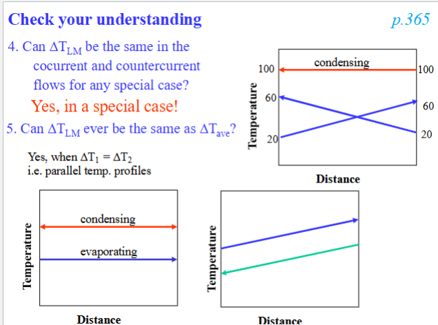
ΔTLM can be the same for cocurrent and counter current flows if one of the fluids is going through a phase change. Then the direction of the second fluid wouldn’t affect the ΔTLM
ΔTLM = ΔTAve when ΔT1 = ΔT2 → parallel temp profiles
This would also make ΔTLM = 0… so we use L’ Hospital’s rule: If the limit of function is in the form 0/0 or infinity/infinity as a variable approaches some value, then the derivatives of the numerator and denominator are evaluated separately and the limit is applied again. Basically the ΔTLM = ΔT1 = ΔT2
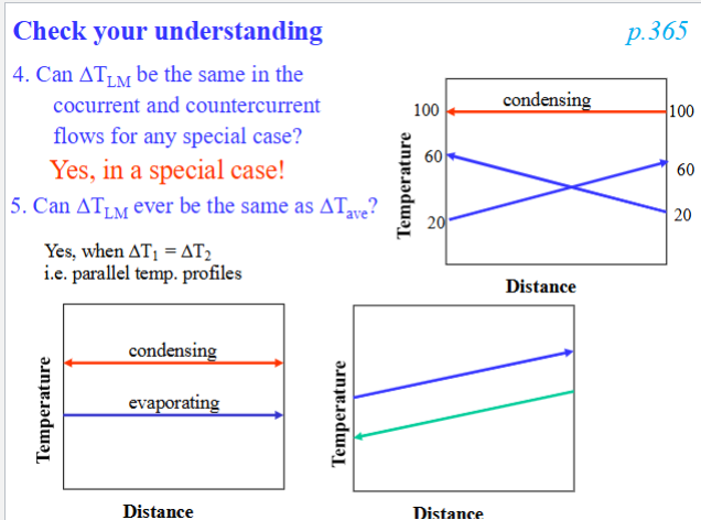

Plate heat exchanger
A pack of corrugated stainless steel heat transfer plates held together in a frame
Corrugation increases turbulence for more efficient heat transfer and less surface fouling
Open and blind holes with different gasket configurations in each plate generate varying flow pattern → keeps the 2 fluids separate
The two media flow in a series of alternate channels (cavities)
Several plate packs are put together as separate sections for heating, heat regeneration and cooling in the same frame.
For the Re, use De for the Diameter. Recall De= 4hr = 4(cross sectional area/wetted perimeter) = 2G
Where G = gap size → Re = (2Gρ<v>)/η

Shell and tube heat exchanger
Can be 1 shell pass and 1 tube pass (1:1 exchanger) → counter current temp profile
Or 1 shell pass and 2 tube pass (1:2 exchanger) → this temp profile will have one of the fluids go counter current and then co current

Scraped surface heat exchanger
• Used for heating/cooling of viscous materials and liquid solid suspensions, e.g. pastes, purees, margarine, concentrates, etc.
• Like a double pipe heat exchanger with a jacketed cylinder containing steam/refrigerant, internal rotating shaft, and fitted with wiper blade.
• The rotating scrapers or wiper blade continually scrape the surface, preventing localized overheating/freezing and giving rapid heat transfer.
Cross flow heat exchanger
gas flows past heating or cooling fluid in pipes

Pasteurization system
In order:
Balance tank to keep fluid level: keeps consistent NPSHA to prevent cavitation, sloped downward to fluid flows down
Centrifugal pump → Regeneration section for preheating → timing pump (+ displacement) → heating section, counter current to heating fluid → holding tube
Goes to thermometer to measure T and flow diversion device will decide if it continues to cooling or must be sent back to balance tank
If it is all good to go, it acts as a starter stream and goes through the regeneration section to help preheat the raw feed because its gonna get cooled down anyway in the cooling section → keep pressure of finished product stream higher than raw feed so that any hidden leaks would only go from product to raw and not raw to product
After passing through cooling section with parallel flow, it goes through a vacuum breaker → this is because as it cools, it creates a vacuum that would then suck air in and cause contamination
Then it goes to get packaged

Regeneration efficiency
regeneration efficiency = η’ = (ΔTfeed in regen/ΔTstarter maximum)100
Increase efficiency by…
