Multi Checkride - Flight
 Call Kai
 Learn
Learn Practice Test
 Spaced Repetition
 Match
Match Flashcards
 Knowt Play
1/39

There's no tags or description
Looks like no tags are added yet.
Name | Mastery | Learn | Test | Matching | Spaced | Call with Kai | Chat |
|---|
No analytics yet
Send a link to your students to track their progress
40 Terms
When would you do an emergency descent?
Rapid descents performed to reach a safer altitude during in-flight emergencies or hazardous conditions.
Reasons:
1. fire
2. rapid depressurization
3. onboard medical emergencies
4. avoiding extreme weather
5. cabin smoke
Engine Roughness Troubleshooting
Section 3-21
1. Alternate Air/Carb Heat - Open/On
if using carb heat, always use FULL carb heat
If roughness continues after one minute:
2. Alternate Air/Carb Heat - Close/Off
3. Mixture - Adjust for maximum smoothness
4. Fuel Pump - On
5. Engine Gauges - Check
6. Mag Left/Right Switches - Individually Select OFF and ON
7. Run on most satisfactory magneto with REDUCED POWER AND FULL RICH MIXTURE and continue to nearest airport
Essentially just troubleshooting induction air, fuel injector nozzles, ignition problems, or too lean/rich mixture - can also test cross feed
Engine Overheating Troubleshooting - High Oil/Cylinder Head Temperature
1. Cowl Flaps - Open
2. Mixture - Enrichen
3. Power - Reduce
4. Airspeed - Increase
5. Monitor Oil Pressure Gauge
6. Land as soon as practical if problem persists
Carburetor Icing
Signs
1. Drop in RPM
2. Engine Roughness
Response
Follow Engine Roughness Checklist
1. Carb Heat - On - MAKE SURE IT’S FULL HEAT
If roughness continues after one minute
2. Carb Heat - Off
3. Mixture - Adjust for maximum smoothness
4. Fuel Pump - On
5. Engine Gauges - Check
6. Mag Left/Right Switches - Check ONE at a time
7. Run engine on most satisfactory magneto at REDUCED POWER and MIXTURE RICH to nearest airport/precautionary landing
Induction Icing
Signs
Roughness
Loss of RPM
Response
Complete Engine Roughness Procedure
Loss of Oil Pressure / Oil Leak
1. Verify affected engine
Low Oil Pressure
2. Throttle (affected engine) - Minimum Required
3. Propeller (affected engine) - Decrease
IF ACCOMPANIED BY HIGH OIL TEMPERATURE OR EVIDENT OIL LEAK
4. SECURE AFFECTED ENGINE
Make sure you configure the A/C before shutting down/securing the engine with the oil leak
Loss of Fuel Flow (EIS)
1. Fuel Pump (affected engine) - On
if normal operation is not re-established, turn the fuel pump back to off
2. Verify if there is a fuel leak
if there is a fuel leak, turn the fuel selector back to off and secure the engine
Single Alternator Failure
1. Verify failure by checking ALTR AMPS indication (should be 0)
2. Reduce Electrical Load below 65 Amps (60 if on the ground)
turn any unnecessary lights off, unplug items from USB ports, avoid uneccessary radio calls
3. Failed ALTR Switch - Off
4. Failed ALTR Circuit Breaker - Reset
5. Failed ALTR Switch - On
If alternator still failed
6. Failed ALTR Switch - Off
7. Monitor ALTR Amps indication (maintain less than 65 AMPS/ 60 on the ground)
Note that a singular alternator can support up to a 65 amp load and thus can support the system
Dual Alternator Failure
1. Verify Failure
Attempt to Reset Alternators
2. Failed ALTR Switches - Off
3. Failed ALTR Field Circuit Breaker - Reset if tripped
4. Filed ALTR Switches - On
If only ONE alternator Resets
5. Operating ALTR Switch - On
6. Failed ALTR Switch - Off
7. Maintain less than 65 Amp electrical load (60 on the ground)
8. Monitor Ammeter
If NEITHER Alternator Resets
9. Both ALTR Switches - Off
10. Electrical Load - SHED in less than 3 minutes
1. Non ess bus breaker - Pull
2. Lighting bus breaker - Pull
3. Avionics bus breaker - Pull
4. Avionics Master Switch - Off
5. Emergency Batt - Verify Arm
To ensure 30 minutes of battery life
11. Batt amps - 20 Amps maximum
12. Pitot heat - 15 minutes usage
13. Comm Radio - 3 minutes usage maximum
Once EMER BATT ON illuminates
14. Proceed to Complete Electrical Failure Checklist
Alternators and Main Bat Failure - Complete Electrical Failure Checklist
1. Emergency Bat Switch - Verify Armed
2. Stby Flight Instrument - Verify Operational
3. Aircraft Control - Maintain using PFD and Standby Instrument
4. BATT MASTR Switch - OFF
5. ALTR L/R SWITCHES - OFF
Prior to Landing
6. Landing Light will be inoperative
7. Landing Gear - MANUALLY EXTEND
Vaccuum System Failure
The Piper Seminole does not have any vaccuum systems as far as I am aware
Pitot/Static System (Mast) Malfunctions -
Pitot Tube Blockage
Airspeed drops to 0
Pitot and Drain Blockage
Airspeed acts like altimeter
Static Port Blockage
Airspeed acts like reverse altimeter
Altimeter freezes
VSI drops to 0
Checklist
1. Pitot Heat
2. Alternate Static Air (Pulls from cabin which is lower pressure)
Increase in indicated altitude and airspeed
VSI show climb then level off
PFD/MFD Malfunction
1. Reversionary Mode
2. Consult Checklist
If PFD fails, the following will be inoperative:
COM 1, NAV 1, GPS 1, Traffic, GFC 700 Autopilot
If MFD fails, the following will be inoperative:
COM 2, NAV 2, GPS 2, XM, DME, ADF, ESP (Garmin Electronic Stability and Protection)
Landing Gear Malfunction
BEFORE EXTENDING GEAR MANUALLY
1. Circuit Breakers - Check
2. BATT MASTR Switch - On
3. ALTR L/R - Check
MANUAL EXTENTION OF LANDING GEAR
4. Airspeed (BELOW 100KIAS)
5. Gear - DOWN
6. Emerg. Gear Extend Knob - Move wire guard and PULL
7. Gear Position Indications - 3 GREEN
8. Leave emergency gear extension knob out
Flap Malfunction
1. See if you can put the flap back up
2. Land with no flaps if you can
Flaps are mechanically controlled
Runaway Trim
1. Control Wheel - Grasp Firmly
2. Attitude Indicators - Crosscheck
3. A/P Disconnect Switch - DEPRESS AND HOLD
4. PITCH TRIM Breaker - PULL
5. Pitch Trim - Retrim Manually
Engine Fire During Start
IF ENGINE HAS NOT STARTED
1. Mixture - Cut-Off
2. Throttle - Full Open
3. Eng Start - Continue to Crank
IF FIRE CONTINUES
4. Fuel Selectors - Off
5. Fuel Pumps - Off
6. Mixtures - Cut - Off
7. Throttles - Full Open
8. Fire Extinguisher - Activate
9. Airplane - Evacuate
Inadvertent Door or Window Opening
1. Airspeed - LESS THAN 82 KIAS
See Checklist for rest
Close Vents
Open Storm Window
Close Upper and Side Latches
Emergency Equipment
Fire Extinguisher
Emergency Exit
What does alternate induction air do in the fuel injected plane?
Pulls unfiltered, heated air into the engines fuel injection servo inlet
Used in the event of induction icing (impact icing blocking air intake) OR blocked air filter
Should NOT be used during takeoff or when dust/contaminants may enter system
What does carb heat do in the carbureted plane?
Carb icing occurs when air is accelerated → low pressure and evaporation of fuel→ temperature drop
Occurs often on warm, HUMID days (20-70%) because the air has moisture and thus, when the temperature drops, icing occurs
Symptoms will be loss of Manifold Pressure, maybe some loss of RPM
Carb heat pulls heated, unfiltered air into the engine → decrease in performance then steady increase
How can you identify a dead engine
Exhaust Gas Temperature should drop
At what RPM can the propellor no longer feather?
Below 950 RPM
Configurations and their effect on PERFORMANCE (Not Vmc)
Gear Down - Lose 250 fpm from rate
Gear Down and Flaps 25 - Lose 490 fpm from rate
Gear Down/Full Flaps - Lose 525 fpm from rate
Propeller windmilling instead of feathered - Lose 200 fpm from rate
If you have low single-engine performance - check:
1. Full throttle on operative engine
2. Full prop on operative engine
3. Full mixture on operative engine
4. Gear up (unless after FAF or on short final)
5. Flaps up
6. Inoperative Engine is Feathered
Engine Securing Procedure if intentionally shutting down operational engine
Fuel Quantity Warnings
If one tank has low fuel:
1. Crossfeed from the tank with the higher fuel quantity
ex: if the left tank has low fuel, cross feed the left engine to get fuel from the right
If both tanks have low fuel:
1. Turn fuel selectors on and land ASAP
Master Warning - triggers at 5 gal or less in a tank or 10 gal or less total
Master Caution - triggers at 10 gal or less in a tank or 20 gal or less total
Ways to reduce electrical load
1. Unplug USBs
2. Turn off unnecessary lights
3. Limit radio usage
IN EMERGENCY (DUAL ALTERNATOR FAILURE), you can:
4. Pull NON Essential Bus Breaker
5. Pull Lighting Bus Breaker
6. Pull Avionics Bus Breaker
7. Turn Avionics Master Switch Off
8. Turn off pitot heat unless it is necessary
IF LOSS OF BOTH ALTERNATORS AND MAIN BATT (will see emergency batt on warning), you can also:
9. Turn off batt master switch
10. Manually extend landing gear
Electrical System Failures
If an alternator fails
1. The other alternator can support the load as long as it is below 65 amps
Complete single alternator failure checklist
If both alternators fail
1. The main bat and the emergency bat can temporarily support the load
Complete dual alternator failure checklist
2. You will see an EMERG BAT ON Warning when the main bat is low
Complete electrical failure checklist
Note: emergency bat has about 30 minutes of electrical power available if the electrical load is reduced per the complete electrical failure checklist
What is on the emergency bus?
1. Avionics Lights
2. ADC 1
3. AHRS 1
4. Audio/Marker
5. COM 1
6. GEA 1 (Garmin Engine/Airframe Interface Unit)
7. INTEG AVIONICS 1 (Garmin GNSS)
8. PFD 1
9. STBY Instruments
Will give you information for:
1. PFD (Reversionary)
2. Engine Instruments
3. COM 1
4. NAV 1
5. Standby Instruments
6. Audio Panel
7. Avionics Lighting/Dimming
ESP (Garmin Electronic Stability and Protection)
- applies a control force toward stable flight whenever pitch or roll deviations exceed recommended limits
- YOU WILL KNOW ITS ON IF THERE ARE TWO HASHES ON BANK INDICATOR
1) Turn the large FMS Knob to select the Aux Page Group.
2) Turn the small FMS Knob to select the ‘Aux – System Setup’ Page.
3) If necessary, press the SETUP 2 Softkey to display the ‘Aux-System Setup 2’ Page.
4) Push the FMS Knob to activate the cursor.
5) Turn the large FMS Knob to place the cursor in the Stability & Protection field.
6) Turn the small FMS Knob to select ‘Enabled’ or ‘Disabled’
ADC
Air Data Computer
airspeed
altitude
vertical speed
air temperature
Utilizes static pressure to calculate altitude and VSI
Utilizes ram air pressure into the pitot in comparison with static pressure to calculate airspeed
AHRS
Attitude and Heading Reference System
Utilizes magnetometers and accelerometers, rate sensors, turn sensors
Engine Fire in Flight
1. Fuel Selector - Off
2. Throttle - Close
3. Propeller - Feather
4. Mixture - Cut-Off
5. Cowl Flap (Affected Engine) - Open
6. Affected Engine - Complete Securing Procedure
7. If fire persists, increase airspeed or emergency descent
Electrical Fire
1. Emergency Batt - Verify Arm
2. Batt Master - Off
3. Alternator L/R - Off
4. Vents - CLOSED
5. Cabin Heat - Off
If fire persists
6. Use fire extinguisher
7. LANDING GEAR MUST BE LOWERED USING EMERGENCY EXTENSION PROCEDURE
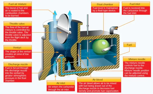
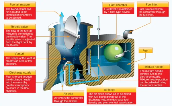
Float Type Carburetor
1. Outside air → air filter → air intake
2. Air flows through venturi → accelerates → creates low pressure area
3. Fuel is drawn from the higher float area through a fuel jet and into the throat
4. Fuel and air mixes → pulled into intake manifold and combustion chamber
5. The fuel/air mixture is then drawn through the intake manifold and into the combustion chambers where it is ignited
The float name comes from a float in the float chamber - as float rises and falls due to fuel level, fuel inlet changes to let fuel in and out
Mixture controls mixture needle, which opens and closes opening at bottom of carburetor
Throttle controls throttle valve, which alters the amount of fuel air mixture
What is manifold pressure?
Measures the pressure downstream of the throttle valve (think fuel/air mixture in a carbureted engine OR just air pressure in a fuel injected engine)
What is the difference about Engine Cylinder #3?
Cylinder 3 does NOT have a fuel primer line because the intake port for that cylinder measures manifold pressure
What are we looking for when we exercise the props?
How do we lean the mixture for best performance?
125 degree RICH (cooler) of peak value (should be below 435 degrees for best service life)
How do we lean the mixture for economy performance?
Lean to peak EGT (should be below 400 degrees for best service life)