Procedure Support Study Guide
 Call Kai
 Learn
 Practice Test
 Spaced Repetition
 Match
 Flashcards
 Knowt Play
1/180

Earn XP
Description and Tags
Medtronic 2026
181 Terms
What are the 3 types of Fluoro Projections?
1) RAO
2) LAO
3) AP - Common home view
What 3 parts can be seen in the RAO fluoro view?
1) Spine on left
2) Sternum on right (Snoopy Face)
3) Elongated view of the heart
What is RAO fluoro projection best used for?
1) Visualize lead slack
2) Crossing the Tricuspid Valve, see CS ostium, divided basal to apical
3) Best for bifurcation (divide something into 2 branches) of the CS branches
What is LAO fluoro projection best used for?
Split to see left and right chambers
1) 4-chamber view
2) Mid Flare - excellent for elongating certain segments of the arteries to check for blockages
What is the typical Access approach looking like?
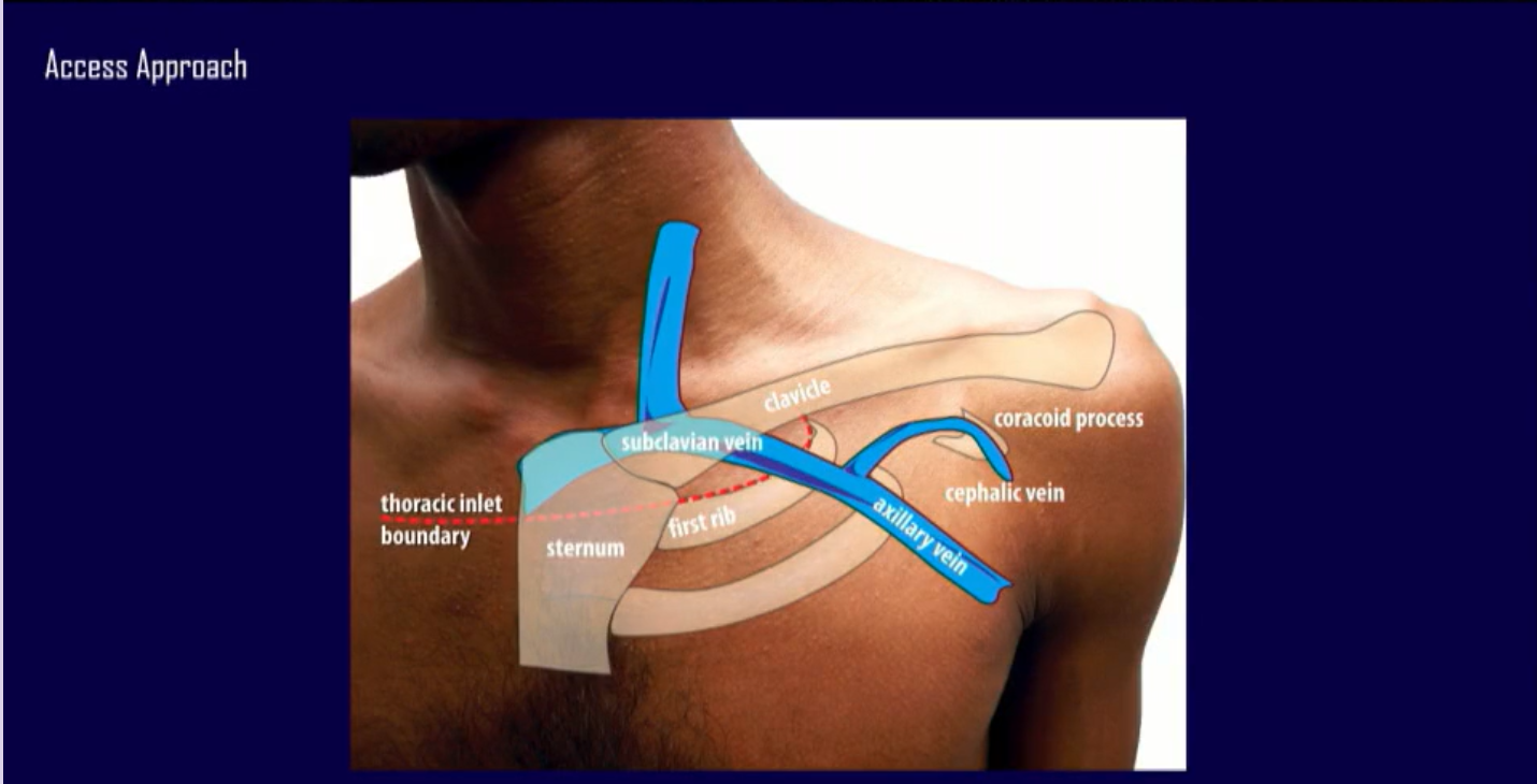
What are the 3 standard venous access methods?
1) Cephalic
2) Axillary
3) Subclavian
What is the method and technique behind cephalic cutdown?
Surgical Cutdown: Isolated in the deltopectoral groove via a direct tissue incision
What are the advantages of Cephalic Cutdown?
Zero risk of pneumothorax
No risk of lead "crush" syndrome
Excellent long-term lead survival
What are the disadvantages of Cephalic Cutdown?
Lower acute success rate (vein may be too small or tortuous)
Time-consuming surgical dissection
Difficult to accommodate multiple leads
What is the method and technique behind axillary venipuncture?
Percutaneous Puncture: Extrathoracic approach, heavily favored with ultrasound guidance.
What are the advantages of Axillary Venipuncture?
Negligible pneumothorax risk (<1%)
Avoids the clavicle-rib lead "crush" zone
High acute procedural success
What are the disadvantages of Axillary Venipuncture?
Technically challenging course without imaging
Requires specialized training (ultrasound/micropuncture)
Risk of inadvertent brachial plexus or arterial injury
What is the method and technique behind subclavian venipuncture?
Percutaneous Puncture: Infraclavicular/intrathoracic approach using anatomic bony landmarks
What is the advantages of Subclavian venipuncture?
Easiest learning curve
Highly predictable anatomy
Fastest procedural times and highest acute access rates
What is the disadvantages of Subclavian venipuncture?
Highest risk of pneumothorax (1–3%)
Risk of "Crush Syndrome" (mechanical lead fracture)
Higher rates of long-term lead insulation failure
What is the introducer size rule?
The Outer Diameter Rule: The external diameter of a sheath is always 1.5 to 2 Fr larger than its internal rating. For example, a 7 Fr sheath has an external diameter closer to 8.5 or 9 Fr
What are the 2 main types of introducer sheath sizes?
6 Fr to 7 Fr Sheaths: Used for standard, single-coil right ventricular (RV) pacing leads or right atrial (RA) leads.
9 Fr Sheaths: Required for thicker leads, such as dual-coil implantable cardioverter-defibrillator (ICD) leads or specialized left ventricular (LV) delivery systems used in cardiac resynchronization therapy (CRT)
What is the Single stick and double wire technique?
This technique is used when two separate leads (e.g., dual-chamber pacemaker) need to be placed through a single venipuncture site.
It is highly effective for reducing puncture risks in the axillary or subclavian veins
What is the advantage of Single-Stick & Double-Wire?
Keeps both wires completely independent throughout the entire procedure.
What is the disadvantage of Single-Stick & Double-Wire?
High-profile sheaths must accommodate two wires simultaneously.
What is the Single stick and retaining 1 guidewire technique?
This is an alternative method to gain dual-lead access from a single stick.
Instead of loading two wires into one sheath at the same time, this technique relies on leaving a wire behind during the lead deployment process.
What is the advantage of Single-Stick & Retaining 1 Wire?
Saves time and equipment; does not require threading two wires into a single sheath hub.
What is the disadvantage of Single-Stick & Retaining 1 Wire?
Risk of inadvertently pulling out the retained wire while peeling the first sheath
What is the Brady Leads and typical numbering scheme?

What are acceptable lead measurements through the analyzer for brady leads?

What is an acceptable placement site for RV passive fix?
A satisfactory position is achieved when the lead tip points straight toward the apex or when the distal end dips or bends slightly
What is an acceptable placement site for RA passive fix?
Generally, a satisfactory position has the lead tip situated against the atrial endocardium in or near the apex of the appendage.
As viewed on fluoroscopy (A-P view), the lead tip points medially and forward toward the left atrium.
A lateral view will show the opening of the J-portion facing the patient’s sternum.
What is an acceptable placement site for RV active fix?
Press the lead tip against the endocardium by gently pushing the stylet and lead at the vein entry site.
While holding the lead connector and ensuring that the stylet is fully inserted, rotate the fixation tool clockwise until the helix electrode is completely exposed.
Maximum helix electrode exposure reveals approximately 1 1/2 to 2 coils of the helix
8-10 turns for helix (make sure not to over-rotate which could damage the lead).
What is an acceptable placement site for RA active fix?
With the lead tip advanced into the atrium and a fully inserted J-shaped stylet in the lead, position the lead tip against the atrial endocardium in or near the apex of the appendage.
With the lead tip against the tissue, rotate the fixation tool clockwise until the helix electrode is completely exposed.
Maximum helix electrode exposure reveals approximately 1 1/2 to 2 coils (see table for maximum number of rotations).
What is the purpose of LAO?
Interventricular Septum profile
Confirms true septal vs. free-wall placement; minimizes perforation risk.
What is the purpose of RAO?
Base-to-apex long axis
Pinpoints longitudinal height (high, mid, low); prevents tricuspid valve impingement.
What is the purpose of AP?
Standard frontal view
Initial anatomical tracking and general macro-navigation of the lead wire.
What is the purpose of Caudal Tilt?
First rib & lung boundaries
Guides safe venous access; significantly lowers pneumothorax rates.
What is Brady helix extension look like?
Brady-Breaks
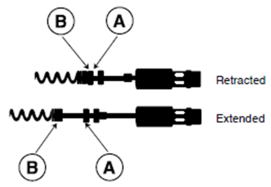
What is the Tachy Leads and typical numbering scheme?

What is Tachy helix extension look like?

What are acceptable lead measurements through the analyzer for tachy leads?

What is an acceptable placement site for RV leads?
Right Ventricular Interventricular Septum (IVS)
If direct conduction system pacing cannot be achieved or is not indicated, the interventricular septum is the preferred alternative to apex pacing.
Mid-Septum: The lead is placed along the thick middle section of the wall separating the two ventricles. Mid-septal pacing provides a narrower, more efficient QRS complex than apical pacing and features a very low risk of cardiac perforation.
Right Ventricular Outflow Tract (RVOT) Septum: Positioned in the upper region of the septum closer to the pulmonary valve. Care must be taken using fluoroscopy (especially the LAO view) to ensure the lead is truly on the thick septal wall and not on the free wall.
Apex is NOT preferred because it come lead to further heart failure
What is the flow for an appropriate DFT preparation?
Before inducing ventricular fibrillation (VF) to establish the DFT, specific system preparations must occur via the Medtronic ICD Programmer:
Programmer Changes: Make sure 2 shocks are prepped, reduced detection window (NID 12/16), increased sensitivity to 1.20 mV, run wavelet, and Turn ON the therapies
Confirm Induction Method and Procedure: Confirm which induction method will be used (50 Hz Burst or T-shock) and that all staff are ready.
Backup External Defibrillation: Pads must be placed on the patient, and a fully functional external defibrillator must be armed and ready as a primary safety redundancy.
What is an acceptable safety margin for DFT programming?
≥ 10 Joules below the maximum output of the device
A test shock is typically set to 14 Joules or 15 Joules below max output. Success at this level implicitly guarantees an acceptable safety margin.
What are some troubleshooting steps when it comes to DFT testing?
If a patient fails a safety margin protocol (i.e., the device fails to defibrillate at a level ≥10J below its maximum), non-invasive programming changes should be trialed before surgical revision:
Polarity Reversal: Toggle the active vector between standard (Anode to RV coil, Cathode to Can/SVC) and reversed configurations.
Waveform Tilt Adjustment: Optimize the biphasic pulse width settings via the Medtronic programmable parameters to balance the voltage delivery.
Vector Shifting: Program the Superior Vena Cava (SVC) coil ON or OFF to re-route the electrical field across a larger mass of the myocardium
What are DF1 and DF4 header configurations for Tachy devices?

What are single coil vs dual coil Defib lead considerations?
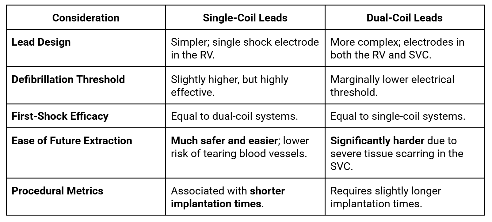
When is a Dual-Coil Lead Still Considered?
1) Patients with very high defibrillation thresholds or unique body habitus (e.g., severe obesity) where changing the shock vector is needed to successfully stop an arrhythmia.
2) Individuals undergoing secondary prevention who have already survived a cardiac arrest and have demonstrated a specific clinical requirement for lower shock energy configurations
What does it mean to delivering manual therapy through the device and what happens?
1. Manual Induction of an Arrhythmia (Testing)
Before delivering manual therapy to stop a rhythm, doctors often have to manually start one to test the device.
What happens: The physician uses the programmer to command the ICD to deliver an ultra-rapid burst of pacing (or a small, timed electrical T-wave shock).
The result: This safely and intentionally triggers a temporary episode of Ventricular Tachycardia (VT) or Ventricular Fibrillation (VF). This allows the team to ensure the device correctly "sees" the lethal rhythm and that the leads are working perfectly.
What are True bipolar vs integrated bipolar programming look like?

What are the clinical implication and danger of oversensing for ICDs?
Because an integrated bipolar system uses the large RV shocking coil to listen to the heart, it acts like a much larger antenna.
This makes it prone to oversensing electrical noise from outside sources or nearby muscles (like the diaphragm or pectoral muscles).
If the device misinterprets this muscle noise as a rapid, lethal heart rhythm (like VF), it can result in the patient receiving an inappropriate and painful shock while completely awake.
True bipolar programming heavily limits this risk by keeping the listening zone small and hyper-localized to the heart tip.
What are RV/SCV acceptable impedance measurements?
RV Coil-to-Can (Single Coil Pathway): 30 to 110 Ohms ( Ω )
Clinical Context: Because a single-coil configuration has a smaller overall surface area than a dual-coil layout, its baseline resistance is inherently higher. Values between 50 Ω and 80 Ω are considered highly typical and optimal.
SVC Coil-to-Can or Dual-Coil Pathway (RV + SVC to Can): 20 to 70 Ohms ( Ω )
Clinical Context: Activating both the RV and SVC coils in parallel creates a much larger surface area. This drops electrical resistance, meaning a healthy dual-coil system should output lower impedance values than a single-coil system
What is the VTOP and acceptable charge time or longevity gauge at initial implant for Pre-Viva device and current devices?
Pre-Viva Devices (Legacy Platforms):
Acceptable Baseline: 7 to 11 seconds.
Context: Older lithium-silver vanadium oxide (Li-SVO) batteries required a slightly longer ramp-up time.
An initial charge time exceeding 12 to 14 seconds at the time of implant would signal a defective battery cell or a deformed capacitor.
Viva and Current Generation Devices (Cobalt / Crome / Evera):
Acceptable Baseline: 6 to 9 seconds.
Context: Modern Medtronic devices utilize optimized battery chemistries and advanced hybrid capacitors.
At initial implant, a clean device will typically complete a full 35J–40J charge rapidly. Any initial implant charge time approaching >10 seconds is abnormal for a brand-new contemporary generator
What are the 4 types of induction methods for Tachy devices?

What are the programmable settings for T-shock?
Drive Cycle Length (V-Drive): The pacing rate (usually 8 beats at a cycle length of 400ms to 500ms) used to steady the heart rhythm right before the shock.
Coupling Interval (T-S1): The exact delay (in milliseconds) between the last paced beat and the delivered shock. This is meticulously calculated to land exactly on the T-wave.
Shock Energy: The strength of the induction shock, typically programmed between 0.4 Joules and 2.0 Joules.
What are the programmable settings for Burst pacing?
Burst Cycle Length: The time interval between each pacing pulse. For VT induction, it is typically programmed between 200ms and 300ms (equivalent to 200–300 beats per minute).
Number of Pulses (Train Length): The total number of rapid pacing beats delivered in a single burst, usually programmed to 8 to 15 pulses
What are the programmable settings for Programmed Electrical Stimulation (PES) / Premature Ventricular Extrastimuli?
Drive Train (S1-S1): A sequence of 8 pacing beats delivered at a fixed cycle length (e.g., 600ms or 400ms).
Extrastimuli (S2, S3, S4): The number of premature beats introduced after the drive train. Clinicians usually start with one (S2) and progress up to three or four premature beats if the rhythm does not induce initially.
Coupling Intervals (S1-S2, S2-S3): The precise intervals (in milliseconds) for the premature beats. These are progressively shortened ("decremented") by 10ms to 20ms during testing to find the heart's exact vulnerable window
What are the programmable settings for 50 Hz Burst induction?
Duration: The length of time the 50 Hz burst is held down, typically programmed between 1.0 and 5.0 seconds.
Note on operation: Unlike other methods, this acts strictly as a manual hold feature on the programmer dashboard. The moment the clinician lifts their finger off the touchscreen button, the burst instantly stops.
How does one determine if detection and therapies are ON?
The Status Line (Top of the Screen): Medtronic programmers display a global status text bar running across the top margin of the software interface.
If tachy therapies are active, it will display "Tachy Detection ON".
If therapies are globally deactivated, this text changes to a bold, highly visible "Tachy Detection OFF" or "Therapies Disabled".
The Parameters (Params) Screen: By navigating into the Params icon -> Detection section, you will see a global operational toggle. Medtronic devices allow you to set this parameter to three states:
On: Both automatic rate tracking (detection) and automatic delivery of shock/ATP treatments are fully live.
What are some anatomical structures that can make CS cannulation more difficult?
Thebesian Valve (Valve of the Coronary Sinus):
This is the most common anatomical culprit for cannulation difficulty, present in 70% to 82% of human hearts. It is an embryonic remnant located at the inferomedial border of the CS ostium.
The valve varies dramatically in shape and can be fibrous, fenestrated, or completely occlusive (covering the entire ostium), preventing a guidewire or sheath from entering.
Eustachian Valve and Eustachian Ridge:
The Eustachian valve sits at the junction of the inferior vena cava (IVC) and the right atrium.
A prominent, hyperplastic Eustachian valve or a thick, muscular Eustachian ridge can act as a physical barrier.
When approaching from a superior vector (subclavian or axillary vein), the catheter sheath often gets caught on this ridge, deflecting the wire away from the CS ostium and down toward the tricuspid valve or RV

What are some additional anatomical structures that can make CS access difficult?
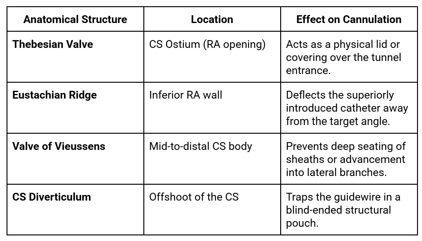
What anatomical structures are present for CS access?

What are the CS command catheter specs?
Tapered Distal Shaft: The transition from a 9.0 Fr proximal shaft to an 8.5 Fr distal profile minimizes trauma during deep seating into the coronary sinus.
Hydrophilic Coating: Applied to the distal outer portion of the shaft to maximize lubricity, reduce friction against vessel walls, and ease deep seating.
Integrated SureValve: A built-in hemostasis valve that eliminates the need for separate external bulky valves, streamlining the implant procedure and reducing lead management length constraints.
Torque Control: Engineered braided core infrastructure provides a high 1:1 torque response from the proximal handle to the shaped distal tip

What are the 2 pre-packaged CS catheter kits?
Curved Kit (Model 6250VC / 6250VIC):
Contains an Extended Hook (EH) catheter and a Multipurpose Bend 2 (MB2) catheter.
Straight Kit (Model 6250VS / 6250VIS):
Includes the straight-profile 45 cm and 50 cm catheter variations
What are the 3 general categories when it comes to CS catheters?
Straight Profiles: Available lengths include 45 cm, 50 cm, and 57.5 cm (e.g., 6250VI-45S, 6250VI-50S, 6250VI-57S).
Multipurpose Curves: MB2, MB2X, MP, MPX, and MPR variants (ideal for standard CRT lead positioning).
Anatomical Bends: Extended Hook (EH), Extra Extended Hook (EXHL), Amplatz (AM), and specialized 3-D right-sided configurations (6250D)
Which command catheter is used for which anatomy?
1) Multipurpose Bends: Normal/standard anatomy
MB2, MP
2) Extended Hook: Enlarged Right Atrium
EH, EXHL
3) Amplatz Type: High or Posterior CS Take-off
AM (aggressive secondary curve)
4) Extra-Reach / Expanded Curves: Severe Cardiomegaly (highly dilated)
MB2X, MPX
5) 3-D Right Sided: Right-Sided Implants / Anomalous Anatomy
6250D
6) Straight Profiles: Custom Contouring / Telescoping
45S, 50S, 57S
How does one manage “Difficult” or Tortuous Anatomy?
1. Outer Sheath: A larger Attain Command shape (e.g., EH or MB2) is used to navigate the right atrium and sit securely at the entrance of the CS ostium.
2. Inner Sub-Selection: The Attain Select™ II sub-selection catheter (5.7 Fr) is advanced inside the outer catheter. It features independent 90° or 130° angled soft tips that can be rotated to negotiate tortuous side branches and push past anatomical blockages without traumatizing the vessel walls.
3. Alternatively — Steerable Deflectable Options: For highly unpredictable anatomies, physicians bypass fixed shapes entirely and use the Attain™ Deflectable Catheter System (Model 6227DEF), which uses an integrated handle mechanism to manually flex or straighten the curve on-the-fly inside the heart.
What are the Attain Select II specifications – regular vs petite and lead delivery through the sub-selector?
The only operational difference is the working length and corresponding curve tip geometry profiles.
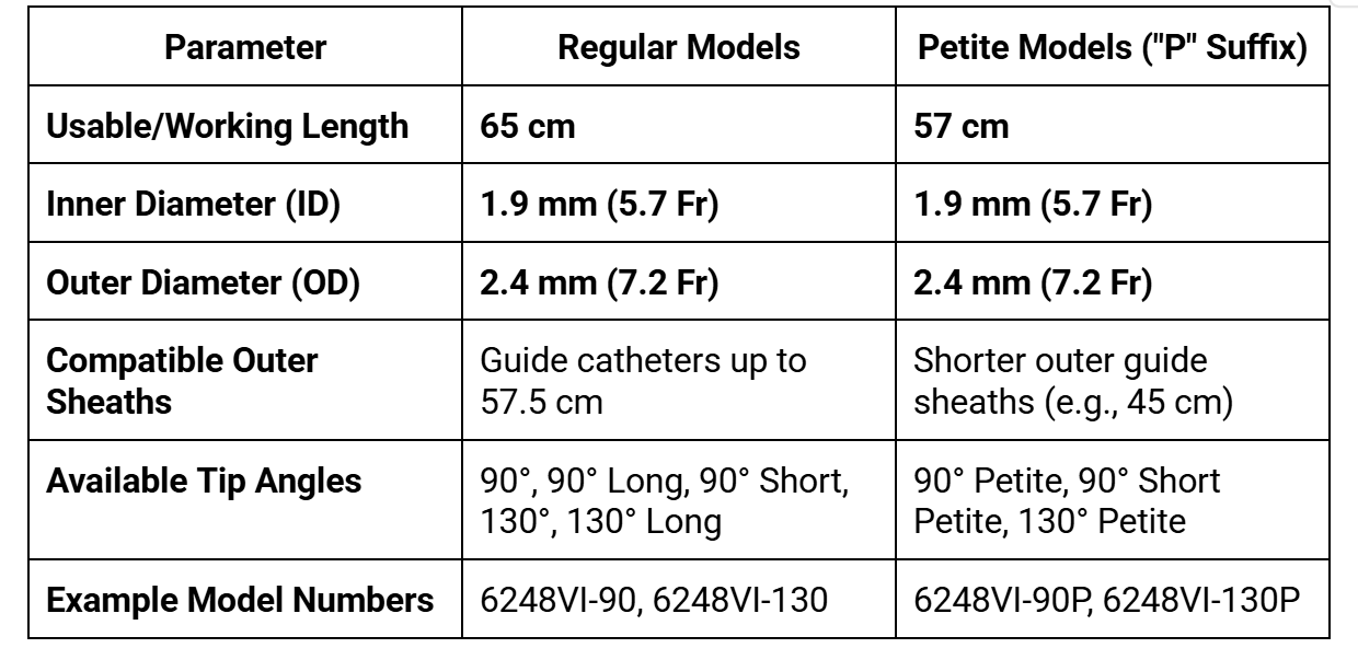
What are the techniques and steps for CS cannulation?
0.035 wire, Catheter, Sub-selector, 0.014 wire and lead
Advance to the Ventricle: Advance the outer sheath and its inner braided core as a single unit over a standard guidewire through the superior vena cava (SVC) and across the tricuspid valve into the Right Ventricle (RV).
Apply Torque: Align the C-arm fluoroscopy machine into the RAO 30° or LAO 30° view. Apply a steady counterclockwise torque to the catheter hub to rotate the tip posteriorly toward the interventricular septum.
Withdraw and Drop: Slowly pull the catheter unit backward out of the RV. As the tip slips back across the tricuspid annulus into the right atrium, the counterclockwise tension will cause the tip to visibly "drop" posteriorly into the CS ostium.
Puff and Confirm: Inject a small "puff" of full-strength contrast medium through the manifold to verify the tip is engaged within the CS and not caught in a right atrial trabeculation or the coronary sinus valve (Thebesian valve).
Deep Seating: Advance a soft-tipped angled glide wire (or an Attain Select™ II subselection catheter) deeply into the main body of the CS to act as a stabilizing anchor. Track the outer delivery sheath forward over it to secure deep placement.
What are Steps for Verifying True Coronary Sinus Access?
No PVCs will occur when access is obtained
Step 1: Tactile and Mechanical Resistance
Step 2: Fluoroscopic Visual Anchors
Step 3: Contrast Injection ("Puffing")

What are key anatomical features when it comes to identifying LV anatomy?
Great Cardiac Vein (GCV) / Anterior Interventricular Vein (AIV): Tracks anteriorly along the anterior interventricular groove.
It is generally avoided for CRT because pacing here does not correct the typical left bundle branch block (LBBB) delay, and it runs close to the left anterior descending (LAD) artery.
Lateral / Anterolateral Veins: Branch off the mid-to-high portion of the CS.
These are highly desirable target zones if they originate far enough away from the anterior wall.
Posterolateral (PL) Veins: Typically the gold standard / ideal target zone for CRT.
Pacing here targets the latest area of mechanical contraction in a typical failing heart (the basolateral/posterolateral segment), leading to the highest rate of patient response.
Posterior Vein / Middle Cardiac Vein (MCV): Runs along the inferior/diaphragmatic surface of the heart.
While large and easy to cannulate, it is generally a suboptimal pacing site unless no other lateral options exist.
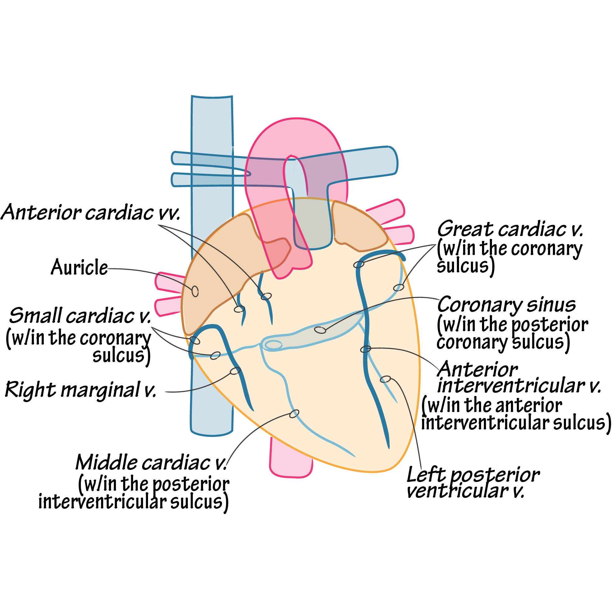
What are some key ways of Identifying Anatomy Using Fluoroscopic Projections for LV access?
A. Right Anterior Oblique (RAO 30°) – The "Clock" View
12 o'clock to 2 o'clock: Great Cardiac Vein (Anterior)
3 o'clock to 4 o'clock: Anterolateral / Lateral Veins
5 o'clock to 6 o'clock: Posterolateral Veins (Target Zone)
7 o'clock to 8 o'clock: Posterior / Middle Cardiac Vein (Inferior)

What are key specifications for the 6215 Balloon Catheter?

What are the Fluoroscopy views and advantages of each pertaining to the CS lead placement?

What are key characteristics and features of LV leads?
Quadripolar Technology (IS4 Compatibility): 16 vectors for pacing
Steroid Elution
Fixation Mechanisms (passive vs active)
MRI Compatibility
What are the technical specifications of LV leads?

What are the 5 package contents of LV leads?
The LV Lead: The pre-shaped transvenous pacing lead, pre-loaded with a shipping stylet.
Stylet Accessory Kit: A complete portfolio of straight and custom-tapered/curved stylets of varying stiffness (e.g., light, medium, firm) to aid in pushing and steering the lead.
Veneer/Guidewire Guideline Components: Slitting tools or protective sleeves to manage the transition over 0.014-inch guidewires (Over-The-Wire / OTW delivery). [1]
Torque Guide / Tool: A plastic torque grip device that clamps onto the lead or wire to facilitate precise handling.
Technical Manual & Documentation: Comprehensive instruction manual, MRI screening guidelines, and stick-on device registration tracking labels for the patient chart.
Which LV leads are used for which types of branches (or anatomies)?

What are 4798 LV lead use?
The Model 4798 is a specialized active-fixation quadripolar LV lead designed to address the most common failure mechanism in CRT: post-operative lead dislodgement from broad, roomy veins.
Fixation Mechanism: An electrically inactive side helix positioned between pacing electrodes 3 and 4.
Active Engagement: Once satisfied with the pacing position, the operator holds the inner wire steady and rotates the proximal lead body clockwise.
This rotation coils the side helix directly into the endothelial layer of the venous wall, locking it in place.

What is the largest guidewire diameter LV leads will accept?
maximum guidewire diameter of 0.014 to 0.018
What are Medtronic hybrid wire characteristics?
The defining characteristic of the Attain Hybrid wire is that it combines the structural stability of an inner lead stylet with the structural agility and tracking of a standard coronary guidewire into a single instrument
Stylet-Like Pushability
Guidewire-Like Steerability
Cant-Straightening Interaction

What are the LV pacing configurations for bipolar leads?
A bipolar LV lead features only two physical electrodes at its distal end: the Tip (LV1) and the Ring (LV2). This layout provides only 2 standard programming combinations for pacing:
LV Tip to LV Ring (True Bipolar): Pacing current flows from the distal tip electrode directly to the proximal ring electrode on the lead body. This concentrates the electrical vector entirely within the local target vein.
LV Tip to RV Coil / Can (Unipolar/Extended Bipolar): Current travels from the LV tip electrode across the left ventricle to either the Right Ventricular (RV) shocking coil or the titanium device casing (the generator/can) in the pectoral pocket.
⚠ The Bipolar Constraint: If the LV tip happens to sit directly over the phrenic nerve or in a zone of high scar tissue (scarred myocardium with high pacing thresholds), the physician has almost no options to correct it electrically and must physically pull and reposition the lead.
What are the LV pacing configurations for quadripolar leads?
A quadripolar lead features four distinct electrodes along its distal tip, labeled sequentially from distal to proximal: Distal 1 (D1), Mid 2 (M2), Mid 3 (M3), Proximal 4 (P4).
16 pacing vectors
Multi-Point Pacing (MPP) / Dual-Site Pacing
Advanced quadripolar CRT devices allow the generator to fire two separate LV pulses sequentially from different electrodes during a single heartbeat (e.g., firing D1 to M2, followed immediately by M3 to RV Coil).
What are the 2 biggest advantages of quadripolar LV leads?
Bypassing Phrenic Nerve Stimulation (PNS): If a patient experiences diaphragmatic twitching when pacing from electrode M2 because it lies near the phrenic nerve, the clinician simply flips a software switch to pace from D1 or P4.
This shifts the electrical field away from the nerve, eliminating the twitch instantly.
Managing High Thresholds (Battery Drainage): If a specific electrode rests on ischemic scar tissue, it will require a massive, battery-draining voltage to capture the heart.
The clinician can electronically scan all 16 vectors in seconds to find an alternative electrode sitting over healthy tissue with a low pacing threshold, safely preserving the device's battery life.
What are Testing methods, recommendations and troubleshooting for LV quadripolar leads?
1) Scenario A: High Pacing Thresholds Across All Distal Vectors (D1 and M2)
The Recommendation: Electronically shift the primary pacing site to the more proximal electrodes (M3 to RV Coil or P4 to M3).
Because proximal electrodes sit further back in the main branch of the vein, they often maintain contact with healthy, non-infarcted tissue.
2) Scenario B: Sudden High Impedance (>2,000 Ohms) on a Single Vector
The Recommendation: Program the device to completely bypass that faulty electrode. For instance, if M2 is broken, shift the programming from D1 to M2 over to D1 to M3 or D1 to RV Coil.
This restores full CRT functionality without subjecting the patient to a surgical lead extraction.
3) Scenario C: Intolerable Late-Onset Phrenic Nerve Stimulation (PNS)
The Recommendation: Activate automated algorithms such as Medtronic's Attain Capture Management™ (ACM).
Software automatically tracks pacing thresholds daily and can be set to shift the pacing vector autonomously if it detects that the safety margin has become too narrow, protecting the patient from experiencing continuous muscle twitching at home.
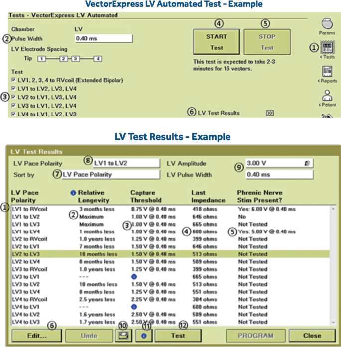
What does the Vector Express function do?
1. Impedance Sweep: It measures the electrical resistance (in ohms) for all available quadripolar pacing pathways to immediately verify structural lead integrity.
2. Threshold Search: The algorithm performs rapid, localized voltage down-titrations for every vector to pinpoint the exact pacing capture threshold (the lowest voltage required to depolarize the LV myocardium).
3. Longevity Estimation: Utilizing the raw capture thresholds and recorded impedances, the software dynamically calculates the projected battery consumption for each vector.
4. Summary Matrix Generation: It organizes the massive collection of data points into a clear, color-coded visual matrix on the programmer screen.
What is the biggest benefit of Vector express?
1. Dramatic Time Savings & Efficiency
2. Non-Invasive Management of Phrenic Nerve Stimulation (PNS)
3. Maximized Device Battery Longevity
4. Automated Troubleshooting of Lead Complications
What are the key components needed for the LV CRT removal process?
The Medtronic Slitting Tool: A specialized plastic handle housing an internal razor blade designed to snap cleanly over the catheter shaft.
Hemostatic Forceps (Peans or Mosquitos): Used to firmly grasp and stabilize the guide wire or lead body.
Live Fluoroscopy: Vital to visually track the lead tip throughout the entire peeling process
What is the The "Push-Pull" Slitting Technique when slitting the LV lead?
The Stabilizing Hand: Firmly pin the proximal end of the LV lead body (and inner wire) completely stationary relative to the patient's chest. This hand must not move.
The Moving Hand: Grasp the slitting tool and pull the catheter shaft backward through the blade in a continuous, smooth motion. As the blade cuts open the polymer wall, peel the two severed halves of the catheter outward and away from the lead.
Continuous Fluoroscopic Monitoring: The operator or an assistant must look at the fluoroscopy screen to verify that the distal tip of the LV lead is remaining completely frozen in the target branch. If the lead tip begins to back out even a millimeter, stop slitting immediately, re-advance the sheath to stabilize it, and adjust your traction.
What is the step-by-step removal process for an LV lead?
Step 1: Secure the Lead and Guidewire
Step 2: Retract the Inner Sub-Selector (If Applicable)
Step 3: Align and Mount the Slitting Tool
Step 4: The "Push-Pull" Slitting Technique
Step 5: Final Slit Through the Valve Handle
Step 6: Final Lead Stabilization and Wire Extraction
What are some Critical Clinical Precautions when removing the LV CRT catheters?
Avoid Blade Contact with the Lead: Keep the lead body pulled taut and perfectly centered inside the catheter lumen while slitting. If the catheter twists during peeling, the razor blade can accidentally slice into the polyurethane insulation of the lead, ruining its electrical integrity.
Maintain Hemostasis: Because slitting opens a direct pathway to the venous system, ensure the pocket is compressed or a finger is placed gently over the venous entry site to minimize blood loss and prevent an air embolism.
What are the DF1 and DF4 CRT Header configurations?

What are some ways to identify PNS (Phrenic Nerve Stimulation)?
Diaphragmatic Twitching: The patient experiences a rhythmic, involuntary hiccup-like contraction of the diaphragm or abdomen that matches the programmed pacing rate of the device.
Postural Dependency: PNS is highly dynamic.
A patient may have zero twitching while lying flat on the operating table, but experience severe twitching when sitting up, turning onto their left side, or breathing deeply as the heart shifts closer to the nerve.
Patient Discomfort: While not physically dangerous, chronic diaphragmatic twitching is highly irritating, can disrupt sleep, and frequently causes anxiety.
How can one test for possible PNS during a CRT implant?
Before removing the delivery sheaths, the operator paces the lead at high voltages (10.0 V) across all electrodes while physically palpating the patient’s left upper abdomen to check for contractions (test for Max output on analyzer).
What are some options to resolve PNS (after an implant)?
Option A: Electronic Vector Reprogramming (Primary Solution)
Option B: Utilizing Medtronic Attain Capture Management™ (ACM)
Option C: Adjusting Pulse Width and Output Delays
Option D: Physical Lead Repositioning (Last Resort)
What are C304-HIS and C315-HIS catheter specifications and characteristics?

What is the C315-HIS catheter best used for?
The C315-HIS features a pre-shaped, fixed curve matrix explicitly molded to sit against the tricuspid valve annulus from a standard superior venous entry (e.g., left cephalic/subclavian).
The Workflow Benefit: Because it uses an integrated in-line valve, it is very streamlined. It does not require assembling external valve accessories on the sterile field.
Anatomic Constraint: It works exceptionally well in standard, non-dilated hearts. However, because the shape cannot be altered on-the-fly, if the patient's right atrium is physically enlarged, the pre-shaped curve may "fall short" or float freely in the atrium, failing to back up against the septum to provide support for lead screw advancement.

What is the C304-HIS catheter best used for?
The C304-HIS is an advanced steerable guide catheter with an out-of-plane proximal curve managed by a tension-handle dial.
The Workflow Benefit: By dialing torque or tension on the handle, operators can manually expand or contract the curve reach inside the heart. This mechanical adjustability allows the tip to approach the His-bundle region at an angle closer to completely perpendicular, resulting in a significantly higher initial fixation and lead penetration success rate.
Challenging Atria: It is specifically indicated for patients with severe cardiomegaly or dilated right atria (RA volumes measuring between 110 mL and 139 mL) where fixed sheaths cannot make physical contact with the tissue.
Structure: It has a larger body profile (8.4 Fr requiring a 9 Fr introducer) and utilizes two highly distinct gold marker bands to track the deflection point under live fluoroscopy

What are the 3830 lead characteristics and specifications?
Because it is lumenless, it does not contain an internal hollow channel for a stylet. Instead, it is a solid, ultra-slim cable that relies entirely on a specialized guide catheter (like the C315-HIS or C304-HIS) for delivery, torque transmission, and mechanical support.

What are the key features to look for when pre-fixation of LBB on a 12-Lead ECG?
Lead V1: Wide "W" Pattern / Notch at the Nadir.
Lead V1 demonstrates a classic Left Bundle Branch Block (LBBB) morphology with a wide, entirely negative QS complex. Crucially, a distinct notch or "W" shape is visible right at the bottom (nadir) of the QS wave.
This indicates that pacing is originating from the middle of the right ventricular septum.
Leads II, III, and aVF (Inferior Leads): Positive Deflections.
The QRS complexes in the inferior leads are strongly positive (upright). This confirms that the lead is positioned high enough on the septum—close to the His-bundle/tricuspid valve plane—causing the electrical wavefront to propagate downward toward the apex.
Leads I and aVL: Positive/Upright.
A completely positive QRS complex in lead I confirms that the electrical axis is moving from right to left, aligning with a proper septal entry point.

What is the Clinical Relevance of the "W" Notch in V1?
The physical location of the "W" notch in lead V1 serves as an electronic map for the operator to fine-tune the lead position along the septum before screwing it in:
Notch at the Nadir (Exact Middle): Indicates an ideal position. The lead is perfectly situated in the mid-septum, directly over the pathway of the left bundle branch trunk.
Notch on the Down-slope: Indicates the lead tip is positioned too high (closer to the basal septum / His area).
Notch on the Up-slope: Indicates the lead tip is positioned too low (closer to the cardiac apex).
What are Dynamic Changes Expected After Fixation?
1. As the Lead Drills Deep: As the 3830 penetrates the muscular interventricular septum, the "W" notch in lead V1 will physically climb up the up-slope of the QRS complex.
2. Upon Left Conduction System Capture: The moment the lead tip exits the left septal endocardium and captures the Left Bundle Branch, the morphology changes completely. Lead V1 flips from an LBBB pattern to a Right Bundle Branch Block (RBBB) pattern (manifesting as a terminal R-wave or an qR/rsR' pattern), confirming successful conduction system engagement.
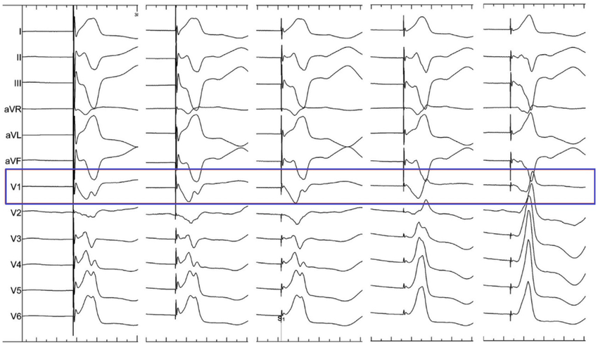
What is the The Morphologic Shift in Lead V1 (The Primary Indicator) show?
As the lead penetrates from the right ventricular (RV) side toward the left ventricular (LV) side of the septum, the paced QRS morphology in lead V1 undergoes a predictable, highly visible transition:
The Baseline (RV Septum): Starts as a wide, completely negative Left Bundle Branch Block (LBBB) pattern with a deep QS wave containing a "W" shaped notch at the nadir.
The Septal Advance (Transition phase): As the lead bores deeper, the "W" notch physically shifts to the right, climbing up the upward slope of the QS complex.
The overall duration of the QRS complex begins to progressively narrow.
LBB Capture (The Target Terminal R-Wave): The moment the lead tip engages the left-sided conduction tissue, lead V1 transitions to a Right Bundle Branch Block (RBBB) pattern.
This is marked by the appearance of a terminal R-wave, displaying a qR, rsR', or M-shaped pattern in V1.
This terminal R-wave is the signature indicator that the electrical impulse is now traveling instantly down the left bundle branch.

What is the Lead II show for LBB pacing?
Lead II Discordance: The polarity of Lead II should be observed.
A highly positive (upright) Lead II indicates a basal/mid-septal trajectory.
If Lead II becomes deeply negative, it warns the operator that the catheter has slipped inferiorly or apically.