Hway Finals
 Call Kai
 Learn
Learn Practice Test
 Spaced Repetition
 Match
Match Flashcards
 Knowt Play
1/224

There's no tags or description
Looks like no tags are added yet.
Name | Mastery | Learn | Test | Matching | Spaced | Call with Kai | Chat |
|---|
No analytics yet
Send a link to your students to track their progress
225 Terms
Highway Design
Geometric + Structural
AASHTO
(American Association of State Highway and Transportation Officials) is an organization that develops standards and guidelines for highway design and transportation practices.
CONSISTENCY
THE MOST IMPORTANT SINGLE RULE IN HIGHWAY DESIGN
BASIC CONSIDERATIONS ON GEOMETRIC DESIGN OF HIGHWAYS
Must be suitable for the traffic volume
Must be consistent and mist avoid surprise changes in alignment, grade and distance
Must be pleasing to the user and those who live along with it
Must be complete
Should be as simple as possible from the standpoint of the builder
Should be maintained at the least cost
Must be safe
ROAD NETWORK
Composed of various types of roads, each of which performs a particular service in facilitating vehicular travel between points of trip origin and destination.
CONSIDERATION FOR CLASSIFICATION
Legal control
urface type
Function
Geometric elements
Location
Traffic volume
Urban Roads
Principal arterial / freeways / expressway
Minor arterial
Collector street
Local street
Rural Roads
Principal arterial / freeways / expressway
Major arterial
Minor arterial
Collector street
Local street
Freeways
Through movement exclusively
Surface Arterials
Through movement primary and some live access
Collectors
Traffic movement to higher rank roads, access to abutting properties
Local Roads
Access to abutting land and local traffic movement
PHILIPPINE ROAD SYSTEM
National road
Provincial road
City road
Municipal road
Barangay road
Tourism road
Farm to market road
HIGHWAY CAPACITY
Maximum number of vehicles that are reasonably expected to pass a given point over a given number of time
Measured in terms of number of vehicles per hour (veh/hr)
As. the volume of traffic approaches capacity, the average speed is markedly reduced
Depends on the average length of vehicles and the average spacing of moving vehicles which depends on the reaction time of the drive
2.5 SECONDS
PERCEPTION TIME + REACTION TIME
REACTION TIME
period of time that elapsed before muscular reaction occurs
PERCEPTION TIME
interval of time required before reaction begins
DESIGN HOURLY VOLUME (DHV) / OBSERVED TRAFFIC VOLUME
Projected hourly volume that is used for design Percentage of the expected ADT on the highway The traffic volume to be used is the 30th highest hourly volume
DHV as recommended by AASHTO
• Rural roads – 15%
• Recreational roads – 35%
• Urban roads – 8%
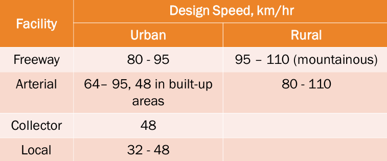
DESIGN SPEED
The speed determined for design and correlation of the physical feature of a highway that influences vehicles operation
It is the maximum speed that can be maintained over a specified section of the highway when weather and traffic conditions are so favorable that the design features (tightness and super elevation of curves, sight distance, and grade) of the highway govern
Selected to achieve a desired level of operation and safety on the highway
Minimum Recommended Design Speed
TYPES OF TERRAIN
Level
Rolling
Mountainous
Level
•Relatively flat
•Horizontal and vertical sight distance are generally long and can be achieved without much construction difficulty or major expenses
Rolling
•Natural slopes that often rise above and fall below the highway grade with occasional steep slopes that restrict the normal vertical and horizontal alignments
Mountainous
•Sudden changes in ground elevation in both the longitude and transverse directions
•Requires hillside excavations to achieve acceptable horizontal and vertical alignment
DESIGN VEHICLE
Selected to represent all vehicles on the highway (weight, dimensions, operating characteristics)
Used to determine critical design features such as radii at intersections and turning roadways as well as highway grades
Passenger cars, trucks, trailers, buses, motorcycles, etc
PASSENGER CARS
When parking lots are the main traffic generators,
SINGLE UNIT TRUCK
Design of intersections at local streets and park roads,
CITY TRANSIT BUS
At intersections of state highways and city streets that serve buses with relatively few large trucks,
84 PASSENGER LARGE SCHOOL BUS (12m) or 65-PASSENGER CONVENTIONAL BUS (11m)
At intersections of highways and low-volume county highways or township or local roads with less that 400 ADT,
Principal Elements of Cross Section Elements
•Pavement
•Travel lanes
•Shoulders
•Median
Marginal Elements of Cross Section Elements
•Curbs
•Sidewalks
•Drainage channels and side slopes
•Traffic barriers
•Frontage roads
•Noise control
•Roadside control
•Pedestrian crossings
•Curb-cut ramps
•Bicycle facilities
•Bus turn outs
•Park and ride facilities
PAVEMENT
Running Surface
Traffic Lane
portion of the pavement allotted for the use of single line of vehicles
TYPES OF PAVEMENT SURFACES
• High
• Intermediate
• Low
CROSS SLOPE
slope of the surface of a pavement measured at right angles to the horizontal alignment
Steeper slope are strongly recommended to flow rainwater away more rapidly reducing the water thickness on the road pavement
Factors considered in specifying the number of lanes:
Traffic density
Highway capacity
Average daily traffic (ADT)
Percentage of truck or bus traffic to use the highway
TRAFFIC LANE / TRAVEL LANE
Widths usually vary from 2.7m to 3.6m
3 or 3.3m –on 2-lane, 2-way rural roads / low speed facilities
2.7m on low traffic urban areas with extreme right-of-way concerns
DESIRABLE WIDTH IS 3.65 meters.
All roads should be designed to accommodate trucks, buses and passenger cars with safety and convenience
Minimum width of traffic lane depends upon the width of the design vehicle and upon the lateral clearance between passing vehicles and clearances from abutments or overpasses or from curbs and gutter
CHARACTERISTICS OF SHOULDER
Graded
Surfaced
Usable
Minimum Width – 1.0 m (DPWH Manual)
Minimum width of 1.5 m for AADT greater than 1250
No difference in elevation between surface of the shoulder and the surface of the pavement
FUNCTIONS OF A SHOULDER
1. Structural support to pavement
2. Space for pedestrian and bicycle use
3. Space for vehicles with mechanical difficulties
4. Space for motorists to stop occasionally to consult road maps
5. Space for evasive maneuvers
6. Improved sight distances
7. Improved highway capacity
8. Lateral clearance for signs and guardrails
9. Stormwater discharge further from the travelled way
10.Sense of openness
MEDIAN
SECTION OF A DIVIDED HIGHWAY THAT SEPARATES THE LANES IN OPPOSING DIRECTIONS
FUNCTIONS OF MEDIAN
To separate opposing traffic streams
To prevent U-turn and enhance the safety to traffic flow Makes turning of vehicles smooth and safe operation
To provide space to install traffic signs or other traffic managing facilities
To provide storage lane for left turn vehicles at the intersections
To provide a haven in case of emergency
To minimize headlight glare in night time
Reduces conflicts and accidents between opposing streams of traffic
WIDTH OF MEDIAN
SHOULD BE AS WIDE AS POSSIBLE
Minimum width is from 4ft (1.22m) to 60ft (13.3 m)
Rural section of freeway: 18.0 to 27.0m
Suburban or mountainous: 3.0 to 9.0m
Rural and urban arterials: >18.0m
6 to 18m allow drivers to cross each roadway separately
4.20 to 6.60m provides protection for turning vehicles
1.20 to 1.80m serves as partition-separation of opposite traffic control devices
Types of Median
Deppressed
Raised
Flushed
TRAFFIC BARRIERS
USED TO PREVENT VEHICLES THAT LEAVE THE TRAVELLED WAY FROM COLLIDING WITH OBJECTS THAT HAVE GREATER CRASH SEVERITY
FLEXIBLE
RIGID
SEMI RIGID
FLEXIBLE TRAFFIC BARRIER
undergo a dynamic deflection upon impact and generally impose lower impact forces
CRASH CUSHION
IMPACT ATTENNUATORS
GRADE LINE
the longitudinal profile of the highway as a measure how the centerline of the highway rises and fall
it affects the performance or speed of a vehicle
it appears on a profile taken along the road centerline
it is a series of straight lines connected by parabolic vertical curves to which straight grades are tangent
DESIGN CONSIDERATIONS FOR GRADE LINES
Where earthwork is minimal and consistently meeting sight distances in relation to grade line, economy is one main consideration
In mountainous areas, the grade line must be considered balanced excavation against embankments to get minimum overall cost
In flat areas, the grade line is set almost parallel to the ground surface, sufficiently above the ground for drainage
Undesirable native soil should be provided with sufficient covering
Grade line elevations along river or stream, is governed by the expected level of water
CURB
◼ Raised structures that are used mainly to delineate pavement edges and pedestrian walks
◼ Used to control drainage, improve aesthetics and reduce right of way
PURPOSES OF CURB
Drainage control
Roadway edge delineation
Right of way reduction
Aesthetics
Delineation of pedestrian walkways
Reduction of maintenance operations
Assistance in orderly roadside development
SIDEWALK
◼ Wherever roadside and land development conditions affect regular pedestrian movement along a highway, a sidewalk or path suitable to the conditions should be provided.
◼ Widths in lower speed residential areas may vary from 1.2 to 2.4 meters.
◼ A good minimum width for a sidewalk that allows two people to pass is 1.8 meters.
◼ Sidewalks less than 1.5 m wide require the addition of a passing section every 60m for accessibility
◼ Sidewalks used for pedestrian access to schools, parks, shopping areas, and transit stops and sidewalks in commercial areas should be provided along side of the street.
◼ For higher speed roadways, a barrier-type rail of adequate height may be used to separate the walkway from the traveled way.
◼ Should have all weather surfaces to serve their intended use and discourage pedestrians from walking the traveled way
◼ Cross slope should not exceed 2%, and they must be designed to accommodate persons with disabilities.
DRAINAGE CHANNELS
◼perform the important function of collecting water and conveying surface water
◼ OPEN CHANNEL DITCHES
most economical
SIDE SLOPES
– should be designed to enhance roadway stability and provide a reasonable opportunity for recovery for an out of control vehicle
DRAINAGE CHANNELS
◼ perform the important function of collecting and conveying surface water from the highway right-of-way
◼ Should have adequate capacity for the design runoff, provide for unusual stormwater with minimum damage to the highway and be located and shaped to provide a smooth transition from the roadway to the back slope
◼ The most economical method of constructing a roadside channel usually entails the formation of open-channel ditches by cutting into the natural roadside terrain
◼ Desirable grade of channels depend on the velocity of flow
FRONTAGE ROADS
◼ Roads used to control access to nearby arterial highways, while also functioning as a street facility serving adjoining properties and maintaining traffic circulation on each side of the arterial
◼ Segregates local traffic from higher speed through traffic and intercept driveways of residences and commercial properties along the highway
◼ ”outer separation” - the area between the through traffic on the arterial and the local traffic on the frontage road
NOISE BARRIER
◼ Used to an increasing extent in recognition of the adverse effect that noise can have on people living on, working on, or otherwise using land adjacent to highways
ROADSIDE CONTROL
◼ Used by highway authorities to keep the full width of right-of-way unaffected for public highway purposes
◼ Used to minimize interference to through traffic movement
TUNNELS
◼ Long, narrow terrain ridges where a cut section may be either costly or have environmental consequences
◼ Narrow rights of way where all of the surface area is needed for street purposes
◼ Large intersection areas or a series of intersections on an irregular or diagonal pattern
◼ Railroad yards, airport runways, or similar facilities
◼ Existing or planned parks or similar land uses
◼ Locations where right-of-way acquisition costs exceed the cost of tunnel construction and operation
PEDESTRIAN CROSSING
◼ It is assumed that pedestrians want and need safe access to all destinations that are accessible to motorists, plus they will want to access to other destinations that are not accessible to motorists such as trails and parks
◼ Typical pedestrian generators and destinations include residential neighborhoods, schools, parks, shopping areas, employment centers and public transport stops
◼ All controlled intersections that have signals, stop signs, or yield signs to facilitate motor vehicle crossing of streets and arterials must be designed to accommodate pedestrians
◼ Pedestrians need safe access at uncontrolled locations, including both intersections and midblock locations
◼ Pedestrians must be able to cross streets and highways at regular intervals. Unlike motor vehicles, pedestrians cannot be expected to go far out of their wat to take advantage of a controlled intersection
Marked crossings
◼ are not only used to advice pedestrians where to cross the street but also send a message to motorists that they are in, or approaching, a pedestrian area
◼ The width for marked crosswalks in the Philippines is 4 meters
Raised crosswalks
◼ are typically used at midblock locations to serve not only as a visual element for motorists, but also to slow traffic speeds
◼ When raised crosswalks are used, visible pavement markings are required on the roadway approach slopes
Pedestrian refuge
◼ A pedestrian refuge allows pedestrians to cross one direction of traffic at a time
◼ Median and island crossings should be at least 1.5 meters wide so that more than one pedestrian can wait and 0.6m detectable warning space can be provided at both sides of the refuge. Where practical, a width of 2.4 m may be provided to accommodate bicycles, wheelchairs, scooters and groups of pedestrians
◼ Landscaping on the approach to a refuge must not block the sight lines of pedestrians and motorists at the crossing area
CURB-CUT RAMPS
◼ These are needed to accommodate persons of disabilities
◼ These are necessary to provide access between the sidewalk and the street at pedestrian crossing
◼ The minimum curb ramp width should be 0.9m, the maximum curb ramp grade should be 6% and the maximum cross slope on a sidewalk should be no more than 2%
BICYCLE FACILITIES
◼ Minimum width of one bikeway is 1.22m
◼ Bikeway Capacity
◼ 1,275 bikes per hour (one way bicycle lane)
◼ 1,900 bikes per hour (2 lane)
◼ Bikeway Speed is 11 to 24 kph
◼ When the grade exceeds 5%, the length should not be more than 90m and preferably not less than 30m
◼ Cross slope should be of the same slope with the adjoining carriageway
CLASS I BICYCLE FACILITY : BIKE PATH OR TRAIL
◼ completely separated roadway designed for the exclusive use of bicycles; typically separated by open space or barrier
CLASS II BICYCLE FACILITY : BIKE LANE
◼ a portion of the roadway, which has been designated for exclusive use by bicycle normally distinguished by a paint stripe, curb or barrier
CLASS III BICYCLE FACILITY : SHARED ROADWAY OR BIKE ROUTE
◼ a roadway that has been officially designated and marked as bicycle route but which is used both by motor vehicle and bicycle traffic
BUS TURNOUT
◼ Length: minimum of 60m and maximum of 185m
◼ Minimum width shall be 3.6 m
◼ Shall not be placed on or adjacent to horizontal and vertical curves
◼ Specific location shall take into consideration the proximity where the pedestrians are concentrated; being downstream of any road intersections, minimum spacing of 500m in urban and 1000m in rural areas; and an offset stagger of at least 30m for turnouts on opposite sides of the road
◼ Pavement type shall be the same as the carriageway
◼ Thickness shall be at least 100mm for asphalt and 230mm for concrete
◼ Pedestrian sidewalk or platform (minimum of 2.0m width) should be provided
AT-GRADE INTERSECTION
◼ Intersection area is part of every connecting road or street
◼ An at-grade intersection in which traffic is directed into definite paths is called channelized intersection
◼ Can be 3-leg, 4-leg or multi-leg
Roundabout
◼ intersection with a center island around which traffic must travel counterclockwise and in which entering traffic must yield to circulating traffic
◼ may be mini, single-lane or multi lane roundabout
HIGHWAY TURNING LANES
(a) Unchannelized
(b) Channelized
(c) flared
INTERCHANGE
◼ A system of interconnecting roadway in conjunction with one or more highway separations providing for the interchange of traffic between two or more intersecting highways, usually without at-grade crossings of through and major turning movements
◼ To provide separation between two or more traffic arteries
◼ To facilitate the easy transfer of vehicles from one entry to the other between local roadway and freeway
KINDS OF RAILWAY TECHNICAL STANDARDS
Compulsary Standards
Design Standards
Optional Standards
DESIGN STANDARDS FOR RAILWAY STRUCTURES
Concrete structures
Steel and composite structures
Earth structures
Basic structures and soil pressure-resisting structures
Shield tunnel
Steel-concrete composite structures
Aseismatic design
Earth structures for maintenance-free tracks
VOLUNTARY STANDARDS
International Standards
Regional Standards
National Standards
Group Standards
Main line
: track constantly used for train operation
Siding
: track other than a main line
Track gauge
: shortest distance between inner side surfaces of two rail heads of a track measured
Station
: place used by passengers to get in and out of trains or for the loading and unloading of cargo
Signalling yard
: place mainly used for mutual passing or waiting for a train
Shunting yard
: place mainly used for the shunting of rolling stock or the composition of a train
Depot
: place mainly used to accommodate and maintain rolling stock
Train
: a group of rolling stock composed for operation on track outside a station, etc.
Rolling stock
: locomotives, passenger cars, freight cars and special-purpose cars (rolling stock with special structure and equipment, including a track tester and accident relief car, etc.) used for railway business
Operation safety devices
: signalling safety devices, level crossing safety devices and safety communication devices
Signalling safety devices
: devices to display railway signals and devices to automatically reduce the train speed or stop a train, etc. in accordance with the signal indication in order to ensure the safe operation of a train, etc.
Signals
: objects indicating the operating conditions of a train, etc. to railway staf
Signs
: physical movement and so forth to mutually indicate intentions between railway staff
Markers
: objects indicating the position, direction and conditions, etc. of specific items to railway staf
GAUGE AND SLACK
◼ The gauge shall be decided to ensure the smooth running of rolling stock, taking the structure of vehicles and others into consideration.
◼ At curves, appropriate slack shall be provided in accordance with the curve passing performance of rolling stock
CURVE RADIUS
An appropriate curve radius shall be adopted based on the standard minimum curve radius to ensure the smooth running of rolling stock, taking the curve passing performance and running speed of vehicles and the cant, etc. into consideration. In the case of a curve along a platform, its radius shall be as large as possible to ensure the smooth boarding /unboarding and safety of passengers
CANT
A circular curve shall be provided with cant in accordance with the gauge, radius of curve and speed of rolling stock, etc. It must be ensured that the largest value of the cant will not adversely affect the stability, etc. of rolling stock which is either travelling at a low speed or which is stationary.
TRANSITION CURVE
A transition curve shall be provided between a straight line and a circular curve or between two circular curves depending on the structure, degree of cant and travelling speed of rolling stock, etc.
GRADE
◼ The grade of the track shall be determined in consideration of the power performance, braking performance and speed of operation, etc. of rolling stock and the standard steepest grade for main lines is given below.
◼ A grade as gentle as possible shall be introduced on a main line along a platform and storage siding, etc., taking the rolling motion, etc. of rolling stock into consideration
VERTICAL CURVE
In places where the grade changes, a vertical curve shall be introduced to prevent the derailing of rolling stock and to prevent any unpleasant feeling on the part of passengers, taking the speed of train operation and rolling stock performance, etc. into consideration.
CONSTRUCTION GAUGe
◼ The construction gauge shall be determined to ensure the safety of rolling stock and passengers, etc. vis-a-vis the pitching or rolling, etc. of travelling rolling stock and no structure shall be introduced within the construction gauge.
WIDTH OF FORMATION LEVEL
◼ The width of the formation level shall be determined to ensure the safety of passengers and workers, etc. in consideration of the pitching motion of travelling rolling stock and the track structure, etc.
CENTER-TO-CENTER DISTANCE OF ADJACENT TRACKS
◼ The center-to-center distance of adjacent tracks shall be determined by adding a margin to the width of rolling stock in consideration of pitching motion to ensure its safety and of the passengers. This distance shall be widened at curves, etc. in response to the expected swaying, etc. of rolling stock