SysSig 244 better - 14.1 to 14.5
 Call Kai
 Learn
 Practice Test
 Spaced Repetition
 Match
 Flashcards
 Knowt Play
1/19

There's no tags or description
Looks like no tags are added yet.
20 Terms
Describe filters:
Describe what is meant by:
passband
stopband
cuttof frequency
low-pass filter
high-pass filter
Draw template graphs of frequency response plots for:
ideal low-pass filter
ideal high-pass filter
ideal bandpass filter
ideal bandreject filter


Describe Low-pass filters:
The RL circuit:
describe why it is low pass
draw the magnitude and phase plots
define the cutoff frequency
describe how to analyse it in the s-domain

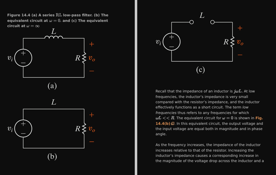


Solve

Describe Low-pass filters:
The series RC circuit:
why it is a low pass filter
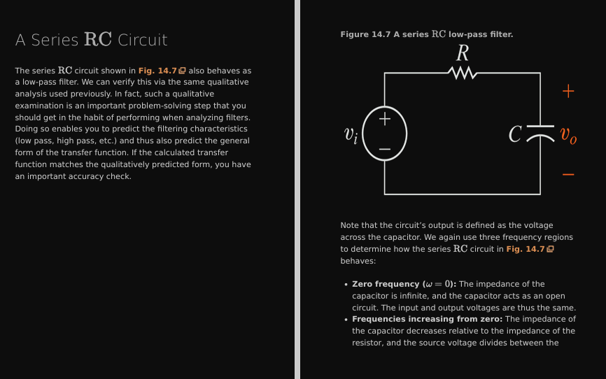


Solve:


Describe lowpass filters:
draw the series RL and RC circuits
derive the transfer function

Describe how to relate the frequency domain to the time domain

Describe high-pass filters:
The series RC circuit
how it forms a high-pass filter
how to analyse it

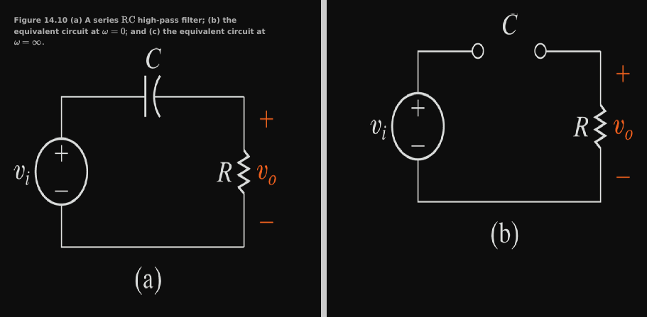

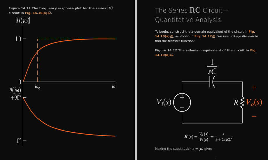


Solve
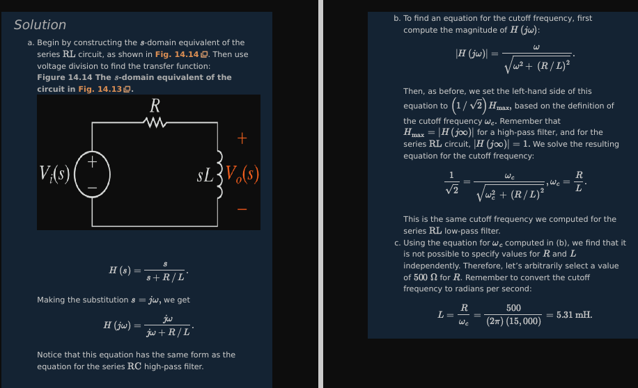
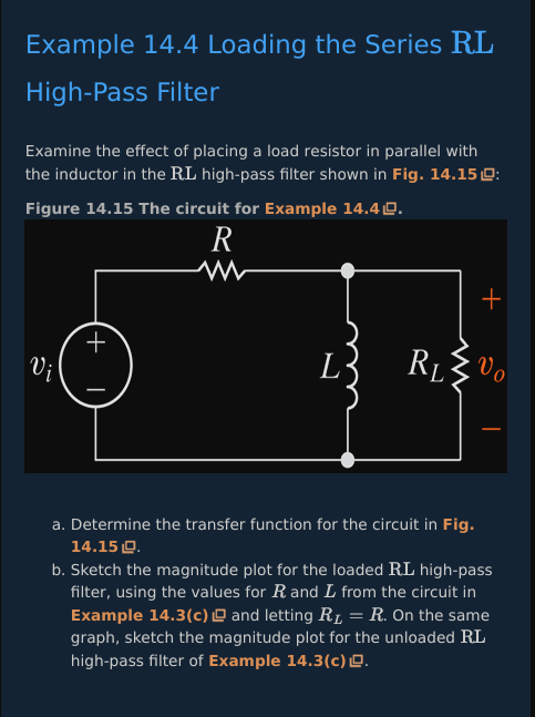
Solve


Describe the transfer functions and cut off frequencies of the RC and RL high pass filter circuits
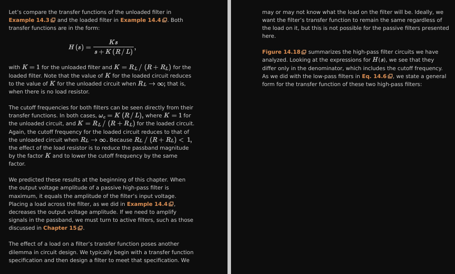

Describe Bandpass filters:
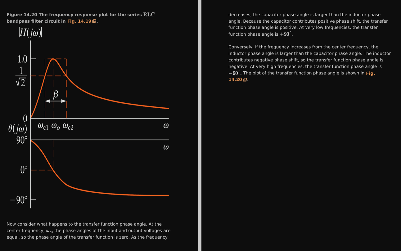
The characteristics of the bandpass filter
the series rlc circuit:
why it forms a bandpass filter
its phase and magnitude plots
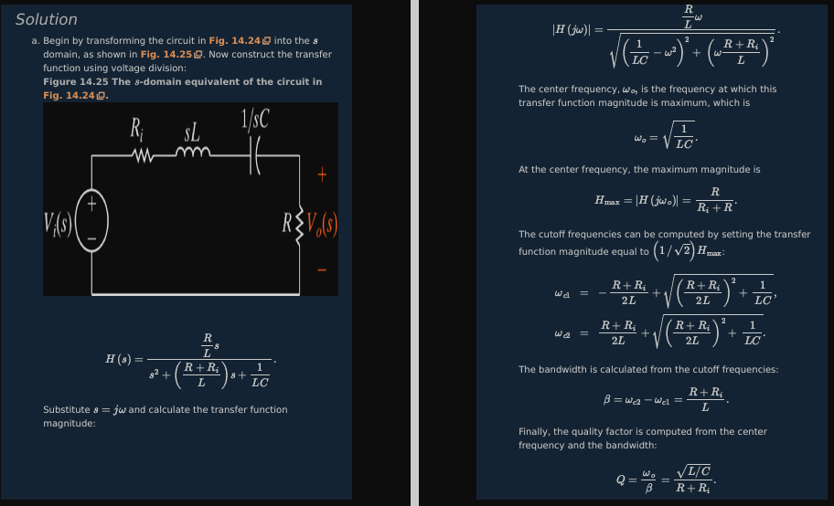
how to analyse it




Solve


Solve


Solve

Describe bandpass filters:
draw the rlc bandpass filter circuits
summarize the transfer functions of the two rlc badnpass filters


For bandpasss filters:
Describe how to relate the frequency domain to the time domain

Describe band reject filters:
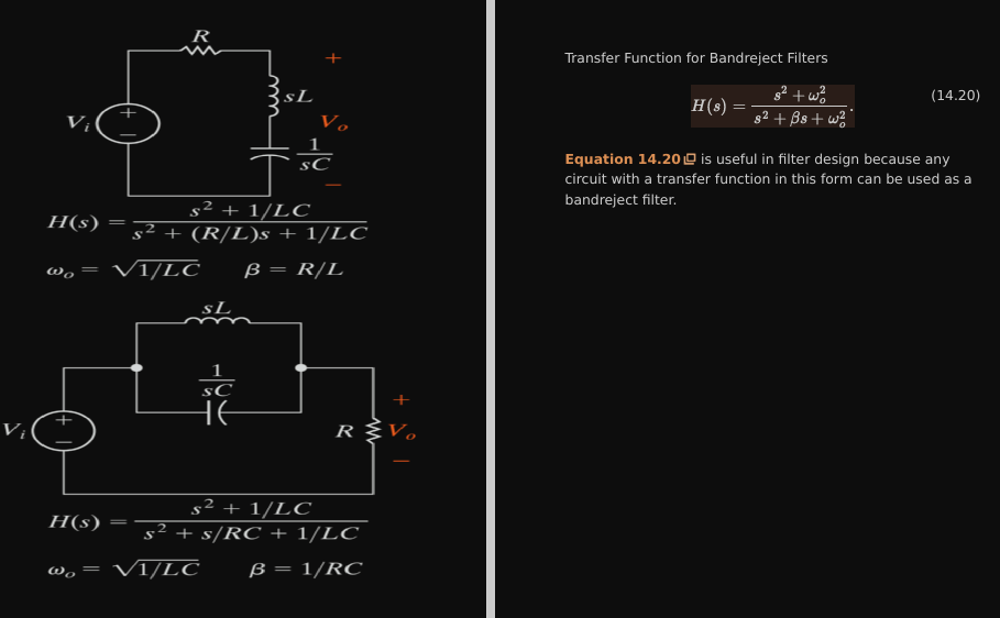
The circuits
why the make up a bandreject filter
phase and magnitude plots
how to analyse the circuits


Solve

Summarize the bandreject circuits and transfer functions