Imaging CT, MRI, Portal, and Ultrasound
 Call Kai
 Learn
 Practice Test
 Spaced Repetition
 Match
 Flashcards
 Knowt Play
1/96

There's no tags or description
Looks like no tags are added yet.
97 Terms
What are the layers of an EPID panel?
Cover
air gap
Copper plate
Scintillator (CsI)
Photodiode array
TFT array
What is a direct conversion flat panel?
Photoconductor converts x-ray energy into electrical charge that is recorded in the TFT array
What is an indirect conversion flat panel?
X-rays are converted into visible light
That light is then converted into an electrical signal
Needs a scintillator
How does an EPID panel work?
x-rays interact with a copper layer where Compton scattering interaction take place
Electrons from the copper interact with a scintillator to produce visible light
The light reaches an array of photodiodes which convert light into electrical charge
Charge is stored for each pixel and is proportional to the detected signal
Thin film transistors (TFT) sequentially read out the charge from each pixel
The electrical signals are digitized and reconstructed into a 2D image
What are EPID panels used for?
position verification
Treatment field verification
dosimetric measurements
What is the difference between MV and kV EPID panels
MV panels: lower contrast from Compton scattering, need copper plate to improve response
kV panels: great photoelectric contribution, higher contrast
Advantages and limitations of indirect EPID
widely used technology
good sensitivity
light spread can reduce resolution
scintillator afterglow can casue lag
Advantages and limitations of direct EPIDs
avoids scintillator light spread
potentially better spatial resolution
charge trapping can affect signal
requires high voltage across photoconductor
What corrections are needed for EPIDs?
Flood field maps: correct for detector response non-uniformity
What are flex maps?
used to correct for changes in EPID response casued by mechanical flexing of the detector as its position or orientation changes
Gravity can cause mechanical deformation of the panel and support arm leading to changes in the detector’s geometry/pixel position relative to the beam

Dead pixel map
represents the locations of pixels that don’t respond correctly
Acquired using a flood image
Values can be replaced with the average value of surrounding pixels

dark image correction
Some pixel values have background values greater than zero (noise)
Dark image is acquired without radiation and is subtracted out

Gain image correction (detector sensitivity)
Accounts for differences in detector sensitivity
Gain image is acquired by averaging a series of homogenous fields and is also corrected using the dark image
How does CBCT work?
Planar projection images are acquired as the x-ray source and panel move around the patient
3D volumetric images are reconstructed from the projections using filtered backprojection
Why is CT image quality better than CBCT?
Geometry
Fan beam used in CT has less scatter radiation that reaches the detectors
Longitudinal divergence of the beam in CBCT causes geometric artifacts
What is T1 relaxation?
Spin-lattice interaction
Result of dissipation of absorbed energy into the molecular lattice
What is T2 relaxation?
Spin-spin interactions
Comes from loss of phase coherence of individual spins caused by magnetic inhomogeneities of surrounding spins
What are the TR and TE for a T1 weighted image?
Short TR (500 ms): maximizes differences in longitudinal magnetization
Short TE (8 ms): suppresses T2
What are the TR and TE for a T2 weighted image?
Long TR (3000 ms): reduces T1 effects
Long TE (100 ms): maximizes T2 differences
What are the TR and TE for a proton density images?
Long TR (2400 ms)
Short TE (30 ms)
Parameters for a head CT
120 kVp
350 mAs
0.5 pitch
50 mGy
Parameters for an abdomen CT
120 kVp
150 mAs
0.5 pitch
15 mGy
What is the impact of increasing peak potential (kVP0?
decreased patient dose
decreased soft tissue contrast
What is the impact of increasing beam current (mA)
increased patient dose
reduced image noise
What is the impact of increasing pitch?
decreased scan time
decreased patient dose
decreased image resolution
increased image noise
What contrast agents are used in CT?
Iodine - vascular studies
Barium - gastrointestinal studies
What are the CT parameters for a 4DCT
120 kVP
800 mAs
0.1 pitch
80 mGy
High vs low compressibility in ultrasound
High compressibility = slow speed
greater stiffness = high speed
What is the speed of sound for air, tissue, and water?
Air = 330 m/s
tissue = 1540 m/s
water = 1480 m/s
What is the range of medical ultrasound
1-20 MHz
50+ for specialized applications
What impacts the speed of sound in different tissues
acoustic impedance - product of density and speed of sound
basis for echo formation
reflection and refraction occur at tissue boundaries that have different acoustic impedance
What is the impact of higher frequencies in ultrasound
provides better resolution
higher attenuation
limited depth of penetration
How are ultrasound pulses created
Pulses are created using a short duration voltage spike in the compression mode
The piezoelectric vibrates at a natural frequency in the thickness mode of l/2
Crystal thickness determines frequency
Why is gel used with ultrasound?
used to improve contact and eliminate air pockets that impact the speed of sound
What are the types of resolution in ultrasound
Axial: ability to distinguish closely spaced objects in the direction of the beam (1/2 spatial pulse length)
Lateral: perpendicular to the beam (beamwidth is determining factor)
Elevational: slice thickness resolution (depth dependent)
How does ultrasound work
ultrasound waves are transmitted into the patient
Partial reflections from tissue boundaries create echoes that return to the transducer as a function of travel time and depth (acoustic impedance)
Receiver detects echoes to form images
TG-66
CT simulator QA
TG-233
CT sim performance
TG-291
Multi energy CT
TG-126
PET/CT acceptance and QA
TG-284
MRI sim
TG-128 and TG-154
Ultrasound
TG-58 and TG-307
EPIDs
TG-104
In room kV imaging
TG-75 and TG-180
image guidance doses
TG-76
Respiratory motion management
How do you measure coincidence of PET and CT components
phantom that has wires with radioactive solution
Image using both
Tolerance is 1 PET voxel
What are the HU and ED values for lung, soft tissue, bone, and titanium?
Lung: 300 HU and 0.3 g/cc
Soft tissue: 100 HU and 1.05 g/cc
Bone: 500 HU and 1.3 g/cc
Titanium: HU saturates and 4.3 g/cc
How do we test for B0 homogeneity
two images with different TE and post process them
What artifacts would a hip implant cause
photon starvation (not enough signal reaches the detector)
Beam hardening - streaking
How do you get rid of artifacts from a hip implant
take an MV image because more photons would get through
IR DECT can get rid of beam hardening but not starvation
What are the components of a CT
X-ray tube – produces the x-ray beam
Filtration and collimation – shape and filter the beam
Detector array – measures
Gantry – the home for the x-ray tube and detectors
Bow Tie filter – attenuates the lateral portion of the beam
CT elevator pitch
The x-ray tube rotates around the patient to acquire projections from different angles
As the x-ray passes through the patient it will be attenuated by different tissue types
After the x-ray has passed through the patient the detector element measures the remaining intensity
The projection data is collected and processed to reconstruct cross sectional images
What is filtered backprojection?
Takes the projections from the different gantry angles and evenly projects them backward across the slice
With many different angles used an image will start to form
Back projection alone will cause there to be 1/r blurring
A ramp filter can be used to eliminate the blurring by suppressing low spatial frequencies, but increases noise from the unsuppressed high frequency portion of k-space
Roll off is used to reduce the high frequency noise amplification
Convolution with a kernel helps with sharpness and smoothing
What is iterative reconstruction?
starts with an estimated image and repeatedly compares the forward-projected data from that image with the actual measured projection data. The algorithm calculates the difference (error) and updates the image until the difference is minimized.
What is the impact of thinner slices?
Thinner slices will improve longitudinal spatial resolution but cause an increase in noise
What is pitch?
Pitch is the ratio of the distance the CT table travels during one 360° gantry rotation to the total beam collimation width.
Pitch = 1: Table advances one beam width per rotation, with no overlap or gap in nominal coverage.
Pitch greater than 1: Table moves farther per rotation, resulting in less overlap, faster scanning, and generally lower radiation dose. However, image noise and artifacts may increase depending on scanner settings and reconstruction.
Pitch less than 1: Table moves less per rotation, resulting in overlapping data, increased radiation dose, and potentially improved image quality.

Ring artifact
detector element malfunction and calls for recalibrating the pixel map

Beam hardening
Lower-energy photons are preferentially attenuated by dense, higher-Z structures, so the average energy shifts upward with increasing path length.

Streak artifact
attenuation exceeds the dynamic or effective linear range of the detectors

Photon starvation
Too few photons surviving the longest densest path, projections are dominated by noise

Partial volume
occur when the reconstructed voxel dimension is large relative to structures in the patient, so a voxel encompasses several tissue types and their attenuation is averaged, diluting the contrast of the small structure

Aliasing
too few projection views to reconstruct high-frequency objects
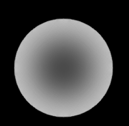
Cupping
mostly caused by scattered radiation, with beam hardening contributing and also causing streaking
Reduce by anti scatter grid between the object and detector
Why are PET/CT scanners combined?
Images are easy to register since the patient is in the same position
CT gives attenuation correction factors to get a more accurate PET image
MRI elevator pitch
Strong magnetic field is applied to a patient
Protons align with the magnetic field and precess
RF energy is applied to convert longitudinal magnetization into the transverse plane
After the pulse, lateral magnetization decays and protons dephase back to longitudinal plane
Receiving coils detect emitted RF waves and record signal
Signal comes from the changes in bulk magnetization
How are MRI images reconstructed?
All voxels in a row are read out simultaneously
Data has to be deconvolved by an inverse Fourier transform in k-space
K-space is a frequency map
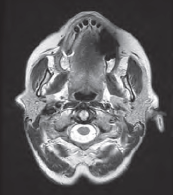
Susceptibility
Usually appears as darkening
Comes from changes in the magnetic field from ferromagnetic, paramagnetic, or diamagnetic materials

Wrap around
Most common in the phase encode direction
Caused by sampling below the Nyquist frequency (lowers apparent frequency)
Increase field of view, change phase encode direction, or oversampling

Distortion
Non-uniformity of the magnetic field that leads to inaccurate encoding of the spatial position
Check for proper shimming, use lower field strength scanner, place ROIs in the field center (area of lowest distortion)
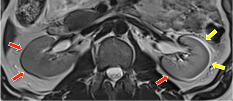
Chemical shift
Appears as dark or light edges on borders with different chemical compositions
Differences in intrinsic shielding of structures\
Use a higher bandwidth or use a lower field strength scanner
Fat and water signals
What are the differences between types 1 and 2 chemical shifts?
Type 1 causes spatial displacement of fat relative to water, while Type 2 causes signal cancellation at fat–water boundaries.
Ultrasound Elevator pitch
Uses high frequency sound waves to produce images
We are measuring the waveform (need time and amplitude)
Transducer emits an ultrasound beam that travels through the patient’s body
Different tissue have different acoustic impedances which impact how much of the ultrasound power is reflected to the transducer to be detected
The computer uses the time between emission and reflection to determine the object distance
Produces an image based on the distance to reflection and the intensity of the reflection
Describe an ultrasound transducer
Used to produce and detect the ultrasound waves
Takes electrical signals and converts them into mechanical signals
Use piezoelectric crystals to create sound pressure waves
Crystal mechanically deforms when electrical signal is applied creating the ultrasound wave
What are the QA tests for ultrasound


Shadowing
Region of hypo intense signal often distal to high attenuation objects

Enhancement
Hyper intense signal that is distal to low attenuation objects

Reverberation
Hyper intense repeating signal
Repeated reflections between two closely spaced objects

Speed Artifact
Abrupt mis-mapping of an object along the beam axis
Caused by variations of the speed of sound between beam projections
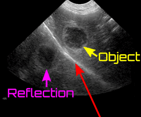
Mirroring
Second inverted object appears beyond a highly reflective surface
Caused by multiple beam reflections between the object and a highly reflective surface
Describe MV imaging
Uses the linac’s photon beam and imaging panel to get portal images
Primarily used for patient positioning and alignment using bony anatomy
Doesn’t have good soft tissue contrast because there is greater Compton scatter and less photoelectric effect
Describe kV imaging
kV imaging
Uses an x-ray source and detector panel that are mounted onto the linac
Gives better image contrast and spatial resolution than MV imaging
Generally, delivers less imaging dose than MV
What corrections are needed for EPID images
Dark-field correction: Removes background signal and electronic noise present when no radiation is delivered.
Flood-field (gain) correction: Corrects for variations in pixel sensitivity and detector response to produce a uniform image.
Bad-pixel correction: Identifies and interpolates defective or nonresponsive detector pixels.
Geometric correction: Corrects image distortion, scaling, and alignment errors.
Backscatter correction: Accounts for radiation scattered from the EPID support arm and detector housing.
Lag/ghosting correction: Accounts for residual signal from previous irradiations that can affect subsequent images.
What are the MRI safety zones
Zone 1 uncontrolled
Zone 2 uncontrolled, where screening occurs
Zone 3 controlled, control room, level 1 escort
Zone 4 MRI, level 2 escort.
MRI QA Tolerances
Percent integral Uniformity >82%f or 3T or 87.5% for 1.5T and below)
Percent signal ghosting < 2.5%
LCV: >38 of 40 spokes for 3T. System dependent
Distortion < 1 mmSRS, 2 mm other
Geometric accuracy 190 ± 2mm
Resolution 1 mmshould be visible (10 lp/cm)
Slice thickness 5 ± 0.7 mm (this is testing RF BW)
Slice position: this is testing slice selection gradient
B0 homogeneity RMS < 0.5 ppm. (1.5 μT variation for 3T*0.5/1E6)
B0 field drift <0.25 ppm/day(after commissioning)
Transmitter gain <5%(analogous to 5 HU tolerance for water on CT)
Transmitter gain = power required (on 𝐵HRF pulse) to flip by desired flip angle
What is the attenuation for ultrasound
0.5 dB/cm/MHz
What are the impacts of increasing kV
raises the max energy of the bremsstrahlung spectrum
shifts the spectrum to higher energies
exposure is proportional to kV²
How is CTDI measured
100 mm pencil ionization chamber in a 16 or 32 cm PMMA phantom
normalized by nominal beam width
volume correction 1/3 center 2/3 peripheral
Amplitude sorting
bins by geometric displacement level of respiratory trace
Can miss data if amplitudes vary
Phase sorting
divides each cycle into equal time fractions
assumes each respiratory cycle has the same duration and shape
What are the EPID requirements for dosimetry
positioning: 2mm
Linearity: 2%
Uniformity: 2%
Reproducibility: 2%
What impacts MRI slice thickness
z = BW/(gyromagnetic ratio * slice select gradient strength)
Typical imaging doses
CT: 10-30 mGy
4DCT: 20-60 mGy
MV: 2 cGy
kV; 1 mGy
kV CBCT: 10s mGy
MV CBCT: 10s cGy
Explain the different gradients used in MRI
MRI uses three magnetic field gradients to localize the signal. First, a slice-selection gradient is applied during RF excitation, causing protons at different positions to have different Larmor frequencies. An RF pulse excites only protons within the desired frequency range, selecting a slice. Next, a phase-encoding gradient is briefly applied, producing position-dependent phase shifts along one direction. Finally, a frequency-encoding gradient is applied during signal acquisition, producing position-dependent frequencies along the other direction. The acquired signals are stored in k-space and reconstructed into an image using a Fourier transform.
How is k-space filled?
K-space is filled line by line using phase and frequency encoding. After slice selection, a phase-encoding gradient is applied to establish a particular phase shift. A frequency-encoding gradient is then applied during signal acquisition, collecting data across one line of k-space. The sequence repeats with different phase-encoding gradient strengths until all required lines are collected. The center of k-space contains low spatial frequencies that primarily determine image contrast, while the periphery contains high spatial frequencies that determine fine detail. Once filled, a 2D Fourier transform converts k-space data into the final image.
What contrast agents are used for MRI
Gadolinium
Iron oxide
Why is the CT to ED curve different for different energies
TC-to-electron density curves differ at 80 and 120 kVp because the X-ray energy spectrum changes with tube voltage, and different tissues have energy-dependent attenuation properties.
Lower kVp produces lower-energy photons, increasing the relative contribution of photoelectric absorption, particularly in high-atomic-number materials such as bone.