Tubes, Extension, and Torsion
 Call Kai
 Learn
 Practice Test
 Spaced Repetition
 Match
 Flashcards
 Knowt Play
1/53

There's no tags or description
Looks like no tags are added yet.
54 Terms
arterial mechanics
Changes of mechanical properties as a result of disease could possibly be used as a marker for the disease
e.g., “hardening of the arteries in atherosclerosis
Changes of mechanical properties may lead to additional/augmented disease states
e.g., decreased bloodflow can lead to ischemia
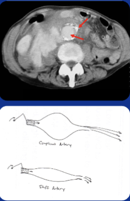
Vein Graft Intimal Hyperplasia (IH)
Autologous saphenous vein remains the graft material most often used in bypass procedures.
Lumenal narrowing by IH is a primary mode of failure for autologous vein grafts, both in coronary and lower extremity positions.

physical problem with vein graft
The vein segment, normally subjected to relatively lower
and static pressure conditions, is placed in the higher-
pressure arterial system.
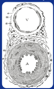
Urinary System
filters blood to remove waste products and extra water, turning them into urine

female urethra
3 to 4 cm long. Smooth muscle, involuntary control. Striated (skeletal) muscle, voluntary control. Urinary incontinence a significant problem in women’s health

compliance
how much deformation per unit force. Apply pressure → tube expands. treated as linear for each pair.
the measure of how easily a biological tissue, organ, or mechanical system deforms or stretches under an applied force or pressure. It is the mathematical inverse of stiffness (or elastance)
As pressure increases, compliance should decrease because of collagen

collagen
stretch and recruit more wavy fibers than once all are recruited, straighten and increase stiffness.
tubular biomechanics
Po (ext. pressure) = 0
Pi (int. pressure) > 0
Incompressible
Axisymmetric
Linearly elastic material
No axial variations in stress
No shear stress

axisymmetric
same stress no matter where we go around tube → things constant with length (no axial variations)
an object, system, or physical field has symmetry around a central axis, meaning its properties do not change when rotated around that axis by any angle.
incompressibility
constant volume.
a physical property where a material's volume and density remain constant even when subjected to external pressure changes or forces
If length is constant, area is also constant

criteria for thick wall
t/R < 0.05 → Thin wall → Law of Laplace
t/R > 0.05 → Thick wall → Lamé Solutions

Classic Lamé Solutions
In solid mechanics, Lamé's solutions apply to axisymmetric boundary value problems (such as thick-walled cylinders or spheres under internal and external pressure, derived using Lamé's stress potentials and the Lamé elastic constants λ and μ)

solution to Lame equations

tangential stress distribution
in a thick-walled cylinder varies non-uniformly across the wall thickness according to Lamé's equations
Unlike thin-walled vessels where hoop stress is assumed uniform, tangential stress in thick-walled cylinders changes significantly as the radius r goes from the inner wall to the outer wall.

radial stress distribution
across a thick-walled cylinder is non-uniform and is determined using the Lamé Equations
• Inner Surface: If there is only internal pressure and zero gauge external pressure, the radial stress equals the negative of the internal pressure, acting as a compressive stress.
• Outer Surface: If external gauge pressure is zero, the radial stress drops to 0.
• Variation Across Wall: Unlike thin-walled cylinders where radial stress is assumed negligible, thick-walled cylinders experience a continuous, non-uniform variation of radial (compressive) and hoop/tangential stresses from the inner wall to the outer wall.

Lame vs Laplace
Lamé's equations apply to thick-walled solid tubes under pressure, while Laplace's law applies to thin-walled membranes, biological vessels, and capillary fluid interfaces. Both equations calculate how internal pressure relates to stress or tension in a cylindrical shape, but they solve fundamentally different physics and engineering problems.

aneurysm
using thick walled equations is good for predicting ________ rupture.
a localized, weakened bulge or "ballooning" in the wall of an artery (blood vessel that carries oxygen-rich blood from the heart to the rest of the body).

bubble inflation testing

incremental elastic modulus
Here, Δb is the change in outer radius that arises from a change in internal pressure of ΔP
the instantaneous slope of the stress-strain curve at a specific point of deformation
Unlike a standard or secant modulus (which measures overall stiffness from the origin or between distant points), this measures how stiffness changes with small additions of stress and strain during nonlinear, hyperelastic, or plastic deformation.

Stress-Strain Curves
nonlinear increase - different for each region. Proximal stretches most but achieves highest stresses.
a graphical representation in materials science and engineering that plots how much a material deforms (strain, on the x-axis) in response to an applied force intensity (stress, on the y-axis)

urethral isolation

mechanical testing

biomechanical testing
Preconditioning to remove viscoelastic effects
Testing consists of increasing intralumenal pressures from 0-20 mmHg in 2 mmHg steps
preconditioning
the process of treating, conditioning, or adjusting a raw substrate (such as polymers, concrete, food/feed blends, or thermal payloads) prior to a primary manufacturing, testing, or chemical procedure to ensure uniform processing and optimal performance
here, to remove viscoelastic effects
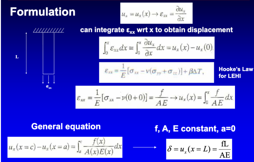
deformation due to extension
occurs when a stretching or tensional force is applied to an object, increasing its length.
• Hooke's Law (F = kΔ L): Within the elastic limit, the extension (Δ L) of a material is directly proportional to the applied stretching force (F), governed by the material's spring constant or stiffness (k). For LEHI materials. Axial stress is constant, applied uniformly over area.
discontinuities
determine internal forces for integrals for each section between these.
a break, jump, or non-uniformity in how a material or structure changes shape, where displacement, velocity, or the deformation gradient is not smooth or continuous across a boundary or interface
→ an applied force or moment; change in area; change in elastic modulus; etc
general solution process for deformation problems
determine all external forces applied to structure. determine all internal/reactionary forces by drawing FBDs
examples of discontinuities
change in area
change in material/elastic modulus
change in force
when there is one, change integrals - separate integrals at point of discontinuity

making cut
do it in the middle of a section, not directly at the discontinuity
Diaphysis
the main or central tubular shaft of a long bone (such as the femur, tibia, or humerus)
Made primarily of dense, hard cortical (compact) bone that provides high structural strength and weight-bearing support
Epiphysis
The rounded end or tip of a long bone that ossifies from a secondary center of ossification.
Composed mostly of spongy (cancellous) bone surrounded by a thin layer of compact bone, and covered at the joint surface with articular cartilage.
Metaphysis
the wide, neck-like portion of a long bone located between the central shaft (diaphysis) and the end region (epiphysis).
During childhood and adolescence, contains the epiphyseal plate (growth plate), a layer of hyaline cartilage that allows the bone to lengthen.
cortical (compact) bone
The dense, hard outer layer that forms roughly 80% of the total skeletal mass in the human body
Provides rigidity, stiffness, and high resistance to bending and torsion, allowing the skeleton to support body weight and muscle movement.
cancellous (trabecular) bone
a porous, honeycomb-like type of osseous tissue that makes up about 20% of the human skeleton
It provides structural integrity, absorbs and dampens sudden mechanical shocks (such as walking, running, or jumping), and reduces overall skeletal weight.
Wolff’s Law of bone remodeling:
collagen fibers align in direction of loading (and subsequent displacement of cells)
artificial hips
clinical relevance - 120,000 implanted annually in the US.
Femoral head subjected to compression, torsion, and bending. Impacts bone remodeling – need to consider loads in implants, transfer of load

assumptions for bone modeling problems
Model problem: axial loading of circular cylinder consisting of two LEHI materials, find forces in both
Bone typically non-homogeneous and anisotropic
Geometry: diaphysis region not perfect cylinder
Unidirectional loading
statically indeterminate
when the number of unknown reaction forces or internal stresses exceeds the available equations of static equilibrium (sum F = 0) and (sum M = 0).

forces in prosthesis design
Don’t want prothesis to break → want to be really strong. Metal really stiff compared to bone. Metal carries all the load. Bad because the bone will atrophy due to disuse. Metal prosthesis designed for only slightly higher stiffness than bone.

torsion analysis
Different for circular, rectangular, etc.
Circular cross-section – twisting does not “warp” the cross-section. Not true for rectangular, elliptical, etc .Focus on circular cross-section, LEHI
torsion
the twisting of a structural member or shaft caused by an applied moment or torque (T) acting about its longitudinal axis
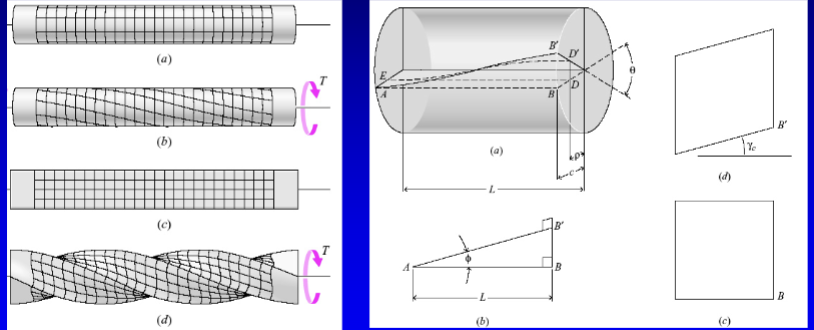
formulation of shear stress due to torsion
Solid circular cylinder
Fixed on one end, free on other
Free end subjected to twisting moment T = Mz
Equilibrium: Equal and opposite reaction torque, Internal torques

Shear stress due to Torsion
σzθ = stress on z face in θ direction
Acts on cut face to balance applied torque T
Acts over respective area
the internal shearing stress created in a structural member, such as a cylindrical shaft, when an external twisting force (torque) is applied
function of radius

shear stress is not constant
σzθ not constant: need to know σzθ as a function of radius in order to solve
Recall that for axially loaded rods, we avoided this by assuming σxx constant over the cross section
gamma variable
γ = Angle of circumferential motion of all material particles along a line on the cylinder
γ = γc for a line along outer radius of cylinder (r=c)

torsion equation
Only holds for small-strain LEHI behavior
Shear stress varies linearly with radial position
Failure – of LEHI material, most likely at outer circumference

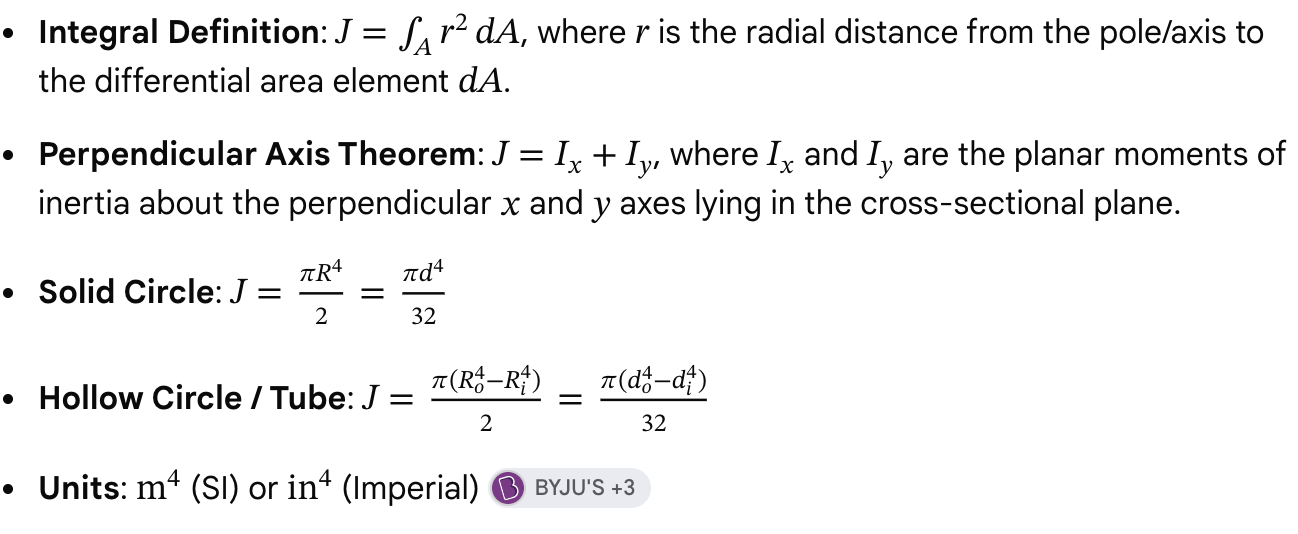
polar moment of inertia (J)
measures an object's resistance to twisting (torsional deformation) around a longitudinal axis
heart
biological application of torsion.
Heart muscle twists upon ejection of blood. Unique arrangement of cardiac muscle fibers

implants
biological application of torsion.
Hip: Femur and Acetabulum
Transferred load not along implant shaft. Bending and twisting moments

different coordinate system
Recall: relate components of stress in a Coordinate
System to those in another CS
• Rewrite in Cylindrical / Polar Coordinates x → z, y →θ
General Pure Torsion: σzz, σθθ = 0

Principal Stresses and Strains in Torsion
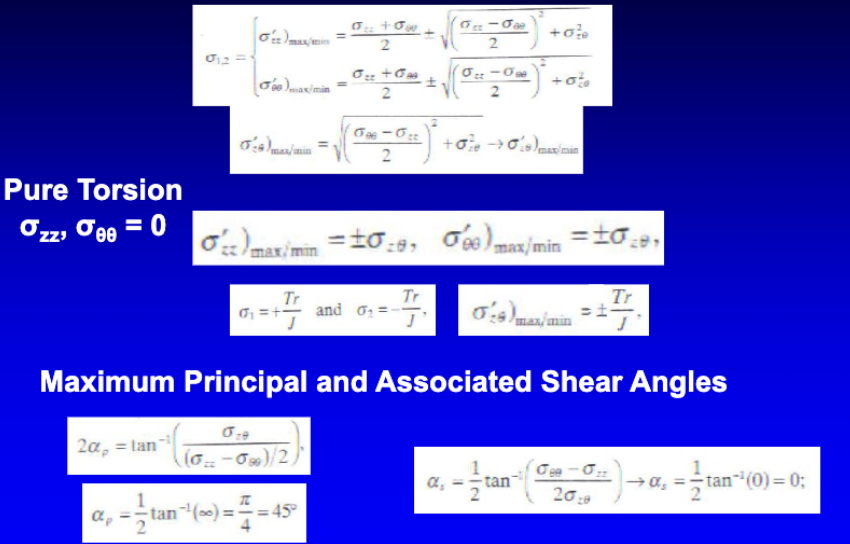
principle stresses in torsion
Under pure torsion of a circular shaft, a small surface element experiences only shear stress Txy = Tr/J, where T is torque, r is radius, and J is the polar moment of inertia) with zero normal stress on the longitudinal and transverse planes.
Principal Stresses (σ₁, σ₂)
Using Mohr’s circle for pure torsion, the center of the circle is at the origin (0,0) and the radius equals the maximum shear stress \(\tau_{max} = \frac{Tr}{J}\).
• Major (tensile) principal stress (σ₁): σ1 = +τmax= +Tr/J
• Minor (compressive) principal stress (σ₂): σ2 = -τmax= -Tr/J
• Orientation: These principal stresses act on planes oriented at 45° (rotated by 90° on Mohr’s circle) to the longitudinal axis of the shaft. On these 45° planes, the normal stresses reach their maximum absolute values, and the shear stress is zero.
principle strains in torsion
Relating stress to strain via Hooke's law for plane stress (with shear modulus G and Poisson's ratio ν):
• Principal strains: ε1, ε2 = τmax/2G}(1 + ν)\ = ± γmax/2
• Strain gauges placed at 45° to the longitudinal axis align with these principal directions to directly measure principal tensile and compressive strains.
Maximum Angle of Twist in Torsion
For a circular shaft under torsion is calculated using the formula Angle of Twist Interactive Calculator
Φ = TL/JG
• T: Applied internal torque (N m(
• L: Length of the shaft segment (m)
• J: Polar moment of inertia (m4)
• G: Modulus of rigidity (shear modulus) of the material (Pa)
