RTR.6 Analyzing IQ and Responding
 Call Kai
 Learn
 Practice Test
 Spaced Repetition
 Match
 Flashcards
 Knowt Play
1/44

There's no tags or description
Looks like no tags are added yet.
45 Terms
Spatial Resolution
ability to image small objects that have high subject contrast
affected by focal spot size (smaller the better) and detector material
Contrast Resolution
ability to differentiate/image structures with similar density
improves with low kVp
Subject Factors that Affect IQ
subject contrast
patient thickness → thicker = more absorption
tissue mass density → denser = more absorption
atomic number → higher = more scatter
object shape
Window Width
the number of Hounsfield units represented on a specific image
Wide WW
Best for imaging tissues with high contrast
Reduces image contrast, but also suppresses noise, thus often used for obese pts or for metallic objects
Narrow WW
best for low contrast tissues eg. brain
Window Level
The centre value of the WW thus selects which Hounsfield values are displayed as shades of gray
Should be set at a point that is roughly the same value as the average attenuation number of the tissue of interest
Factors that Increase Scatter Radiation
high kVp and also high mA
large field size
increased patient thickness
Lossless Image Compression
can be reconstructed to be the same as the original image, 10:1 or 2:1
Lossy Image Compression
can provide compression factors of up to 100:1 or greater; not acceptable for archiving any images as it represents a lack of data
XR Preprocessing Components
interpolation = for dead pixels
flatfielding = equalizes the response of each pixel to a uniform X-ray beam, eg., anode heel effect
CT Artifact - Aliasing
Insufficient projection data (aka undersampling), due to extended helical pitch
Consist of evenly spaced lines, easy to distinguish from anatomic structures, thus rarely render an image undiagnostic
CT Artifact - Beam Hardening
Can produce either cupping artifacts (the periphery of the image is lighter) or streak artifacts (of dark bands or streaks between dense objects)
Filtration, bow tie filter, increase kVp, select appropriate SFOV

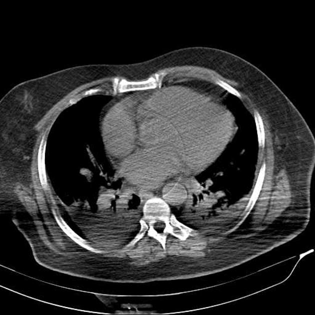
Beam Hardening Artifact
CT Artifact - Partial Volume
When a dense object is lying at the edge of FOV, it may only show up in a small number of views
Use thinner slices

CT Artifact - Edge Gradient
Due to irregularly shaped objects that have a pronounced difference in density from surrounding structures
Unavoidable, but can be reduced by thinner slices

CT Artifact - Ring
Caused by imperfect detector elements—either faulty or simply out of calibration
Appear as a ring or concentric rings centred on the rotational axis


What type of Artifact is this?
Motion Artifact
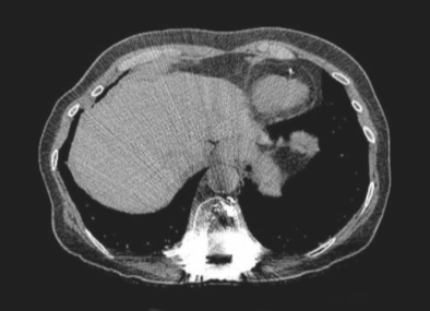
What type of Artifact is this?
Metallic Artifact

What type of Artifact is this?
Out of Field Artifact
Caused by anatomy beyond the SFOV hardening the beam, but ignored in the reconstruction process eg. arms being by the side
QC - Exposure Reproducibility
ensuring that an X-ray generator always produces the same intensity each time with the same set of technical factors; maximum variability is +-5%
QC - Beam Quantity
X-ray generators should emit a specific amount of radiation per unit of X-ray tube current and time; maximum variability is +-10%
QC - Kilovolt Accuracy
the kV stated on the control panel should produce an X-ray beam with a comparable and consistent amount of energy; maximum variability is +-5%
QC - Timer Accuracy
to ensure accurate exposure timer; +-20% for exposure times less than 10 ms
QC - mA and Exposure time Linearity and Reciprocity
to ensure constant radiation output with various mA and exposure time combinations
eg. g. 50 mA at 1sec and 100 mA at 0.5sec, both with the same kVp, should yield the same amount of radiation output
+-10%
QC - Linearity
sequential increase in mAs should produce the same sequential increase in the exposure measured, +-10%
QC - Repeat Analysis
monthly
Casual repeat rate = repeat for specific cause / total repeats
Total repeat rate = total repeat images / total exposures
Repeat rates should be less than or equal to 5%
Rates between 10-12% should be seriously examined
QC for DSA
needs a weekly QC to evaluate DSA function with a DSA phantom
QC for Fluoro
Quarterly QC to evaluate table angluation accuracy and smooth motion
QC - Electronic Display Device Performance
Yearly, SMPTE and/or TG-18 to assess for any
Distortion
Reflection
Luminance
Resolution
Noise
Glare
Chromacity (quality of colour)

Bolus (arterial) Phase
Immediately follows injection
HU difference of 30 or more between the aorta and IVC
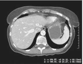
Non-equilibrium (venous) Phase
1min post injection
HU difference between 10-30

Equilibrium (delayed) Phase
2min post injection
HU difference less than 10
Wide Histogram =
peaks on the far ends of the graph = lots of white and black shades
high contrast image

Narrow Historgram
peak is at the center of the graph = similar shades of gray, low contrast
Lateral Hip BTP
good 45 angle to FN → GT and LT SI prox/dist
beam to // → LT proximal to GT
beam to perp → LT distal to GT
Lateral Hip Rotation
no pelvic rotation → ischial tub squared
good int.rot leg → GT SI over fem neck and LT seen post
ext.rot of leg → GT is post and LT is SI by femoral shaft
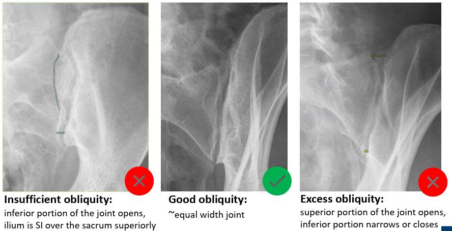
AP OBL SIJ Rotation
good rotation = equal width of joint opened
insufficient = superior joint is closed
excessive = inferior joint is closed
Cranium F/E
perp, OML = petrous at supraorbital
15 caud or rasie OML 15 = petrous at lower 1/3 of orbits
30 caud or raise OML 30 = dorsum sellae and clinoids visualized in the foramen magnum
Externally Rotated Humeral Head
lateral GT
LT is midway between HH and GT

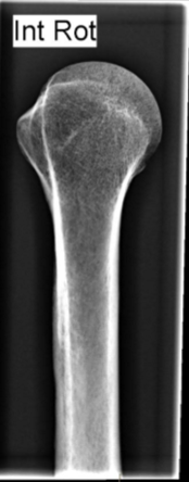
Internally Rotated Humeral Head
medial LT
Neutral Rotation Humeral Head
both GT and LT seen end on

LPO and RAO C-Spine OBL demonstrates
right pedicles in profile and left pedicles aligned to the anterior VB

RPO and LAO C-Spine OBL demonstrates
left pedicles in profile and right pedicles aligned to the anterior VB
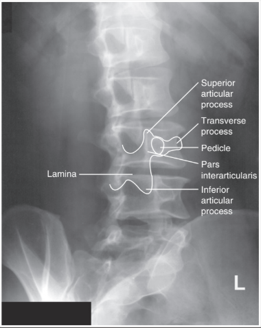
Lumbar Spine OBL - Rotation
good = 5 stacked scottie dogs
insufficient = closed Z-joint, pedicle (eye) is closer to the lateral VB
excessive = closd Z-joint, pedicle (eye) is more midline of the VB