RESP 210 quiz 2 study guide
 Call Kai
 Learn
Learn Practice Test
 Spaced Repetition
 Match
Match Flashcards
 Knowt Play
1/103

There's no tags or description
Looks like no tags are added yet.
Name | Mastery | Learn | Test | Matching | Spaced | Call with Kai | Chat |
|---|
No analytics yet
Send a link to your students to track their progress
104 Terms
Inspiratory and expiratory accessory muscles consist of
insp
scalenes
sternocleidomastoids
pectoralis major/minor
trapezius
exp
rectus abdominus
transverse abdominal
external oblique
internal oblique
latissimus dorsi
boyle’s law
the pressure of a gas will ↑ as volume ↓ with constant mass and temperature
P1V2= P2V2
PIP definition
Highest pressure reached during inspiration
the total pressure during flow
Represents the total pressure required to
move gas
expand the respiratory system
PIP= baseline + restrictive pressure + elastic pressure
what does PIP overcome?
What does PIP expand?
The pressure needed to overcome:
Airway resistance (Raw)
The pressure needed to expand:
the lungs and chest wall
definition of Pplat
pressure remaining when flow stops
Approximates alveolar pressure
reflects
elastic load
respiratory-system compliance
What does Pplat represent
the pressure needed to
hold the delivered volume in the alveoli.
when is Pplat measured?
Measured during an inspiratory hold
No gas flow = no resistive pressure
what is the equation for driving pressure
Pplat - PEEP
how does PIP and Pplat effect compliance and Raw?
↓ compliance
↑PIP ↑Plat
good compliance
↓PIP ↓Plat
↑ Raw (airway resistance)
↑PIP
bigger PIP to plat difference
smaller PIP to plat difference
↓ Raw (airway resistance)
OR normal

for plat, does Raw contribute to measured pressure?
With no gas flow, airway resistance no longer
contributes to the measured pressure
what equation measures the pressure used to overcome airway resistance (Raw)?
PIP-Pplat
equations for Pta, Ptt, Ptr, Ptp
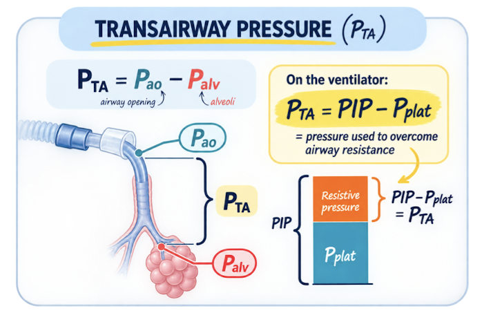
PTA = PIP – Pplat or PTA = Pawo – Palv
Transairway pressure
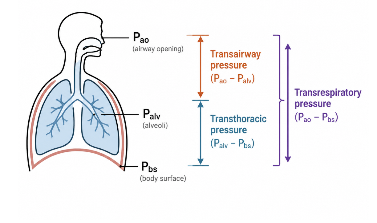
PTT = Palv – Pbs
Transthoracic pressure
PTR=PTA+PTT or PTR= Pawo−Pbs
Transrespiratory pressure
PTP= Palv - Ppl
Transpulmonary pressure

What is the definition for Pta
Pressure difference between
airway opening
the alveolus
The pressure required to
overcome airway resistance
move air through the airways
What is the definition for Ptt
This pressure gradient is the difference between
the alveolar space
the pressure at the body surface.
It’s the pressure required to expand
the lungs AND chest wall together

What is the definition for Ptr
Pressure across the entire respiratory system
During positive-pressure ventilation, ____ is the total pressure required to move air through
the airways
and expand the lungs and chest wall.
What is the definition for Ptp
the difference between
alveolar pressure
pleural pressure
what is PTP also called
alveolar distending pressure
keeps the alveoli open
for Palv, what can also be used?
plateau pressure
equation for Vt (volume), flow, time
VT (volume) = flow x Ti
flow = VT/Ti in L/sec
Ti= VT/flow
what is compliance
COMPLIANCE = Ease of Expansion
C= ΔV / ΔP
Units: mL/cmH₂O
High vs. low compliance
High compliance: more volume produced by less pressure required
Low compliance: stiff respiratory system; more pressure required
what is the definition for static compliance
Reflects the elastic properties of the lungs &chest wall
Lung compliance measured during a period of no airflow
what is the equation for static compliance
Cstat= (Vte) / (Pplat−PEEP)
units of mL/cmH2O
ex:A patient is on AC/VC with Vt = 400 ml, RR = 18, PEEP = 5cmH2O, FiO2 = 50%. Measured values are Vte = 415 ml, PIP = 26 cmH2O and PPlat = 23 cmH2O.
Cstat = Vte / (Plat - PEEP)
Cstat = 415 ml / (23-5 cmH2O)
Cstat = 23.05~ about 23.1 mL/cmH₂O
what is the normal value for static compliance
40-50 to 100 mL/cmH2O male
35-45 to 100 mL/cmH2O female
what is the application for static compliance
Low Values (< 20 mL/cmH₂O): Indicate stiff lungs or decreased elasticity
seen in
ARDS
pulmonary fibrosis
PNA
pulmonary edema
what is the definition for dynamic compliance
alveolar elasticity and the pressure required to overcome airway resistance during flow
Affected by
compliance (elastic recoil)
Raw (airway resistance)
Accurate measurement requires a passive patient;
spontaneous effort can distort the result.
what is the equation for dynamic compliance
Cdyn= (Vte) / (PIP−PEEP)
units of mL/cmH2O
ex:AC/VC with Vt = 500 ml, RR = 18, PEEP = 5cmH2O, FiO2 = 50%. Measured values are Vte = 510 ml, PIP = 28 cmH2O and PPlat = 25 cmH2O.
Cdyn = Vte / (PIP - PEEP)
Cdyn = 510 / 23 cmH2O
Cdyn = 22.2 mL/cmH₂O
what is the normal value for dynamic compliance
50–100 mL/cmH₂O
what is the application for dynamic compliance
𝐶𝑑𝑦𝑛 is always less than or equal to Cstat
extra pressure is required to overcome airway resistance during gas flow
what is the definition for airway resistance (Raw)
Opposition to Flow
Typical inspiratory resistance with an artificial airway
Bedside clue:
PIP rises while Pplat remains unchanged
what is the equation for airway resistance (Raw)
Raw = PTA / Flow
Raw = (PIP – Pplat) / Flow
in units of L/sec
ex: A patient is on AC/VC on square flow pattern with Vt = 500 ml, RR = 18, PEEP = 5cmH2O, FiO2 = 50%, Ti = 1.0 sec Measured values are Vte = 510 ml, PIP = 28 cmH2O and PPlat = 25 cmH2O.
Square flow = 0.500 L ÷ 1.0 s = 0.5 L/s. → flow= vt/Ti
RAW = (PIP - PLAT) / FLOW (L/S)
RAW = 3 cmH2O / 0.5 L/sec
RAW = 6 cmH2O / L/ sec
What will ↑ Raw
Bronchospasm
Airway or mucosal edema
Secretions
ETT
Small
long
bitten
kinked
Higher inspiratory flow
positioning
what is the normal value for airway resistance (Raw)
6 - 15 cmH₂O/L/s; varies with ETT size and flow
finding LPM
multiple by percentage
ex 1:
Patient is in PS/CPAP mode which is flow cycled. The Esens is set at 75%. The patient's expiratory flow max is 100 LPM. At how many LPM will the breath cycle _____ LPM
75% of 1
75 × 1 = 75
ex 2:Patient is in PS /CPAP spontaneous breathing trial. Expiratory sensitivity is set at 25%. During this breath the maximum flow is 60 LPM. At how many LPM will the breath cycle
25% of 60
25 × 0.60 = 15
An Esens setting of 75% gives a longer Ti than 25%. ?
-no → 75 will give shorte Ti than 25%
what is the definiton for time constant
time it takes for lungs to fill/empty
DIFFERENT LUNG UNITS = DIFFERENT TIME CONSTANTS
uneven distribution of ventilation
Individual lung units vary in compliance and resistance
short vs long time constant
Short time constant: fills and empties quickly
ARDS
pulm fibrosis
advanced ILD
Long time constant: fills and empties slowly
COPD
increased resistance & compliance
Two lung units have the same resistance. One has normal compliance; the other is stiff. Which fills faster—and which receives less volume
The stiff unit has the shorter time constant and fills
faster
receives less volume for the same
pressure
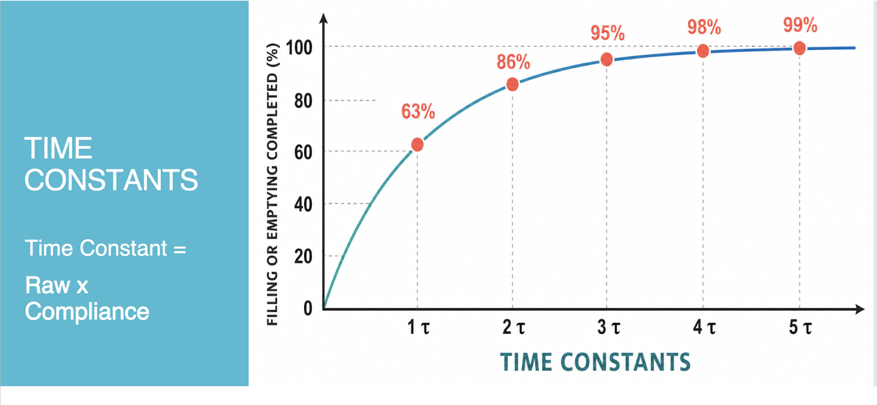
what is the graph for time constant
what is the equation for time constant
TC= Raw x C
ex:
10 × 0.50 ml → 10 × 0.05L = 5s

what is the pecentages for time constant
1 TC
63 %
2 TC
86%
3 TC→ minimum
95%
4 TC
98%
5 TC
99%

Utilizing time constants in an obstructive disease case study

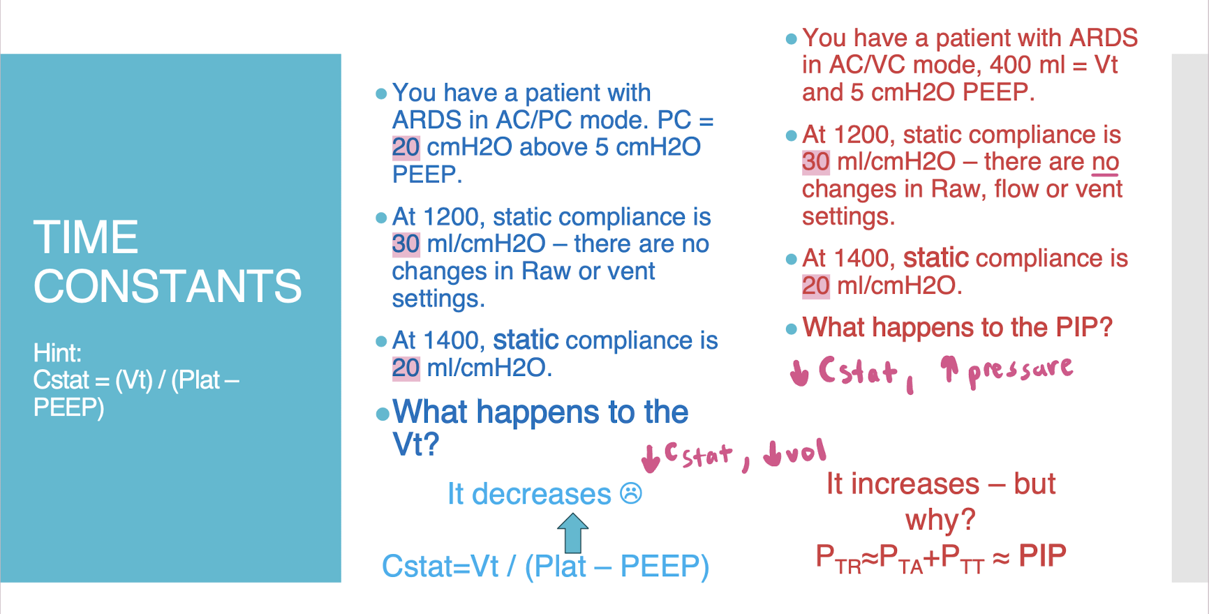
TC for ARDS example
TC example 1:
A COPD patient in an active viral infection has a compliance of 0.055 ml/cmH2O and airway resistance (RAW) = 17.1 cmH2O/L/sec. What is the value of 1 time constant? _____ seconds
17.1 ml/cmH2O/L/sec x 0.055 ml/cmH2O = 0.9405 seconds - normally round to 0.94 but will accept 0.95
TC example 2:
A status asthmaticus with an active viral infection has a compliance of 0.021 ml/cmH2O and airway resistance (RAW) = 84.1 cmH2O/L/sec. What is the value of 1 time constant? _____ seconds.
What is the minimum exhalation time required for 3 constants? i:e? TCT? RR? Ti=0.8s
RAW x C = 84.1 x 0.021 = 1.77 seconds -- should be rounded to 1.8 but will accept 1.7
3 time constants = 3 x 84.1 x 0.021 = 5.2983 seconds - round to 5.3
The i:e is Ti/TI: Te/Ti or 1/1: 5.3/1 = 1:5.3
TCT = Ti + Te or 0.8 seconds + 5.3 seconds or 6.1 seconds
RR = 60 / TCT or 60 / 6.1 = 9.84 breaths/minute or about 10
TC example 3:
You are caring for a patient with severe emphysema. The patient has a compliance of 0.099 L/cmH₂O (99 mL/cmH₂O) and an airway resistance (Raw) of 12 cmH₂O/L/s. What is the minimum amount of time needed for exhalation, assuming 3 time constants?
If you select Ti = 1.2 seconds, what would be the highest possible RR possible to allow the patient enough time to exhale 95% of the air in his lungs
3 TC = 3 x 12 x 0.099 = 1.2 seconds x 3 - round to 3.564 seconds - round to 3.6
TCT = Ti + Te = 3.6 seconds + 1.2 seconds = 4.8 seconds
RR = 60 / TCT --> 60 sec / 4.8 sec = 12.5 breaths - round to 12 or could round to 13
what condition will need longer exhalation time on vent
Status asthmaticus patient
open loop control systems
set → deliver
delivers programmed output
no feedback-based automatic correction
NO feedback
ex:
set VT 500 mL → delivers programmed breath
closed loop control systems
set → deliver → measure → adjust
measures delivered output
compares output w/ set target
uses feedback to adjust subsequent output
FEEDBACK IS GIVEN
ET VT: 450 mL
↓
MEASURED VT: 412 mL
↓
VENTILATOR ADJUSTS OUTPUT
↓
TARGET: 450 mL
positive pressure ventilators
Positive pressure: Increasing pressure at the airway (like CPAP +10 cmH2O or IPAP +20 cmH2O)
▫ +Pressure means pressure at airway> body surface
negative pressure ventilators
negative pressure around the thorax (lowers air pressure around the chest/body surface) → drawing air into the lungs and mimicking spontaneous inspiration
Greater negative pressure→ greater pressure gradient→ greater volume
ex:
Cuirass negative pressure vent
high frequency PPV
Jet (right) uses RR of 400 – 600/minute
fast rate, low Vt
Delivers very small tidal volumes with extremely short Ti
at rates of hundreds of breaths per minute.
Exhalation remains passive. Used primarily for
critically ill neonates
pulmonary interstitial emphysema
RDS complicated by air leaks.
Low peak & MAP may help prevent or allow air leaks to heal
electronically powered ventilator
Electricity provides energy for ventilator operation
AC power from wall outlet
Battery (DC) provides backup/transport power
Powers motors, valves, microprocessors & alarms
pneumatically powered ventilator
Series of tubes that allow gas to flow inside the vent and between the vent and out to the patient (compressed gas source)
Gas flows through pneumatic circuit to get to pt
High-pressure gas provides energy for ventilation
Typically uses
medical air
and/or O2
• Source pressure (50 PSI or other) reduced to operating pressure
Most modern ICU ventilators use pneumatic power for gas
delivery + electrical power for computerized control.
internal pneumatic circuit
external pneumatic circuit
• Do not require electricity for basic operation
• Bird Mark 7 = classic example
• Older technology
Internal vs external pneumatic circuit
Internal pneumatic circuit
Valves & tubing inside the vent that control gas flow
vent to artificial airway
External pneumatic circuit
Also called the patient circuit
Carries flow between vent and patient
Can have external or internal expiratory valve

Parts of a ventilator
Inspiratory limb → carries gas from ventilator to patient
Wye adapter → connects inspiratory + expiratory limbs to patient
Expiratory limb → carries exhaled gas back toward ventilator
Expiratory valve → controls/releases exhaled gas & maintains PEEP
Flow sensor → measures flow near the patient airway

control panel/ user interface
Located on the surface of the vent
Where the operator sets and monitors ventilator function
Controls may include knobs, buttons, or touchscreen controls
Used to set ventilator parameters and alarms

ventilator adjuncts
Humidifier
Temperature probe
Nebulizer
Capnometer
Bacterial filter
In-line suction catheter

components of ventilator
A ventilator has two major components:
1. Drive mechanism – (compressor) which is a mechanical system that produces gas flow to the patient
2. Output control mechanism – one or more valves that determine the flow to the patient
There are two major types of ventilators:
volume displacement
old type
flow control
How vent delivers a breath, how gas moves through all parts of a vent,
Two basic functions:
1. Generate gas flow
A drive mechanism provides the gas/energy needed to deliver the breath
2. Control gas delivery
Valves and the control system regulate flow, pressure, volume, and timing
• Modern ventilators use electronically controlled systems to precisely regulate gas delivery
2 types of valves
flow controlling valve
expiratory valve
3 types of flow controlling valves
proportional solenoid valve
used in ICU
stepper motor valve
not used much
digital valves
on/off configuration
a set of smaller valves
To get more airflow, the device opens more of these small valves

flow-controlled valves
Flow-control valves regulate gas flow to the patient
Valves open and close rapidly in small increments to precisely control gas delivery
Precise regulation of gas flow rate (L/min) into or out of the circuit.
They allow rapid response to changes in flow & Great flexibility in flow control
Allows rapid, flexible control of flow, volume, and pressure
expiratory valves
Control gas leaving the patient circuit during exhalation
May be internal to the ventilator or external in the circuit
Open during exhalation to allow gas to exit the circuit
Help maintain PEEP by controlling expiratory pressure
Expiratory valve = controls exhalation + helps maintain PEEP
4 types of ventilators
High frequency positive pressure vents
infant vents
transport vents
home vents
infanct ventilators
Ventilation for infants is more delicate and often uses different strategies/modes:
Must monitor parameters closely
Provide the appropriate level of support
Respond to physiologic changes quickly
• 2 approaches to infant ventilation
Special ventilators designed exclusively for infants and small children
Single ventilator for all ages “cradle to grave”

transport ventilators
Transport requires the same level of ventilation as bedside care
• Preparation + communication are essential
• Ventilator vs. BVM? Consider the risks and benefits for the individual patient
Transport ventilators should be:
▫ Compact and lightweight
▫ Reliable with adequate battery/gas supply
▫ Able to function in challenging transport conditions
home care ventilators
Home ventilation can provide an alternative to hospital or extended-care settings
Advances in technology allow long-term ventilatory support at home
Home ventilators must be simple, user- friendly, and have clear alarms
Family/caregivers often provide much of the day-to-day care
equation of motion
Pmus + Pvent = Palv + PTA
Control Mode: AC/VC , 70 kg IBW
RR 14 Vt 560 ml FiO2 .60 PEEP 5cmH2O
Patient on heavy dose or fentanyl of and versed so VENTILATOR does most, if not all, of the work
Spontaneous Mode:
PS/CPAP 0 cmH2O/5 cmH2O
In other words, PEEP 5 cmH2O
Patient is breathing with minimal support. PATIENT does MOST of the work
4 control variables
volume
volume and flow remain constant
pressure varies
pressure
pressure remains constant
volume/flow vary
flow
flow and volume remain constant
pressures vary
time
Isn’t used much. You’ll find this in high-frequency jet
ventilators (neonatal) and a few others
The most common control variables are pressure and volume
volume control
______
volume and flow remain constant
pressure varies
trigger
pt
flow pressure
time
vent
limit
volume
cycle
time
guaranteed Ve
barotrauma
if not well controlled by alarms
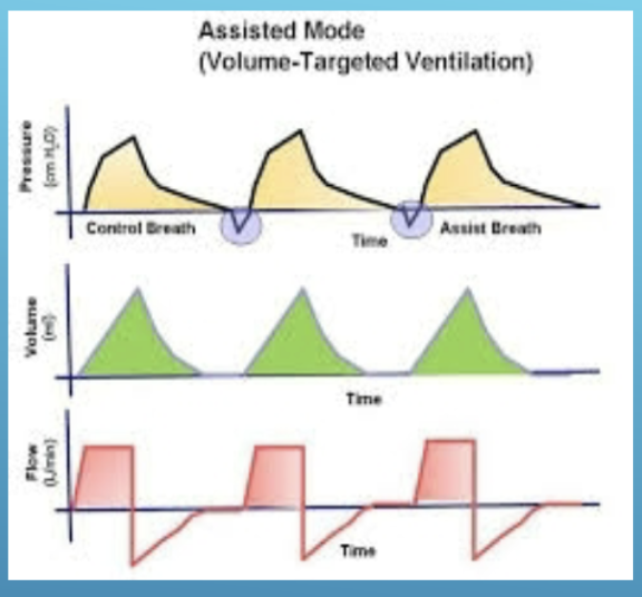
volume control waveforms (flow patterns and shapes)
Flow pattern
constant and square
sinusoidal
Shape:
ascending ramp
descending/descelerating
pressure control
______
pressure remains constant
volume/flow vary
square/ rectangle
higher MAP
better oxygenation
can lead to volutrauma
if not well controlled by tight arm settings
pressure control waveforms (flow patterns and shapes)
square/contant/rectangular
increasing/decreasing exponential
- Flow pattern: flow pattern varies, has a descelerating ramp, exponential - Shape: rectangular

3 phase variables
trigger
limit
cycle
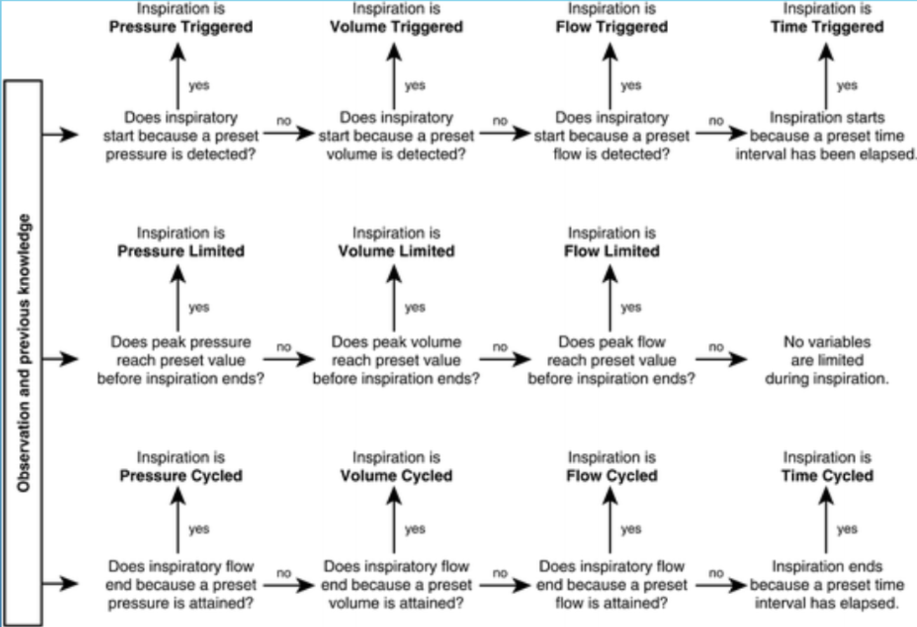
TLC for VC,PC, PS
VC
trigger
patient
flow
pressure
vent
time
limit
volume
cycle
time
PC
trigger
patient
flow
pressure
vent
time
limit
pressure
cycle
time
PS
trigger
patient
flow
pressure
limit
pressure
cycle
flow
AC/VC is volume limited, time cycled and can be machine or patient triggered
AC/PC is pressure limited, time cycled and can be machine or patient triggered
SIMV VC with PS is volume limited on mandatory breaths but pressure limited in patient triggered breaths
This mode is volume limited, time cycled but can be patient or machine triggered
AC/VC
trigger: how breath is triggered, sensitivity setting troubleshooting
How inspiration begins, what starts the inspiratory phase
how to trigger
time
set by RR
use TCT
patient
pressure
cmH2O
flow
COPD
volume

time trigger
ex
VC
use TCT

patient trigger
spontaneous
PS
SIMV
set sensitivity
this is patient effort → set in:
pressure
flow
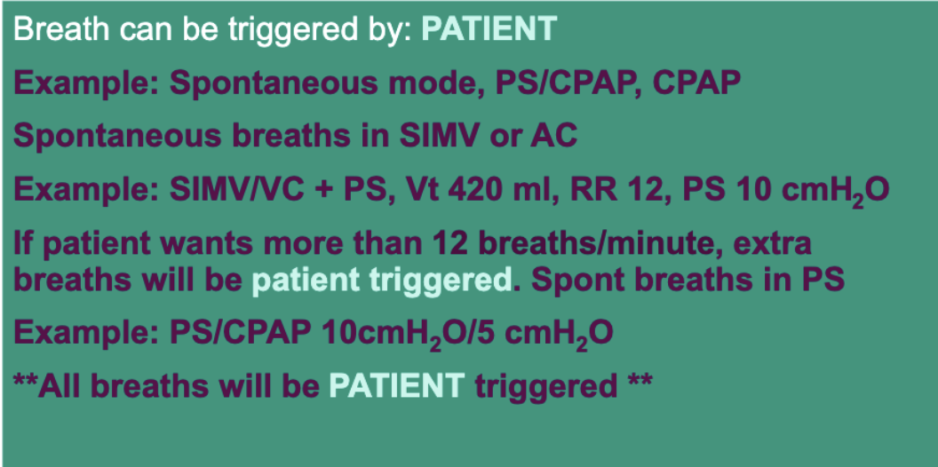
high vs low pressure sensitivity
If pressure sensitivity is set high, it requires
more patient effort
If pressure sensitivity is set low, it requires
less patient effort
-1 to -2 cmH2O common for pressure sensitivity setting
how is flow sensitivity triggered
vent detects a drop of flow in patient circuit during
exhalation
When set properly, flow tends to requires less WOB than pressure sensitivity triggers
high vs low flow sensitivity
more common than pressure sensitivity
If flow sensitivity is set high, it requires
more patient effort
If flow sensitivity is set low, it requires
less patient effort
too low vs too high flow sensitivity
If flow sensitivity is set too low, vent will
auto-trigger
If flow sensitivity is set too high, patient will be
locked out
volume trigger (Often called ‘manual’ breath)
Volume triggering is uncommon
You’ll see this on Drager Babylog and Cardiopulmonary Venturi
There’s also ‘manual’ triggering
where you, the RT, push a button and trigger a breath
Patient is on AC/VC Vt 420 ml, RR 12, FiO2 0.35 PEEP 5 cmH2O. Vent cycles quickly from one breath to the next. Actual RR is 28. The pressure indicator doesn’t change at the beginning of each inspiration. Every breath is either assisted or patient-triggered breath.
Problem?
hiccups
auscultation from heartbeat
water in corrugated tubing
leak
define cycle
How inspiration ends, what ends the inspiratory phase
Cycle variables for modes
VC
time
PC
time
PS
flow
birdmark 7
4 ways to cycle breath
Volume
Pressure
Flow
Time
define time-cycled breaths
the inspiratory phase ends when a predetermined time has elapsed. At that time
the expiratory valve opens and exhaled air is vented out
Tidal volume = flow x Ti
AC/VC is volume-controlled, time cycled, because breath ends after Ti ends and VC = Volume Control(led)
time cycle VC
increases and decreases in compliance do not impact flow pattern or volume. Volume is delivered in a fixed amount of time. Pressure can vary with each breath.
time cycle PC
volume and flow vary. If compliance goes up or down, flow and volume change. AC/PC limits pressure and cycles with time.
This mode can be used to protect the lungs from
high pressures
Alarms must be set carefully to make sure patient gets adequate minute ventilation
Pressure cycle
Inspiration ends in pressure-cycled ventilation when a set pressure is reached at the mouth or upper airway such as a Bird Mark 7
Advantage: Reduces lung damage caused by high pressures (can be LPS – lung protective strategy)
Disadvantage: variable Vt and generally lower Vt when compliance decreases or if airway resistance goes up. Could create volutrauma if compliance improves
pressure-cycling also happens in volume-controlled breaths when pressure exceeds maximum safety high-pressure limit
flow cycle
With flow-cycled ventilation, the vent cycles into the expiratory phase once flow reaches predetermined value during inspiration.
Flow cycling is the most common cycling mechanism
reduces resistance
easier for pt to trigger next breath
continuous gas flow
When the flow reaches a percentage of peak inspiratory flow, exhalation begins, usually 5 – 80%
what is controlled during exhalation
pressure
baseline variable
expiratory retard
creates resistance during exhalation
pursed lip breathing
rarely used
expiratory hold
pause at end of expirations
measures
autopeep
Tells how much air is trapped in the lungs at the end of exhalation
pt must be
passive
no active/spont breaths
inspiratory hold
This inspiratory hold is designed to keep air in the lungs at the end of inhalation, before exhalation valve opens Can also be called inspiratory hold or end-inspiratory pause
Sometimes, this technique is used to increase peripheral distribution of gas and improve oxygenation
But if you increase i-time, you also decrease e-time, so keep it all in perspective
expiratory phase
PERIOD FROM THE END OF INSPIRATION TO THE BEGINNING OF THE NEXT BREATH
End of Ti to the beginning of the next Ti or simply Te
limit variable: time, pressure, flow
Places a maximum on one (or more) of the 4 control variables
volume limit
Inspiration is defined at the beginning of inspiratory flow to the beginning of expiratory flow
Vent can limit variables of volume, time, pressure, or flow
In AC/VC, the volume limit = set tidal volume. In the picture, the Vt was ‘limited’ at 500 ml