IFR checkride notes
 Call Kai
 Learn
 Practice Test
 Spaced Repetition
 Match
 Flashcards
 Knowt Play
1/33

There's no tags or description
Looks like no tags are added yet.
34 Terms
WHEN IS AN INSTRUMENT RATING
REQUIRED?
Within 6 calendar months preceding the month of
flight:
■ 6 instrument approaches.
■ Holding procedures & tasks.
■ Intercepting & Tracking courses through the use of
navigational electronic systems.
■ The above can be completed in a FFS, ATD, or FTD
provided the device represents the category of
aircraft for the instrument rating privileges to be
maintained and the pilot performs the tasks and
iterations in simulated instrument conditions. A
flight instructor is not needed.
To act as PIC under IFR or in weather conditions
less than VFR minimums
Within 6 calendar months preceding the month of
Flight:
■ 6 instrument approaches.
■ Holding procedures & tasks.
■ Intercepting &
■ Tracking courses through the use of
navigational electronic systems.
■ The above can be completed in a FFS, ATD, or FTD
provided the device represents the category of
aircraft for the instrument rating privileges to be
maintained and the pilot performs the tasks and
iterations in simulated instrument conditions. A
flight instructor is not needed.
No “6 HITS” logged looking back six months?
You have an additional 6 months to regain currency by
performing the “6 HITS” with a safety pilot.
■ Safety pilot requirements
▷ Holds at least a private pilot certificate with the
appropriate category and class.
▷ Have adequate vision forward and to each side of
the aircraft.
▷ Aircraft must have a dual control system.
More than 6 months since IFR current?
■ An Instrument Proficiency Check (IPC) is required.
Administered by a CFII, examiner, or other approved
person. Guidelines are in the ACS.
■ Some IPC tasks, but not all, can be conducted in a FTD
or ATD. (See ACS)
To meet recent instrument experience requirements,
the following information must be recorded in the person's
logbook:
■ Location & type of each instrument approach
accomplished, and
■ The name of the safety pilot, if required.

LOGGING INSTRUMENT APPROACH PROCEDURES – REQUIREMENTS
1. You must operate the aircraft, FFS, ATD or FTD solely by reference to instruments. – §61.51(g)(1)
▷ A flight instructor may log an IAP conducted by the student in actual IMC. (See FAA letter to Levy, 2008)
2. Be established on each required segment of the IAP down to its published minimums (MDA or DA).
▷ The Initial (starting at the IAF), Intermediate and Final approach segments are required for logging the
approach, unless:
▷ When radar vectored to final by ATC. (In simulated IMC, vectors from the safety pilot are also accepted).
3. If conducted in simulated IMC in an aircraft, or in a FFS, ATD or FTD, simulated conditions must continue down to
MDA or DA.
4. In an aircraft, flight must be in actual or simulated IMC.
5. In an aircraft, if conditions change from actual IMC to VMC during the final approach segment, you can still log the
approach.
NEED A DESTINATION ALTERNATE?
“1-2-3” RULE
A destination alternate is always required, unless:
■ An instrument approach is published and
available for the destination, AND,
■ For at least 1 hour before to 1 hour after ETA:
▷ Ceiling will be at least 2000’ above airport
elevation; and
▷ Visibility will be at least 3 SM.
IFR fuel requirements
Fuel from departure to arrival airport
+
Fuel from destination to most distant alternate
+
45 minutes calculated from cruise speed
MIN WX CONDITIONS REQUIRED AT AN AIRPORT
TO LIST IT AS AN ALTERNATE - precision vs non, or no instrument approach
Use the alternate airport minima published in the
procedure charts, or, if none:
■ For a Precision approach:
600 ft ceiling and 2 SM visibility.
■ For a Non-precision approach:
800 ft ceiling and 2 SM visibility.
■ If no instrument approach available at the
alternate:
Ceiling & visibility must allow descent from MEA,
approach and landing under VFR.
FILING AN ALTERNATE - GPS CONSIDERATIONS
■ Equipped with a non-WAAS GPS? Flight plan can
be based on GPS approach availability at either the
destination or the alternate, but not at both.
■ WAAS Without baro-VNAV? Flight plan may be
filed based on LNAV or circling minimas at the
alternate (regardless of the available approaches at
the destination).
■ WAAS with baro-VNAV? LNAV/VNAV or RNP 0.3
are allowed as basis for the flight plan’s alternate
(Requires Special Authorization & RNP availability).
Vertical separation hemispherical rule above FL 290
Above FL290 (in non-RVSM)
■ 0o-179o: Flight Levels at 4,000’ intervals starting at FL290 (e.g.
, FL 290, 330, 370)
■ 180o-359o: Flight Levels at 4,000’ intervals starting at FL310
(e.g., FL 310, 350, 390)
FL290-FL410 (in RVSM)
■ 0o-179o: Odd Flight Levels at 2,000’ intervals starting at FL290
(e.g., FL 290, 310, 330)
■ 180o-359o: Even Flight Levels at 2,000’ intervals starting at
FL300 (e.g., FL 300, 320, 340)
IFR takeoff minimums
No T/O minimums mandated for part 91 operations. Part
121, 125, 129, 135:
■ Prescribed T/O minimums for the runway, or, if none:
■ 1-2 engines airplanes: 1 SM visibility
■ More than 2 engines: 1⁄2 SM visibility
(T) Non-Standard TO minimums / Departure Procedures.
(A) Non-Standard IFR alternate minimums exist.
(A NA) Alternate minimums not authorized due to
unmonitored facility or the absence of weather
reporting service.
Two types of Departure Procedures
▷ Obstacle Departure Procedure (ODP)
□ Provides only obstacle clearance.
□ Printed either textually or graphically.
□ Graphic ODPs are titled “(OBSTACLE).”
▷ Standard Instrument Departure (SID)
□ In addition to obstacle clearance it reduces
pilot and controller workload by simplifying
ATC clearances and minimizing radio
communications.
□ May depict special radio failure procedures.
□ SIDs are always printed graphically.
Departure Procedure equipment requirements
▷ Non-RNAV DP - for use by aircraft equipped with
ground-based navigation (i.e., VOR, DME, NDB).
▷ RNAV DP - for aircraft equipped with RNAV
equipment (e.g., GPS, VOR/DME, DME/DME).
Require at least RNAV 1 performance. Identified
with the word “RNAV” in the title.
▷ RADAR DP - ATC radar vectors to an ATS route,
NAVAID, or fix are used after departure. RADAR
DPs are annotated “RADAR REQUIRED.”
DIVERSE DEPARTURE PROCEDURE
■ All US airports with a published IAP but with no
published DP meet the Diverse Airport criteria
■ This criteria requires that an airport has been
evaluated for no obstacles within 200 ft altitude/NM
up to a minimum IFR altitude.
■ Diverse Airport Departures provide obstacle
clearance when a DP is not published.
■ Turns are allowed only after reaching 400 ft AGL.
■ A Diverse Vector Area (DVA) allows ATC to provide
radar vectors instead of an ODP, while meeting the
diverse departure criteria. DVA information is found in
the US terminal procedures publication. It includes a
statement that initial headings are provided by ATC and
any applicable climb gradients.
VISUAL CLIMB OVER AIRPORT (VCOA)
A departure option for IFR aircraft in VMC.
■ The pilot visually conducts climbing turns over the
airport up to the published "climb to" altitude, from
which he proceeds to the instrument portion of the
departure.
■ Designed to avoid obstacles beyond 3 SM from the
departure end of the runway (DER), as an alternative to
complying with climb gradients greater than the
standard 200 ft/NM.
■ Advise ATC as early as possible prior to departure of
the intent to fly a VCOA.
■ Published in the “Take-Of Minimums and (Obstacle)
Departure Procedures” section of the TP.
■ May appear as an option on graphic ODPs
STANDARD TERMINAL ARRIVAL (STAR)
■ Serves as a transition between the enroute structure
and a point from which an approach to landing can
be made.
■ Transition routes connect enroute fixes to the basic
STAR procedure.
■ Usually named according to the fix at which the
basic procedure begins.
■ As with a SID, you can state “NO STARs” in the
remarks section of the flight plan, to avoid getting a
clearance containing a STAR.
■ RNAV STARs require RNAV 1 performance.
MIN IFR ALTITUDES general
Except for takeoff or landing, or otherwise authorized by the FAA, no person may operate an aircraft under
IFR below -
▷ Minimum altitudes prescribed for the flown segment, or if none:
▷ Mountainous areas: 2,000 ft above the highest obstacle within a horizontal distance of 4 NM from the
course.
▷ Non-mountainous areas: 1,000 ft above the highest obstacle within 4 NM from the course.
DA/H, MAA, MCA, MDA/H, MEA, MOCA, MORA, MRA, MTA, MVA, OROCA - definitions
■ DA / H - Decision Altitude / Height: the Altitude (MSL) / Height (above runway threshold), on a vertically guided
instrument approach procedure (ILS, LNAV/VNAV, LPV, etc) at which the pilot must decide whether to continue
the approach or to go around.
■ MAA - Maximum Authorized Altitude. Annotated “MAA-17000” (17,000ft as an example) on IFR charts.
■ MCA - Minimum Crossing Altitude. The lowest altitude at certain fixes that an airplane must cross when flying in
the direction of a higher MEA.
■ MDA / H - Minimum Descent Altitude / Height: The lowest Altitude (MSL) / Height (above runway threshold) to
which descent is authorized on a non-precision approach until the pilot sees the visual references required for
landing.
■ MEA - Minimum Enroute Altitude: The lowest published altitude between radio fixes which assures acceptable
navigational signal coverage and meets obstacle clearance requirements. An MEA gap establishes an area of
loss in navigational coverage and annotated “MEA GAP” on IFR charts.
■ MOCA - Minimum Obstruction Clearance Altitude: Provides obstacle clearance and navigation coverage only up
to 22 NM of the VOR.
If both an MEA and a MOCA are prescribed for a particular route segment, a person may operate an
aircraft lower than the MEA down to, but not below the MOCA, provided the applicable navigation
signals are available. For aircraft using VOR for navigation, this applies only when the aircraft is within
22 NM of the VOR. (§91.177)
■ MORA - Minimum Off Route Altitude (Jeppesen):
Route MORA provides obstruction clearance within 10NM to either side of airway centerlines and within a
10NM radius at the ends of airways.
Grid MORA provide obstruction clearance within a latitude / longitude grid block.
■ MRA - Minimum Reception Altitude. The lowest altitude on an airway segment where intersection can be
determined using radio navigational aids.
■ MTA - Minimum Turning Altitude: Provides vertical and lateral obstacle clearance in turns over certain fixes.
Annotated with the MCA X icon and a note describing the restriction.
■ MVA - Minimum Vectoring Altitude: The lowest altitude at which an IFR aircraft will be vectored by a radar
controller, except as otherwise authorized for radar approaches, departures, and missed approaches. MVAs may
be lower than the minimum altitudes depicted on aeronautical charts, such as MEAs or MOCAs.
■ OROCA - Off Route Obstruction Clearance Altitude: Provides obstruction clearance with a 1,000 ft buffer in non-
mountainous terrain areas and 2,000 ft in mountainous areas. OROCA may not provide navigation or
communication signal coverage.
*Designated mountainous areas are defined in 14 CFR part 95 by lat / long coordinates.

Cruise Clearance
A “cruise clearance,” can be issued by ATC to allocates a block of airspace to the flight. This airspace begins at the
minimum IFR altitude and extends to the altitude (including) specified in the clearance. Within this block, you are
free to climb and descend. However, once you start descending and verbally report leaving an altitude, you may not
return to it without additional ATC clearance.
A cruise clearance also allows you to begin an approach at the destination without receiving an additional “cleared
for approach” clearance.
Example: “N12345 Cruise 6,000’” (compare to “N12345 Maintain 6,000’, where you have to stay at 6,000’)
Block Altitude
A block of altitudes assigned by ATC to allow altitude deviations within it.
Example, “Maintain block altitude 9 to 11 thousand.”
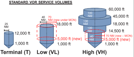
VOR service volumes
VOR receiver checks, limitations, and sign-offs
VOR Receiver Checks (§91.171)
■ Perform every 30 calendar days
▷ VOT ±4o
▷ Repair Station ±4o
▷ VOR ground checkpoint ±4o
▷ VOR airborne checkpoint ±6o
▷ Dual VOR cross-check ±4o
▷ Above a prominent ground
landmark on a selected radial
at least 20 NM from a VOR,
flying at a “reasonable low
altitude” ±6o
VOR limitations
■ Cone of confusion
■ Reverse sensing (if used incorrectly)
■ Requires line-of-sight between aircraft and station.
VOR check sign-off (§91.171)
D.E.P.S –
D - Date
E - Error (bearing error)
P - Place
S - Signature
Glide slope
■ Provides vertical course guidance.
■ Frequencies: 329.3 to 335 MHz (UHF) ,automatically tuned with the localizer.
Vertical position is interpreted by the intensity of 90 and 150 Hz signals carried
over the UHF frequency and directed above and under the slope.
■ Width: 1.4o (full deflection is 0.7o either direction).
■ Range: typically up to 10 NM.
■ Slope: typically 3°.
■ Errors: False glide slope above normal glide slope.

Localizer
Provides lateral course guidance.
■ Frequencies: 108.1 - 111.95 MHz with odd tenths only. 90 and 150 Hz
signals are carried over the VHF frequency and used by the receiver
interpret the aircraft’s lateral position.
■ Width: Between 3°-6° so that the width at the threshold would be 700
feet. Usually 5° total width. (2.5 full deflection to each side, 4 times
more sensitive than a VOR).
■ Coverage range: 35° to each side of the centerline for the first 10NM and 10° up to 18NM from the antenna and
up to an altitude of 4500'.

Marker Beacons
■ Provide range information over specific points
along the approach. Transmits at 75 MHz.
■ Outer marker: 4-7 miles out. Indicate the position at
which the aircraft should intercept the GS at the appropriate interception altitude ±50ft. BLUE. “- - -“
■ Middle marker: ~3500ft from the runway. Indicates the approximate point where the GS meets the decision
height. Usually 200ft above the touchdown zone elevation. AMBER. “. - . -”
■ Inner marker: between the MM and runway threshold. Indicates the point where the glide slope meets the DH on
a CAT II ILS approach. WHITE. “. . .”
■ Back course marker: Indicates the FAF on selected back course approaches. Not part of the ILS approach.
WHITE. “.. ..”

Approach light systems
■ Provides basic visible means to transition between instrument-guided flight into a visual
approach.
■ ALS extends from the landing threshold into the approach area up to:
▷ 2,400-3,000 feet for precision instrument runways, and
▷ 1,400-1,500 feet for non-precision instrument runways.
■ May include Sequenced Flashing Lights, which appear to the pilot as a ball of light traveling towards the
runway at twice a second (AKA “The Rabbit”).
■ The visible parts of the ALS configuration can help the pilot estimate flight visibility.
ILS categories

Area navigation (RNAV)
■ Allows navigation on any desired path without the need to overfly ground-based facilities.
■ Types:
▷ Global Navigation Satellite System (GNSS) (e.g., GPS, Galileo, GLONASS, BeiDou)
▷ VOR/DME RNAV
▷ DME/DME RNAV
▷ Inertial Reference Unit / System (IRU/ IRS)
■ RNAV VNAV - Vertical NAVigation guidance.
■ BARO-VNAV - An RNAV system that uses the barometric altitude to compute vertical guidance for the pilot.
■ Published RNAV routes include Q (FL180 to FL450) and T (1,200 AGL to 18,000 MSL) routes and are designated
RNAV 2 unless charted as RNAV 1.
■ Magnetic Reference Bearing (MRB) - the published bearing between two waypoints on an RNAV route.
GPS basics
■ GPS is a Global Navigation Satellite System (GNSS) operated by the United States.
■ The constellation consists of a minimum of 24 satellites (with some spares) orbiting above the earth at 10,900
NM. The system is designed so that at least 5 satellites are in view at any given location on earth.
■ The Aircraft’s GPS receiver calculates the distance to a GPS satellite based on the time lapse since the
broadcast timestamp (obtained from an atomic clock onboard the satellite) and the time it received the signal.
■ Using only one satellite, the aircraft could virtually be on any point on a sphere surrounding the satellite, with the
calculated distance (“pseudo-range”) as the sphere’s radius.
■ The GPS receiver uses the intersection of spheres, from multiple satellites, to calculate the aircraft’s
geographical position. Course and speed data are computed from aircraft position changes.
■ At least 3 satellites are required for 2D position. (latitude and longitude); at least 4 satellites are required for
3D position. (latitude, longitude and altitude).
Receiver Autonomous Integrity Monitoring (RAIM)
(RAIM) is a function of GPS receivers that monitors the integrity of
the satellite signals.
▷ RAIM (fault detection) requires a minimum of 5 satellites, or, 4 satellites + an altimeter input (baro-aided
RAIM)
▷ To eliminate a corrupt satellite (fault exclusion), RAIM needs an additional satellite (total of 6 or 5 + baro-aid)
■ A database loaded into the receiver unit contains navigational data such as: airports, navaids, routes, waypoints
and instrument procedures.
■ Airborne GPS units use great-circle navigation.
■ GPS CDI deflection shows distance, unlike a VOR’s CDI, which presents an angular distance off course in
degrees.
■ GPS can substitute ADF or DME, except for ADF substitution on NDB approaches without a GPS overlay (“or
GPS” in title).
■ Check GPS NOTAMS before the flight and use RAIM prediction if available on your receiver.
GPS Augmentation systems, or Differential GPS (DGPS)
Improves the accuracy of GPS by measuring
errors received by reference stations at known geographical locations and then broadcasting those errors to
supported GPS receivers.
▷ Satellite Based Augmentation System (SBAS)
□ Wide Area Augmentation System (WAAS) in the US; EGNOS in Europe.
□ Ground stations (Wide-area Reference Stations and Wide-area Master Stations) measure GPS errors and
produce correction signals. These corrections are broadcasted back to the satellite segment from which
they are bounced back to aircraft GPS WAAS receivers to improve accuracy, integrity and availability
monitoring for GPS navigation.
□ Covers a wide area.
□ Facilitates APV approaches such as LPV and LNAV/VNAV and non-precision LP approaches.
▷ Ground Based Augmentation System (GBAS)
□ Formerly named Local Area Augmentation System (LAAS) in the US. Now replaced with the ICAO term
“GBAS.”
□ Errors are broadcasted via VHF to GBAS-enabled GPS receivers.
□ GBAS is more accurate than WAAS but covers a much smaller geographical area.
□ Allows for category I and above approaches to GLS DA minima.
REQUIRED NAVIGATION PERFORMANCE (RNP)
■ RNP is:
▷ A statement of navigation equipment and service performance.
▷ RNAV with navigation monitoring and alerting.
■ All RNAV approaches are RNP approaches
▷ Most US RNP approaches are titled “RNAV (GPS)”.
▷ US Approaches with “RNAV (RNP)” in the title are “AR” (Authorization Required) approaches, which
require special FAA approval for the crew, aircraft and operation.
▷ In other countries, all RNP approaches may have “RNP” in the title, even those that do not require
special authorization.
RNP approach minima and equipment:
■ GLS DA minima using GBAS (formerly LAAS)
■ LP MDA or LPV DA minima require RNP achieved by WAAS.
■ LNAV / VNAV DA achieved by VNAV-approved WAAS, or BARO-VNAV systems.
■ LNAV MDA - achieved by a basic, unaugmented IFR-approved GPS.
■ Area Navigation (RNAV)
RNAV is a system that enables navigation between any two points without the need to overfly ground-based stations.
■ GNSS is a broad term for satellite-based RNAV systems.
GPS is the GNSS operated by the USA. Other examples are GLONASS by Russia and Galileo by the EU.
■ Performance Based Navigation (PBN)
PBN is a general basis for navigation equipment standards, in terms of accuracy, integrity, continuity, availability and
functionality for specific operation contexts (e.g., final approach, enroute, missed approach).
■ Required Navigation Performance (RNP)
RNP is a specific statement of PBN for the flight segment and aircraft capability.
RNP is also defined as RNAV + navigation monitoring and alerting functionality
- Receiver Autonomous Integrity Monitoring (RAIM) or built-in monitoring in WAAS provide this capability.
Enroute – RNP 2.0 (2 NM accuracy 95% of the flight time)
Terminal & Departure – RNP 1.0 (1 NM accuracy 95% of the flight time)
Final Approach – RNP 0.3 (0.3 NM accuracy 95% of flight time)
Advanced RNP (A-RNP) - a higher RNP standard mandatory for RNP AR, that require capability for: (AIM 1-2-
2)
Radius-to-Fix (RF) legs
Scalable RNP - can gradually vary between 1.0 and 0.3 (or as low as 0.1) RNP values, and
Parallel offset flight path generation