Unit Ops 3 Exam 2 - Lecture 6
 Call Kai
 Learn
 Practice Test
 Spaced Repetition
 Match
 Flashcards
 Knowt Play
1/32

Earn XP
Description and Tags
Flow and Temperature Measurement
33 Terms
Thermocouple
A temperature measurement device consisting of a junction of wires made of two different metals

Thermocouple types and code
Code: ANSI (USA), IEC (elsewhere)
J (black)
K (yellow)
T (blue)
E (pink)
N (orange)
Seebeck coefficient
slope of the measured voltage versus temperature
not a constant
dependent on thermocouple type
Resistance thermometer / Resistance temperature detector (RTD)
Pros over thermocouples:
more accurate
more repeatable
Cons:
slower response time
less durable
more expensive (3x)
narrower temperature range
less common in industry

Platinum resistance thermometer (PRT)
Most common type of RTD
Advantages:
excellent corrosion resistance
widest useful temperature range
stable reading over time
linear temperature vs. resistance
suitable temperature coefficient of resistance (changes enough to read differences)

RTD vs. Thermistor
RTDs use metal
Thermistors use metal oxides
Thermistors may be NTC or PTC
All RTDs are PTC
Negative temperature coefficient (NTC)
May be used as a temperature sensor or as an inrush current limiter
Thermistors
Positive temperature coefficient (PTC)
May be used as a current limiter (resettable fuse). Used in flowmeters
RTDs and thermistors
Temperature measurement compatibility
Thermocouples, RTDs, thermistors, and their wiring are NOT interchangable
RTDs and thermistors require a current source
Thermocouples have a polarity which must be followed and require matching type thermocouple wire all the way to the receiving instrument (wires connected to must match wires inside)
Flowmeters key parameters
required accuracy
phase
temperature and pressure
lubricity
entrained solids/particles
density
viscosity
chemical properties
presence of multi-phases
abrasiveness
rangeability
Rangeability
Also called turndown ratio
highest flowrate measured with acceptable accuracy divided by lowest flowrate measured with acceptable accuracy, expressed as a ratio
If a flowmeter has a useful range from 1 gpm to 10 gpm, the rangeability is 10:1
Positive displacement flowmeters
gear
oval gear
rotary vane
rotary piston
rotary abutment
Non-PD flowmeters
differential pressure flowmeters (orifice, nozzle, venturi, pitot tube)
turbine
electromagnetic
ultrasonic
oscillating
target
thermal mass
coriolis
rotameter
hot wire / hot film anemometer
Gear flowmeter
Liquid enters, is carried around the outside of the gear in the spaces between the teeth, and exits
Measures gear speed

Oval gear flowmeter
Works just about the same as the gear
small flowmeter —> small flowrates

Rotary vane flowmeter
Measures how fast the rotor goes around
Fluid enters, fills space between vanes, transported around the circumference of the housing, exits

Rotary abutment flowmeter
Center rotor rotates in the opposite direction of the other two (displacement rotors)
Low pressure drop
compatible with high viscosity fluids
rotors are kept in sync by a timing gear
gravity driven flows
measure dispensed volume
Displacement rotors do not touch the housing, no friction
identify by triangular shape

Differential pressure flowmeters
Any gain in KE a fluid may acrue due to its increased velocity through a constriction is balanced by a drop in pressure (Bernoulli’s principle)
Orifice, nozzle, venturi, pitot tube

Orifice flowmeter
Highest friction loss
Speeds up through the decreases area, P decreases
Worst rangeability

Nozzle flowmeter
Medium friction loss
Works the same as orifice, but more gradient change in diameter and lower pressure drop

Venturi flowmeter
lowest friction loss
more gradual increase/decrease in diameter
lowest pressure drop

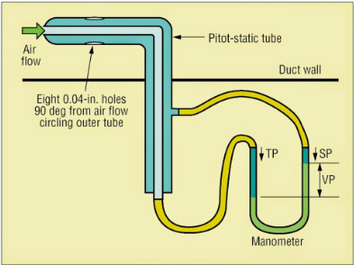
Pitot tube
Differential pressure measured from perpendicular holes
Most common in HVAC and airplanes (portable)
Turbine and paddlewheel flowmeters
use a rotating turbine / paddlewheel with a magnetic sensor to detect the speed of rotation
Paddlewheels may be reversible
Turbines are typically not reversible
The paddle axis is perpendicular to flow
The speed it spins is related to flowrate
Paddle is not sealed therefore not positive displacement

Electromagnetic flowmeters
No moving parts
highest turndown ratio (rangeability)
expensive
fluid must be conductive
uses Faraday’s law of electromagnetic induction
Voltage measured from separation of charges, greater separation, greater voltage, greater velocity (V proportional to v)
Constant magnetic field from coils

Ultrasonic flowmeter
an ultrasonic bean goes first from the downstream transducer to the upstream transducer
The transmission is then sent from the upstream transducer to the downstream transducer
The ultrasound is accelerated slightly by the velocity of the fluid through the pipe
T1-T2 (times) is directly proportional to the liquid flow velocity
Portable, easily retrofitted
pricey

Oscillatory flowmeters
Suitable for both liquids and gases
Fluidic and vortex shedding

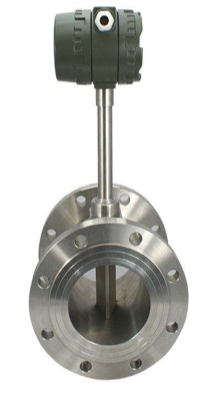
Vortex shedding flowmeter
Vortex shedding is caused by fluid flowing around an object (bluff body) placed in the flowing stream
The frequency of the vortices is measured
V_dot = k*d*f(frequency)
The frequency is directly proportional to the volumetric flowrate
Vortices are measured by high frequency pressure transducers, measuring variations in heat transfer from a heated resistor, or ultrasonics

Fluidic flowmeter
Fluid entering flows along one interior wall
Some fluid is diverted back to the inlet (feedback flow) causing the fluid to be pushed against the other wall
Flow shifts from side to side, creating oscillations
Oscillations sensed by an electrically heater thermistor on one side
Alternating flow causes the thermistor to be cooled, this signal is directly proportional to velocity

Target flowmeter
an object (target) is placed in the fluid flow, mounted at a right angle
force exerted on the target is measured by strain gauges, which produce electronic output that is proportional to the square of the flow rate
Optimum size of target depends on the liquid

Thermal mass flowmeter
Only for gases (N2 commonly)
two windings on the sensor tube are heated
when flow takes place, gas caries heat from the upstream to the downstream windings, resulting in a temperature difference, and their resistances change accordingly
The difference in resistance is proportional to flowrate and is measured using a circuit called a wheatstone bridge
Turbulence filter laminarizes flow
gas picks up heat from first winding and picks up less heat from second winding since it’s already heated
Temperature-dependent different in resistance is linearly proportional to mass flow rate
Flowmeter reports volumetric flowrate by converting internally assuming STP (typically wrong)

Coriolis flowmeter
Dual parallel tubes
no flow = in phase
flow = coriolis forces, phase shift, asynchronoous
delta t (phase shift) is proportional to mass flow rate
density is propotional to inverse of frequency squared
calculate V_dot from density and mass flow

Rotameter
Variable area flowmeter
Mechanical
force balance on float
Typically read at the widest point of the float
Narrower at bottom, wider at top
drag force = gravitational force
velocity decreases as area increases, float stops where velocity is equal to terminal velocity

Highest and lowest rangeability
Lowest - differential pressure flowmeters
Highest - electromagentic