Naval Engineering: Propulsion, Auxiliary Systems, Hull Structures, and Nuclear Power
 Call Kai
 Learn
 Practice Test
 Spaced Repetition
 Match
 Flashcards
 Knowt Play
1/99

Earn XP
Description and Tags
Comprehensive vocabulary review flashcards covering U.S. Navy diesel engines, gas turbines, propulsion shafting, ship hull mechanics, auxiliary compressed air and desalination systems, and naval nuclear reactor theory.
100 Terms
What are the primary fleet applications of diesel engines in the U.S. Navy?
smaller surface vessels and Emergency/Auxiliary Generators.
What are the primary functions of the piston and crankshaft in a diesel engine?
The piston receives the linear force of expanding combustion gases, and the crankshaft converts into rotary motion to drive the propeller shaft or generator.

What are the four steps of a four-stroke diesel engine operating cycle?
Intake: Piston moves down, drawing air into the cylinder.
Compression: Piston moves up, compressing air to high pressure/temperature.
Power: Fuel is injected and ignites; expanding gases drive piston down.
Exhaust: Piston moves up, forcing burned gases out.

Four-Stroke Diesel Engine (Advantages)
higher thermal efficiency
lower thermal stress on components
complete exhaust scavenging
lower oil consumption

4 Stroke Diesel Cycle Thermodynamic P-v diagram
Process 1 → 2: Isentropic Compression
Process 2 → 3: Constant Pressure (Isobaric) Heat Addition (Q_{in})
Process 3 → 4: Isentropic Expansion (Power Stroke)
Process 4 → 1: Constant Volume (Isochoric) Heat Rejection (Q_{out})

Two-Stroke Diesel Cycle
intake/scavenging and compression on the upstroke
power and exhaust release on the downstroke.

Two-Stroke Diesel Engine (Advantages)
higher power-to-weight ratio
higher power to displacement ratio
and simpler
Diesel Engine Supporting Systems
Fuel System (filters, pressurizes, and atomizes fuel)
Lube Oil System (reduces friction, cools, and cleans)
Cooling Water System (removes excess heat via fresh water/seawater loops)
Air Intake/Exhaust System (supplies clean air and expels combustion gases)
Starting System (cranks the engine using compressed air or electric starters)
Gas Turbine Engines (Fleet Applications)
cruisers (CG-47)
destroyers (DDG-51)
amphibious assault ships (LHA/LHD)
electric power generation via Ship Service Gas Turbine Generators (SSGTGs)
Gas Turbine Engines (Advantages and Disadvantages)
Advantages: Disadvantages:
high power-to-weight ratio high fuel consumption at low speeds
rapid startup time high exhaust heat signature
low vibration, large intake/exhaust ducting
modular maintenance
What are the three basic components of a gas turbine engine?
Compressor
Combustion Chamber (Combustor)
Turbine
Gas Turbine Compressor Purpose?
draws in ambient air and compresses it to high pressure before entering the combustion chamber.

Axial Compressor
Gas turbine compressor where air flows parallel to the rotor shaft
higher mass flow rates
efficiency for high-power naval applications.

Centrifugal Compressor
Gas turbine compressor where air is thrown radially outward, featuring a simpler, robust construction used in smaller turbines and auxiliary systems.
Why use Variable Stator Vanes (VSVs) Variable Vane control?
regulate airflow angles during non-design speeds
-prevent aerodynamic stall and compressor surge (gas reverses direction).
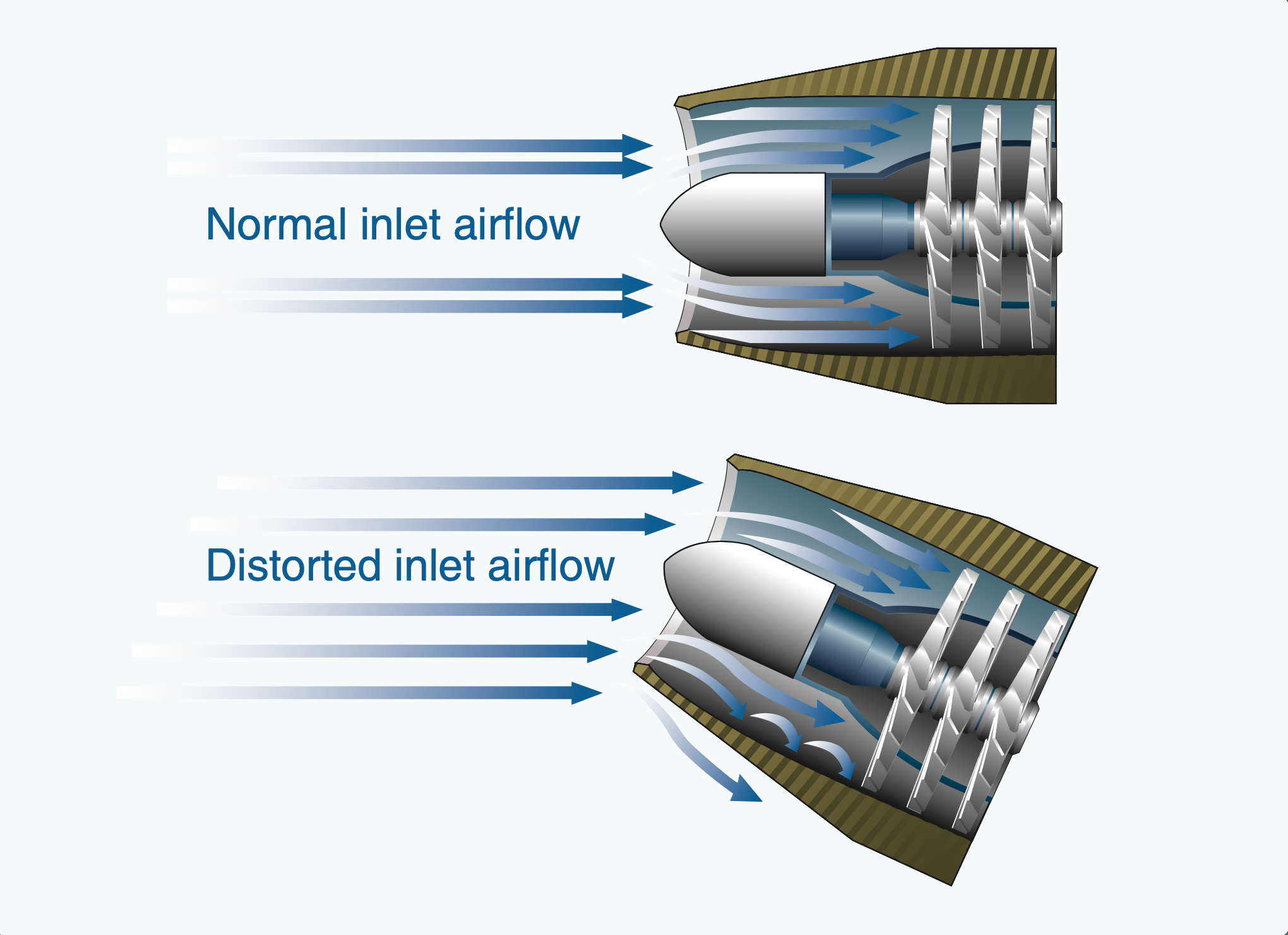
Compressor Stall
The breakdown of smooth airflow over compressor blades caused by an excessive angle of attack,
resulting in a reduced pressure ratio, reverse airflow (surge), and potential engine damage.
How is high pressure air used (Gas Turbine)
anti-icing
acoustic noise reduction
pneumatic starter air for other turbines
cabin pressurization
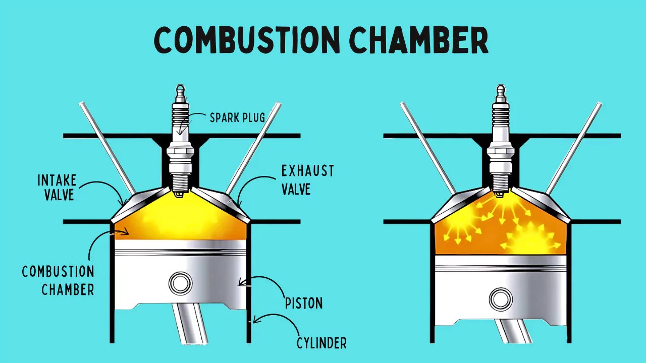
Combustion Chamber (Combustor)
mixes high-pressure air with fuel and ignites it at constant pressure
Types: Can, Annular, and Cannular (Can-Annular) designs.
How is fuel ignited in a gas turbine combustion chamber?
high energy electric spark igniters
once self-sustaining combustion is established, igniters turn off and continuous combustion is maintained.

Turbine Purpose? (Gas Turbine)
extracts thermal energy from expanding hot combustion gases and converts it into rotational mechanical energy to drive the compressor and the output power load.

Single-Shaft Gas Turbine
Gas turbine configuration where the compressor, turbine stages, and driven load are all mounted on one continuous shaft (common in Ship Service Gas Turbine Generators).

Split-Shaft Gas Turbine
Gas turbine design where a gas generator turbine drives the compressor on one shaft, while expanding exhaust gas independently drives a free power turbine coupled to the ship's propeller shaft.

Gas Turbine Support Systems
synthetic lube oil (supplies oil to reduce friction)
exhaust system (expels gases and reduces noise)
pneumatic starting (rotates compressor up using air)
fire extinguishing (Halon/CO2) systems
Gas Turbine Air Intake Filtration How and Why
utilizing moisture separators and high-efficiency particulate filters to remove salt spray, dust, and debris
preventing compressor fouling and hot-section corrosion.
Gas Turbine Heat & Noise Concern & Mitigation
Heat: Use BLISS eductors and cooling fans to suppress
infrared thermal signatures and protect topside materials
Noise: alongside silencers, acoustic enclosures, and ear protection
to protect ears & location
Gas Turbine Starting System
Starting mechanism (pneumatic air starter or hydraulic motor) that rotates the compressor up to self-sustaining speed before fuel ignition and self-acceleration occur.

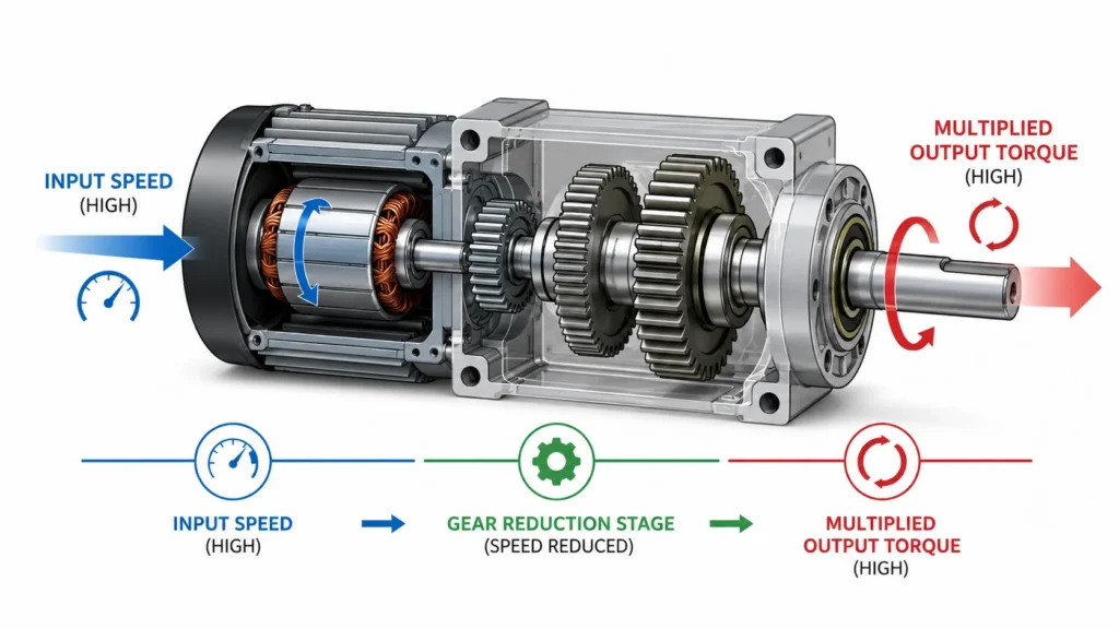
Power Transmission System What Works & Purpose?
Works SSS Clutch and Main Reduction Gears
reduces speed and multiplies torque to be efficient at high speeds.

Brayton Cycle
The ideal thermodynamic cycle governing gas turbine operation
Process 1 → 2: Isentropic Compression (Compressor)
Process 2 → 3: Constant Pressure (Isobaric) Heat Addition (Combustion Chamber)
Process 3 → 4: Isentropic Expansion (Power / Compressor Turbine)
Process 4 → 1: Constant Pressure (Isobaric) Heat Rejection (Atmospheric Exhaust)

General Electric LM2500
Marine-adapted, aero-derivative, split-shaft gas turbine utilized as the primary main propulsion engine for U.S. Navy surface combatants.
Allison 501 GTG
Ship Service Gas Turbine Generator (SSGTG) unit (501-K17/K34) used to produce electrical power 2500 kW to 3000 kW per unit.
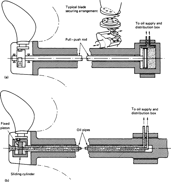
Controllable Reversible Pitch (CRP) Propeller How does it Work? Why?
hydraulic oil pressure passing through the propulsion shaft actuates mechanical linkages in the hub to rotate the blades.
altering pitch and thrust direction without changing shaft rotational direction.
Full Power Lineup
Propulsion plant lineup operating 2 turbines per shaft on 2 shafts (4 turbines operating total), capable of maximum ship speeds exceeding 30 knots.
Split Plant Lineup
Propulsion plant lineup operating 1 turbine per shaft on 2 shafts (2 turbines operating total), providing independent propulsion capability up to approximately 30 knots.
Trail Shaft Lineup
Fuel-efficient plant lineup operating 1 turbine on 1 shaft while the other shaft is unpowered and windmilling, yielding maximum fuel economy for speeds up to approximately 19 knots.
Main Reduction Gear Purpose & Classification
Reduces the high rotational speed from turbine to propeller with power inputs increasing torque
(DDLDA) dual-input, double-reduction, locked-train, double-helical, and articulated.

Synchronous Self-Shifting (SSS) Clutch
Overrunning clutch mechanism that engages automatically when input shaft speed attempts to overtake output shaft speed, and disengages automatically when input speed drops below output speed.
Keeps input shaft speed higher then output.

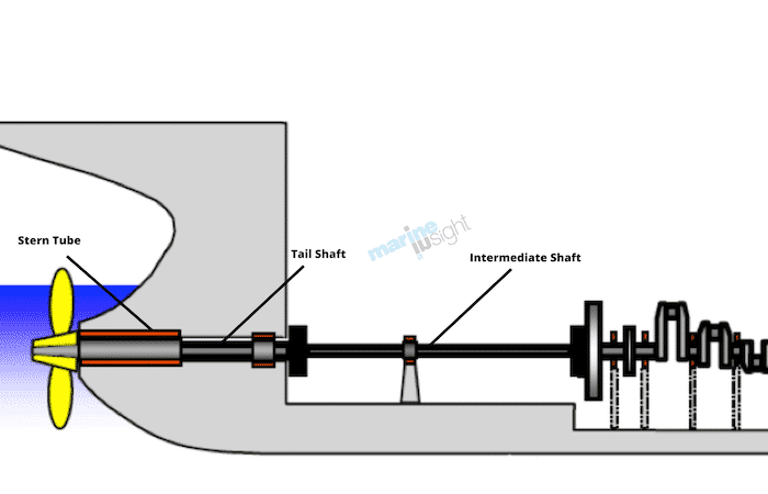
Propulsion Shafting Sections
1. Thrust Shaft
2. Line Shaft
3. Stern Tube Shaft
4. Tail Shaft
Thrust Bearing
Absorb axial thrust generated by the propeller and transfer that force directly to the ship's hull structure to drive the vessel forward or backward.

Journal Bearings (Line Shaft Bearings)
Support the radial weight of the propulsion shafting and maintain proper radial alignment.

Strut Bearings
Bearings that support the external portion of the propulsion shaft near the propeller outside the hull; lubricated and cooled by seawater.

Stern Tube
A watertight passage housing bearings and seals where the rotating propulsion shaft penetrates the hull below the waterline, preventing seawater intrusion.
Fixed-Pitch Propeller vs. Controllable-Pitch Propeller
Fixed-pitch propeller blades are permanently cast to the hub (requiring shaft rotation reversal for reverse thrust),
Controllable-pitch propeller blades pivot dynamically on the hub to alter thrust direction.
Right-Handed vs. Left-Handed Propeller
When viewed from astern looking forward,
right-handed propeller rotates clockwise to produce forward thrust,
left-handed propeller rotates counter-clockwise to produce forward thrust.

Propeller Cavitation
The formation and violent collapse of vapor bubbles on propeller blades when water pressure drops below vapor pressure
causing blade erosion, acoustic noise, severe vibration, and lost efficiency.

Propulsion Lubrication Oil System Purpose?
delivers clean, cooled oil under pressure to bearings and gears to
reduce friction
prevent metal-to-metal contact
remove heat
flush away wear particles
How is Lube oil Purified?
Using centrifugal lube oil purifiers (deLaval type)
spins lubricating oil at high speed to separate out water, sludge, and solid particulates based on density differences.
Propulsion Lube Oil Safety Hazards
Operational risks including high-pressure oil leaks near hot surfaces creating atomized oil mist fire hazard, and loss of lube oil pressure causing rapid catastrophic gear and bearing destruction.
Seaworthiness
The ability of a vessel to safely navigate severe weather, rough seas, and hostile environments while maintaining stability and buoyancy.
Structural Integrity
The capacity of a ship's hull structure to withstand
global static/dynamic wave loads,
localized stresses,
combat shock
Operational Employment (Warship Design)
designing the vessel specifically around its intended
mission roles,
weapon system loadouts,
speed/endurance requirements,
crew capacity.
Stress (σ)
The internal resisting force per unit cross-sectional area (Force/Area) induced inside a material under applied loading.
Strain (ϵ)
The fractional deformation or normalized change in length (ΔL/L0) resulting from applied stress.
Ship Sagging
Hull condition occurring when a wave crest supports the bow and stern while the trough is amidships, subjecting the main deck to compression and the keel to tension.

Ship Hogging
Hull condition occurring when a wave crest supports the ship amidships while troughs are at the bow and stern, subjecting the main deck to tension and the keel to compression.

Warship Hull Structural Components
Primary structural elements comprising the
Keel (principal longitudinal backbone),
Frames (transverse ribs),
Bulkheads (vertical dividing walls),
Doors (watertight bulkhead closures), and Hatches (watertight deck closures).
Compartment Number Designation 3-150-2-L
deck level (3 = 3rd deck below main deck),
forward frame boundary (150 = frame 150),
side relative to centerline (2 = even number, port side),
usage (L = living space).

Submarine Pressure Hull Design
Cylindrical high-strength steel or titanium hull designed to withstand deep-sea hydrostatic crushing pressure, integrated with ballast tanks for neutral buoyancy control and closed-atmosphere environmental control systems.
Compressed Air Systems (Naval Uses)
Shipboard air applications including
diesel and gas turbine starting,
pneumatic valve control,
charging missile launcher tubes, torpedo ejection,
pneumatic tools,
submarine ballast tank blowing.
Positive Displacement vs. Non-Positive Displacement Air Compressors
Positive displacement compressors trap a fixed volume of air and mechanically reduce its volume (e.g., reciprocating piston, rotary screw),
Non-positive displacement compressors use high-velocity rotating impellers to impart kinetic energy that converts to pressure (e.g., centrifugal blowers).

Staging (Compressed air systems)
Number of distinct compression steps used to raise intake air to final discharge pressure.
Single stage: one stage low pressure applications
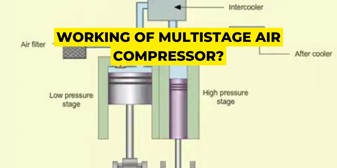
Multi-stage: 2+ stages where air is
partially compressed in a low-pressure stage
passed through an intercooler to remove hear
directed to higher pressure stages to achieve output pressure
Types of Drive Systems?
The prime mover:
almost all are electric motors (rotational power from the ship's electrical grid)
can be internal combustion engines diesel & steam/gas turbines (emergency)
Naval Compressed Air Pressure Ranges
Low Pressure (LP) at <150 psig,
Medium Pressure (MP) at 151 to 1000 psig,
High Pressure (HP) at >1000 psig (typically 3000 to 4500 psig).
Capacity (cubic feet per minute)
volume of air compressed and delivered
LPAC (Low-Pressure Air Compressor) 200CFM for service air
HPAC (High-Pressure Air Compressor) 15-20CFM vital systems:
weapons & diesel starting
Bleed Air
compressed air that is extracted ("bled") directly from the compressor stages of a gas turbine engine (such as the LM2500) before it enters the combustion chamber to burn with fuel
from the high-pressure air produced during the compression phase of the Brayton cycle
used for auxiliary systems: Anti-icing, Prairie Masker Systems, Engine starting, Service air
Cooling
Intercoolers: between stages of a multi-stage compressor thatextracts heat of compression to reduce compression work, improve volumetric efficiency, and keep operating temperatures safe.
Fresh Water & Cooling fans: cools most shipboard compressors
Aftercoolers: heat exchangers located after final discharge stage

Air Receivers (Accumulators)
Pressure storage reservoirs in compressed air systems that absorb compressor discharge pulsations, satisfy peak demand surges, and allow moisture and oil vapor to condense and settle.
Lubrication What is used? Safety Concern?
Lubricating oils & Synthetic Oils
rapid air compression creates high temperatures. lube oil in the compression chamber vaporizes and create an oil-air vapor mist which can mix with high temp & pressure to auto ignite Diesel Effect.
Control Systems
Start/Stop control (Automatically starts the compressor motor when system air pressure drops to a preset lower limit)
Constant Speed (motor running continuously at a constant speed)
Speed Pressure Governing: Regulates and varies the operational speed of the prime mover or compressor in response to real-time air demand
Automatic Shutdowns: Acts as a vital safety system by automatically tripping and stopping the compressor
Compressor Unloading System
Mechanism that vents internal cylinder pressure during startup to allow the compressor motor to reach operating speed without load
preventing motor overload and starting current spikes.

Compressed Air Drying Methods
Dehydration techniques utilizing desiccant air dryers and refrigerated air dryers to remove moisture
preventing internal pipe corrosion, valve sticking, and pneumatic line freezing.
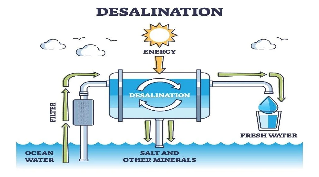
Desalination Principles
The conversion of seawater into fresh pure water (distillate) by thermal evaporation and condensation or pressure-driven membrane filtration, discarding concentrated brine overboard.
What basic principles govern shipboard desalination plants?
converts seawater into fresh pure water (distillate) by thermal evaporation/condensation or by pressure-driven membrane filtration, discarding concentrated brine overboard.
Flash-Type Distilling Plant
seawater enters a vacuum chamber maintained at a pressure lower than saturation pressure (P<Psat), causing a portion of water to instantaneously flash into steam without boiling on heating tubes.
large steam powered ships
HIgh capacity
Cons: Steam dependent and complex plants

Multi-Stage Flash Distilling Unit Paths
Fluid circulation paths where the Feed Path preheats seawater through condenser tubes into flash chambers (discharging brine via loop seals overboard), while the Distillate Path condenses flashed vapor onto cooling tubes, collecting it in troughs for potable water tanks.
Vertical Basket Distilling Plant
Used on Submarines
passes through the distillate cooler, distillate condensers, and air ejector condenser enters the evaporator chamber seawater receives heat from the vertical steam basket and begins to boil, while concentrated unevaporated brine is continuously pumped overboard
Medium output, uses aux steam, high quality
mineral scaling over time, less then flash, need aux steam
Vapor-Compression Distilling Plant
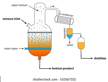
electric ran seawater boils in an evaporator and generated steam is mechanically compressed, elevating its pressure and saturation temperature so condensing steam transfers latent heat back to boil incoming seawater.
used on non steam ships (diesel) low output
high thermal efficient, is mech complex, and uses electric power

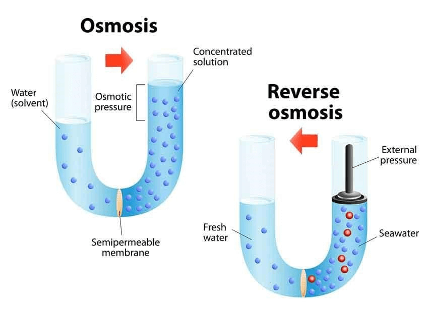
Reverse Osmosis (RO) Desalination
Membrane separation process where high-pressure pumps force seawater against semi-permeable membranes at pressures exceeding natural osmotic pressure (>800–1000 psi), forcing pure water molecules through while retaining salts.
used as primary fresh water production
medium-high output, high efficiency, clean drinking water, instant
not high enough quality for nuclear, weapon systems, membrane degrades, high pressure danger
Salinity Cell
In-line monitoring instrument that continuously detects chloride levels in distillate, automatically dumping water overboard if salinity exceeds allowable limits (typically >0.065 epm).
remote operation where solenoid valves auto dump
Water Safety
conserve limited fresh water (Navy showers)
Secured distilling (pollution in intake, stealth)
at least 10nm from shore
Treatment (chlorine or bromine for potable)
Monitoring (salinity cells on coolers, condensers, feed heat, air ejector)
Admiral Hyman G. Rickover and Early Nuclear Vessels
Admiral Rickover is recognized as the "Father of the Nuclear Navy"; under his leadership, the USS Nautilus (SSN-571) was developed as the first nuclear submarine and USS Enterprise (CVN-65) as the first nuclear aircraft carrier.
Naval Nuclear Propulsion Advantages
Immense energy density (1 g of 235U≈3 tons of coal) enabling nearly unlimited vessel cruising range and continuous high-speed submarine submerged operation without atmospheric oxygen.
Nuclear Isotopic Notation
Standard nuclear representation ZAX, where Z is the atomic number (number of protons) and A is the mass number (total number of protons plus neutrons).
Forces Governing Nuclear Stability
The balance between the short-range attractive Strong Nuclear Force holding nucleons together and the electrostatic repulsive Coulomb Force between protons, requiring an optimal neutron-to-proton (N/P) ratio.
Alpha Decay (α)
Radioactive decay involving the emission of a helium nucleus (24He) according to ZAX→Z−2A−4Y+24He; stopped by skin or paper, but poses a severe internal radiological hazard if inhaled or ingested.
Beta Decay (β−)
Radioactive decay where a neutron decays into a proton, emitting an electron (−10e) and an antineutrino via ZAX→Z+1AY+−10e+νˉe; penetrates skin/tissue and is shielded by thin aluminum or plastic.
Gamma Radiation (γ)
High-energy electromagnetic photon emission from an excited nucleus (ZAX∗→ZAX+γ); highly penetrating whole-body radiation requiring dense lead or steel shielding.
Radioactive Half-Life (t1/2)
The time required for half of the radioactive atoms in a given radioactive sample to undergo spontaneous decay.
Mass Defect (Δm) and Binding Energy (BE)
Mass defect is the difference between total individual nucleon mass and bound nucleus mass; it converts directly to nuclear binding energy via Einstein's equation: BE=Δmc2.
Binding Energy per Nucleon (BE/A) Curve
Stability curve indicating peak nuclear stability around Iron (56Fe); fusing light nuclei lighter than 56Fe releases energy, and splitting heavy nuclei heavier than 56Fe (e.g., 235U) releases energy.
Fast Neutrons vs. Thermal Neutrons
Fast neutrons are released by fission at high energies (∼2 MeV), whereas thermal neutrons are slowed to thermal equilibrium (∼0.025 eV); thermal neutrons have a vastly higher probability (cross-section) of causing 235U fission.
Neutron Moderator
Reactor medium that slows fast neutrons down to thermal energies via elastic collisions; the U.S. Navy uses light water (H2O) because Hydrogen has a mass nearly equal to a neutron, providing efficient moderation and inherent safety.
Free Neutron Nuclear Interactions
The four primary physical interactions occurring between a free neutron and a nucleus:
1. Scattering (Elastic or Inelastic),
2. Absorption,
3. Fission,
4. Radiative Capture.
Uranium-235 Thermal Fission Equation
The representative nuclear fission reaction: 01n+92235U→92236U∗→Fission Fragments+2.501n+Energy (∼200 MeV).
Effective Neutron Multiplication Factor (Keff)
The ratio of neutrons produced by fission in one generation to the total neutrons lost by absorption and leakage in the preceding generation: Keff=Neutrons Absorbed+Neutrons LeakedNeutrons Produced.
Reactor Criticality States
Operational conditions defined by Keff: Critical (Keff=1, constant power/temperature), Subcritical (Keff<1, neutron population and power decreasing), and Supercritical (Keff>1, neutron population and power increasing).
Control Rods
Reactor control elements made of high neutron-absorption cross-section materials (Cadmium, Hafnium, Boron) that absorb neutrons without fissioning; inserting rods lowers Keff, while withdrawing rods increases Keff.
Negative Temperature Coefficient of Reactivity
Self-regulating safety property of water-moderated reactors: as coolant temperature rises, water expands and becomes less dense, moderating fewer neutrons, which inherently reduces the fission rate and stabilizes temperature.
SCRAM
An emergency rapid shutdown of a nuclear reactor by fully inserting control rods; historically derived at CP-1 from "Safety Control Rod Axe Man" (Norman Hilberry stood ready with an axe to cut the rope holding a gravity safety rod).
Pressurized Water Reactor (PWR) Primary and Secondary Loops
The Primary Loop (radioactive) circulates pressurized water through the Reactor Vessel, Coolant Pumps, Pressurizer, and Steam Generator tubes; the Secondary Loop (non-radioactive) directs steam from the Steam Generator shell side through the Main Turbine, Condenser, and Feedwater Pumps.
Radiation Shielding (Primary and Secondary)
Primary Shielding utilizes high-density materials (water, steel, lead) near the reactor core to absorb neutrons and primary gammas; Secondary Shielding consists of external lead and steel barriers surrounding containment to protect crew members from secondary radiation.