Physics Chapter 7 and 8
 Call Kai
 Learn
Learn Practice Test
 Spaced Repetition
 Match
Match Flashcards
 Knowt Play
1/73

There's no tags or description
Looks like no tags are added yet.
Name | Mastery | Learn | Test | Matching | Spaced | Call with Kai | Chat |
|---|
No analytics yet
Send a link to your students to track their progress
74 Terms
Time of flight/Go-return time
The time from pulse creation to pulse reception
determines the position of the reflector on the image created
Superficial reflectors (shallow depths)
short time of flight
Deeper reflectors
longer time of flight
Time of flight and depth are
directly related
Go return time equation

13 microsecond rule
For every 13 µs of go-return time, the object creating the reflector is 1cm deeper into the body
total distance traveled is …
twice the reflector depth
13 microsecond rule table

A sound pulse is emitted from the transducer and returns in 52 µs.
• How deep is the reflector?
• What is the total distance traveled?
1) 4cm
2) 8cm
Time of flight/go-return time is __ when a reflector is 2cm deep
26 µs
PRP and maximum imaging depth
adjusting imaging depth alters the PRP
• PRP IS the go-return time to the very BOTTOM of the image
when the depth of view is Shallow, the PRP is …
SHort
when the depth of view is DEEP, the PRP is….
long
how are PRP and maximum imaging depth related
directly related
PRP maximum imaging depth equation

PRF and maximum imaging depth
• PRF - number of pulses per second
• 1.54mm/µs is the speed of sound in soft tissue
• Sound can travel to and from 7.7cm deep 10,000 times in one second (this means when depth is set to 7.7cm, PRF=10,000Hz or 10KHz)
• (when depth is 15.4cm, PRF=5,000Hz)
when depth is shallow, PRF is
high
When depth is deep, PRF
low
PRF =

Transducer
Device that converts one form of energy into another
Ultrasound machines convert
electrical to acoustic on transmission
acoustic back to electrical on reception
ULTRASOUND Transducers • Two functions:
1. Transmit
• Electrical energy from ultrasound system converted to sound wave
2. Receive
• Reflected sound pulse is converted to electrical
Piezoelectric Effect
• Certain crystal materials are mechanically deformed resulting in an electrical field.
• how the ultrasound transducer transforms energy
Who noted that when mechanical stress is applied to certain materials, they create a voltage
the currie brothers in 1880s
reverse piezoelectric effect
When piezoelectric materials have a voltage applied to them, they change shape
The REVERSE piezoelectric effect explains….
TRANSMISSION of ultrasound
• ultrasound machine produces a voltage that is applied to piezoelectric material
• material changes shape
The piezoelectric effect explains
RECEPTION of ultrasound
• Pressure is applied to the piezoelectric material by the return of the sound pulse
• A voltage is created by the pressure/deformation of material
Piezoelectric Materials
• AKA ferroelectric
• Materials that convert sound into electricity OR electricity into sound
PZT
the material commonly used in ultrasound transducers
• manmade piezoelectric material
AKA:
• Ceramic
• Active element
• Crystal
Piezoelectric Materials • Naturally occurring
• Ceramics
• Quartz
• Tourmaline
• Rochelle salt
What is the most common manufactured crystal/ Piezoelectric material
Lead zirconate titanate (PZT)
Poling
Method to improve the characteristics of piezoelectric materials
• High voltage and very high heat are applied to align the poles
• Electric voltage will cause dipoles to vibrate, changing the shape of PZT which in turn creates a sound wave
• When sound wave returns and hits the crystal, the opposite effect occurs and sound is transferred to electric energy.

Curie Point
temperature at which transducers piezoelectric material is polarized
• the temperature required for polarization
• 300-400 degrees C for PZT
• Heating above this point will depolarize the crystals
If the crystal is reheated to the Curie point, what will occur?
depolarization: the crystal will lose its piezoelectric properties
(NEVER autoclave a transducer)
Case
• The plastic or metal cylindrical tube that covers the crystal and internal components
• Protects the crystal from damage
• Protects the patients from being electrically shocked

Electrical Shield
• Thin metallic barrier lining the inside of the case
• Prevents electrical noise from outside of the reflections from the patient

Acoustic Insulator
• Barrier of cork or rubber separating internal components of the transducer from the case.
• prevents vibrations from returning and interfering with true echoes from the patient.

Active Element (PZT)
• crystal itself (heart of the transducer)
• Transmits and Receives sound
• coin shaped
• Dimensions determine the characteristics that are emitted by the transducer

Wire
• Connects Transducer to PZT element
• electrical connection between ultrasound unit and crystal

Matching Layer
• In front of the PZT at the face of the transducer
• Increases efficiency of sound energy transfer between active element and the body
• Protects the active element

The thickness of the PZT is…
one half the wavelength
Matching layer thickness is….
one quarter the wavelenth
Matching Layer Impedance
• The matching layer has an impedance between that of the active element and the skin (PZT impedance is actually about 20 times greater than the impedance of skin)
• Usually multilayered and allows more sound to transmit into the body by lessening the impedance differences.
Ultrasound gel has an impedance ….
between that of the matching layer and the skin:
further lessening the difference, allowing more transmission
If the matching layer were not present to bridge the impedance differences…
the majority of the sound beam would reflect at the interface and never make into the body
What do the matching layer and gel work together to do?
make the transducer efficient enough to transfer sound into the body
Acoustic Impedance high to low
• PZT
• Matching Layer
• Gel
• Skin
Backing Material/Damping element
• Bonded to the back of the active element
• Reduces “ringing” of the PZT
• Made of epoxy resin and tungsten filaments.
• restricts deformation.
• DAMPENS the sound pulse:
• Reduces the number of cycles in a pulse
• shortens pulse duration and spatial pulse length (creates better images by enhancing axial resolution)
Backing Material/ Dampening Element Essential for
making appropriate pulses for imaging transducers
(reduces PZT crystal vibration from being hit with voltage)
Characteristics of damping material
• High degree of sound absorption
• Acoustic impedance similar to PZT to allow sound to be absorbed into the backing material and away from the patient
The backing material affects the transducer in 3 other ways- think of them as CONSEQUENCES:
1. Decreased sensitivity
2. Wide bandwidth
3. Low quality factor
1. Decreased Sensitivity
vibration is reduced in receiving, not just transmitting
during reception the transducer is less able to convert the low-level reflections into electrical signals (so on reception it makes the transducer less sensitive)
2. Wide Bandwidth
backing material prohibits the crystal from vibrating freely
• BANDWIDTH is the range of frequencies in the pulse, or the difference of the highest and lowest frequencies
• Imaging transducers have a WIDE bandwidth (aka broadband)
• Continuous wave Doppler and therapeutic ultrasound do not use backing materials and have a narrow bandwidth
RESONANT FREQUENCY
vibrates for a very long time at the same frequency
Bandwidth=
highest freq- lowest freq
long duration events are
narrow bandwidth
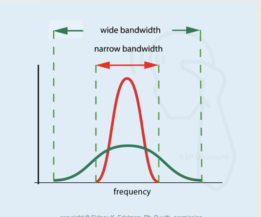
short duration events are
wide bandwidth

• Imaging probes (PW) broadband or wideband
• Short duration pulse
• Wide range of frequencies
• CW and therapeutic probes narrow bandwidth
• Long duration pulse
• One frequency
Bandwidth and pulse length are
inversely proportional
3. Low Quality Factor
unitless number that is INVERSELY related to bandwidth.
• a measure of the efficiency of the transducer in converting electrical energy to sound energy and vice versa.
Q-factor =
main frequency ÷ bandwidth
• Wide bandwidth probes have a low Q factor (sometimes imaging transducers are even called “low-Q”)
• Narrow bandwidth probes have a high Q factor
High/wider bandwidth probes
• Low Q factor
• shorter pulses
• more frequencies in the pulse
• Better image quality
• Example: Imaging probes (use damping material)
Low/narrow bandwidth probes
• High Q factor
• Longer pulses
• less frequencies in the pulse
• Example: CW and therapeutic probes (lack of damping material)
• Wide bandwidth
• Main Frequency 6MHz
• Bandwidth 3
Q factor = ?
6/3 =2
• Narrow bandwidth
• Main Frequency 6MHz
• Bandwidth 1
Q factor = ?
6/1 = 6
Sterilization
destruction of all microorganisms by way of extreme heat, chemicals, or radiation
instruments that penetrate the skin
disinfection
application of chemicals to reduce or eliminate organisms on an object (significantly reduces germs)
ultrasound transducers
both CW and PW transducer frequencies depend on the
SOURCE
Continuous Wave Transducers
Electrical Frequency= Acoustic Frequency
Pulsed Wave Transducers
characteristic of PZT determines the frequency
• Frequency determined by:
Speed of sound in the PZT element
Thickness of the PZT element
Why does the speed of sound in the PZT matter?
speed of sound is directly related to frequency
Speed of sound in PZT FAST= Higher Frequency
Speed of sound in PZT SLOW= Lower Frequency
Thickness of PZT affects Frequency
• PZT thickness and frequency are INVERSELY RELATED
• The thinner the PZT = the higher the frequency (shorter wavelengths)
• Typical thicknesses in diagnostic imaging are .2mm- 1mm
• Manufacturers make different thicknesses to create transducers of different frequencies
Thickness and fequency equation
= sounds speed in PZT/ 2 x thickness
