additive manufacturing
 Call Kai
 Learn
Learn Practice Test
 Spaced Repetition
 Match
Match Flashcards
 Knowt Play
1/23

There's no tags or description
Looks like no tags are added yet.
Name | Mastery | Learn | Test | Matching | Spaced | Call with Kai | Chat |
|---|
No analytics yet
Send a link to your students to track their progress
24 Terms
What is the difference between Subtractive, Formative and Additive
manufacturing. Give 3 examples of each process.
subtractive = remove material = milling, turning, Electric discharge machining (EDM)
formative = shape material = bending, moulding, casting
additive = add material = fused deposition modelling (FDM), stereolithography (SLA), selective laser sintering (SLS)


Wireframe, Surface and Solid Models are all valid CAD models, what is the
difference between them. Can CAD models be used directly in additive
manufacturing applications? why?
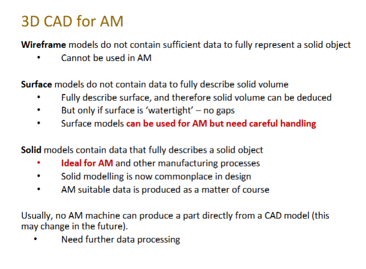
wireframe = geometry is described as a set of vertices and edges. Does not describe the surface or object’s interior
surface = geometry is described as a set of vertices, edges and faces. Does not describe object interior
solid = geometry described as a set of vertices, edges, faces and volumes, fully describes the object
CAD models are not used in AM applications = because it requires the geometry to be converted a sliced, layer-by-layer toolpath that tells the machine how to build the part.
What are the Advantages and Disadvantages of Additive Manufacturing?
Use freehand sketches to clarify your answer where possible

What are the 8 generic Additive Manufacturing process? List them in the
processing order and describe them showing why they are needed. Use
freehand sketches to clarify your answer where possible.
CAD model → Create the digital 3D component.
STL conversion → Convert CAD geometry into a triangulated surface mesh.
File repair → Check/fix holes, gaps and mesh errors.
Slicing → Divide the model into thin layers and generate toolpaths.
Machine setup → Prepare the machine, material and build platform.
Build → Manufacture the part layer-by-layer.
Post-processing → Remove supports, clean, cure, heat-treat or finish the part.
Inspection → Check dimensions, surface quality and whether requirements are met.


What are the limitations of STL files when used to represent a 3D object.
Are they representing Wireframe, Surface or Solid format? Use freehand
sketches to clarify your answer where possible
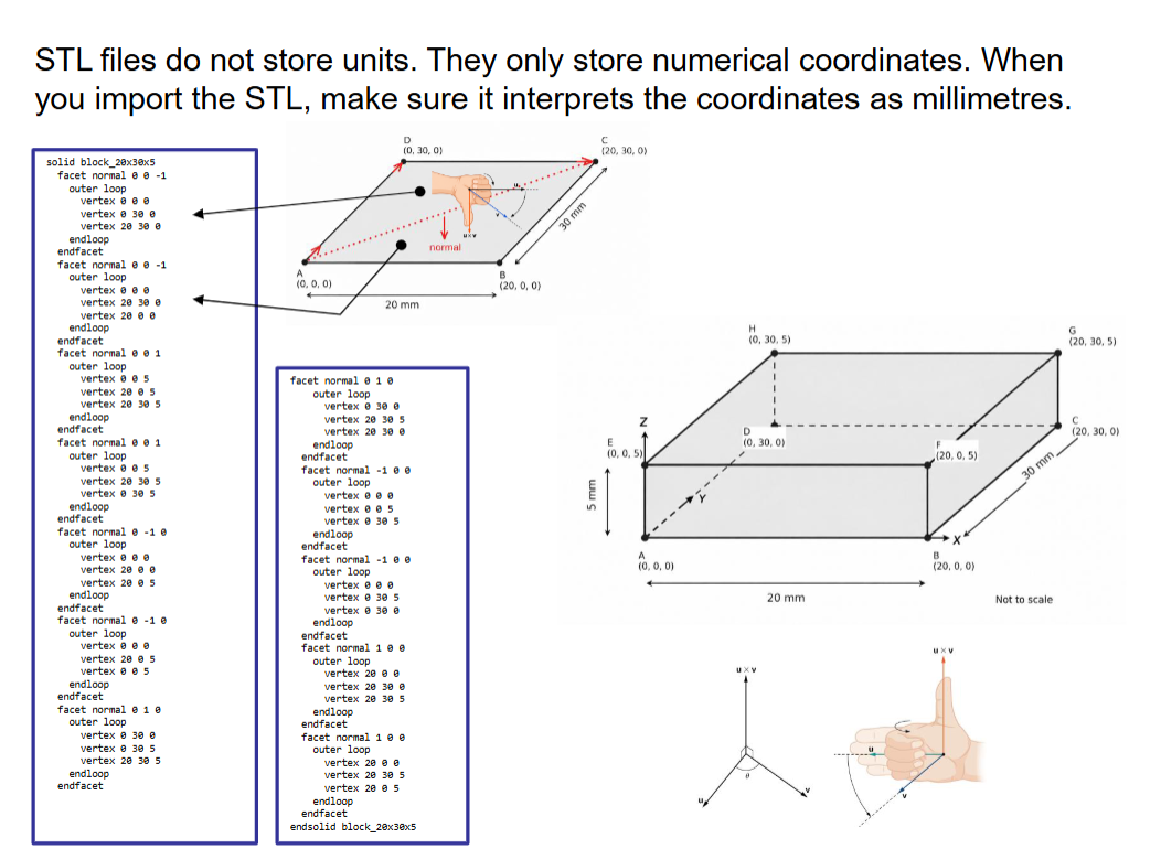
increasing the STL file resolution means that more triangles will be used approximating the surfaces of the 3D model will be better, but also increasing the size of the STL file, which may lead to a hanging problem while processing.
STIL file represents a surface


Is the layer-by-layer build style in FDM a limitation of the
technology? Why?

How does FDM print layer thickness affect the print surface
quality?
Smaller layer thickness: Produces a smoother surface with less visible layer lines and better detail, but increases printing time.
Larger layer thickness: Produces a rougher surface with more visible layer lines and less detail, but reduces printing time.
Exam key point: Layer thickness is a trade-off between surface quality and printing time.
Why are bridges, holes, and threads challenging in FDM 3D
printing? How do you deal with these challenges?
bridge = as the bridge gets longer the bottom layers droop and will not stick to the upper layers - deal with it by reducing the distance of the bridge or use support material
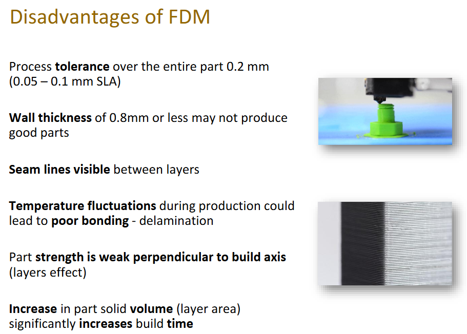
holes = horizontal holes are not perfectly rounded, while vertical holes come out smaller than intended, narrow holes are usually more distorted- deal with it by designing with a diameter bigger than 1mm or design with a small diameter and drill after

Elephant foot is a defect happening in FDM 3D printing.
Explain the problem and suggest a solution.


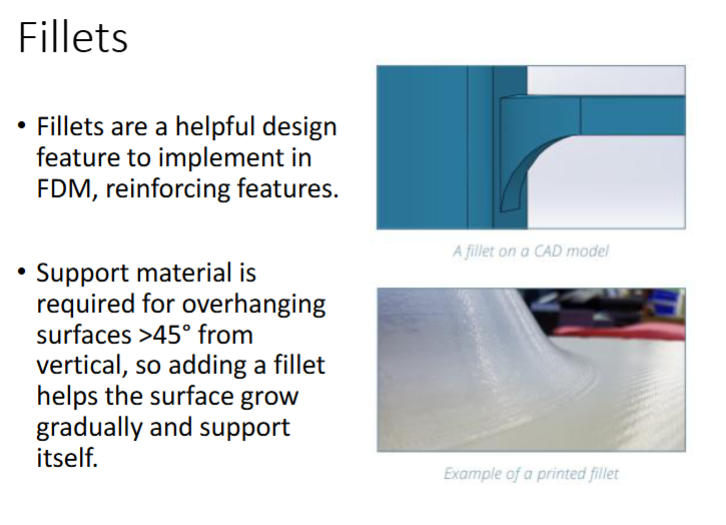
Do you agree that using fillets when designing 3D printed
parts corners is a must? And why?
Explain how 3D printing can optimise the geometry of
designed parts.
Complex geometries: Allows complex shapes that are difficult or impossible to manufacture using traditional methods.
Lightweight structures: Enables hollow parts, lattice structures and topology optimisation to reduce weight while maintaining strength.
Part consolidation: Combines multiple components into a single part, reducing assembly requirements.
Material efficiency: Uses material only where needed, reducing waste.
Exam key point: 3D printing enables design freedom, weight reduction, improved performance and reduced material waste.
explain why parts produced using Fused Deposition
Modelling (FDM) can exhibit anisotropic
mechanical behaviour. Discuss two design choices
that can improve their strength and printability.
Why FDM parts are anisotropic
Anisotropic behaviour means mechanical properties vary with direction.
FDM parts are weaker between layers due to poor interlayer bonding compared with the strength of the deposited filaments.
Therefore, strength depends on the print orientation and loading direction.
Two design choices to improve strength and printability
1. Print orientation: Orient the part so the main load acts along the deposited filaments rather than across layer interfaces. This improves strength. = for example a thread part designed for upright printing is easy to manufacture, but poorly orientated for tensile loading, by removing a section of the thread, the part can instead be printed flat on the build plate without supports, aligning the layers more favourably with the tensile load.
2. Part geometry and support: Design self-supporting features, such as chamfers instead of large overhangs, to reduce support material, printing time and defects. This improves printability. = Replace unsupported horizontal overhangs with self-supporting geometry, reducing support material, print time and post-processing


FDM basics

advantages of FDM

disadvantages of FDM
FDM vs SLA

STL code

Explain how Fused Deposition Modelling (FDM)
works, including how the filament is processed and
deposited to form successive layers
