4. Pipelines
 Call Kai
 Learn
Learn Practice Test
 Spaced Repetition
 Match
Match Flashcards
 Knowt Play
1/7

There's no tags or description
Looks like no tags are added yet.
Name | Mastery | Learn | Test | Matching | Spaced | Call with Kai | Chat |
|---|
No analytics yet
Send a link to your students to track their progress
8 Terms
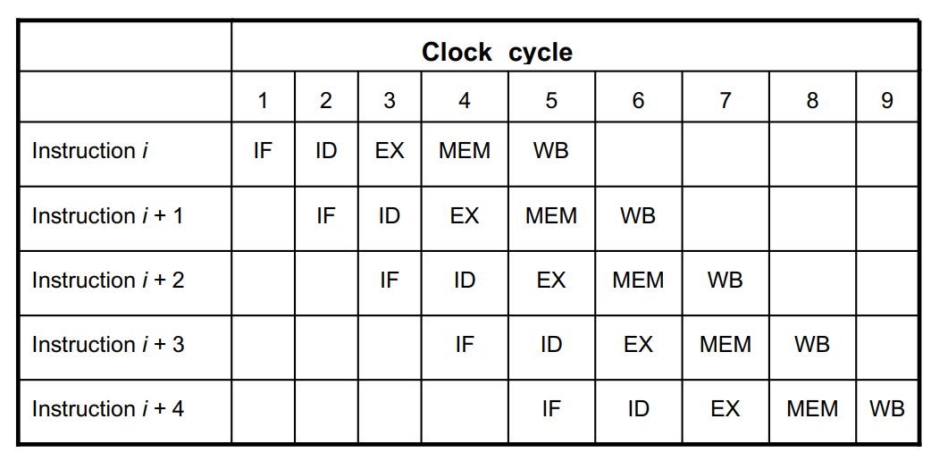
What are the 5 stages of an ideal processor pipeline?
The ideal 5-stage processor pipeline consists of:
Stage 1: Instruction Fetch (IF)
Stage 2: Instruction Decode (ID)
Stage 3: Execution (EX)
Stage 4: Memory Access (MEM)
Stage 5: Write Back (WB)
What occurs during Stage 1 — Instruction Fetch (IF)?
Stage 1 — Instruction Fetch (IF):
Fetches the next instruction.
Uses: PC (Program Counter) as instruction memory address.
Instructions are: 32-bit=4 bytes
PC increases by: 4 after each instruction fetch.
What occurs during Stage 2 — Instruction Decode (ID)?
Stage 2 — Instruction Decode (ID):
Instruction is decoded.
Registers are read.
What occurs during Stage 3 — Execution (EX)?
Stage 3 — Execution (EX):
ALU operations execute.
Load/store addresses are computed.
What occurs during Stage 4 — Memory Access (MEM)?
Stage 4 — Memory Access (MEM):
Accesses data memory.
Used for:
Load instructions
Store instructions
What occurs during Stage 5 — Write Back (WB)?
Stage 5 — Write Back (WB):
Results are written to registers.
Applies to:
ALU results
Load results
Note: Memory is not written in this stage.
What are the specific hardware components and timing rules associated with each pipeline stage?
Pipeline Component Stages:
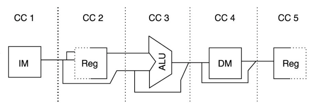
Stage 1: Instruction Memory (IM)
Instruction fetch
Stage 2: Register read and Instruction decode
Written in the first half of the cycle
Read in the second half
If a register is written and read in the same cycle, the read returns the new value
Stage 3: ALU execution
Stage 4: Data Memory (DM) access
Stage 5: Register write-back
What is the role of Pipeline Registers between stages?
Pipeline Registers:
Registers are added between stages.
At the end of each clock cycle:
Stage outputs are stored in registers.
Stored values become inputs for the next sta