ECSE 2170
 Call Kai
 Learn
Learn Practice Test
 Spaced Repetition
 Match
Match Flashcards
 Knowt Play
1/37

There's no tags or description
Looks like no tags are added yet.
Name | Mastery | Learn | Test | Matching | Spaced | Call with Kai | Chat |
|---|
No analytics yet
Send a link to your students to track their progress
38 Terms
Circuit Diagram Example
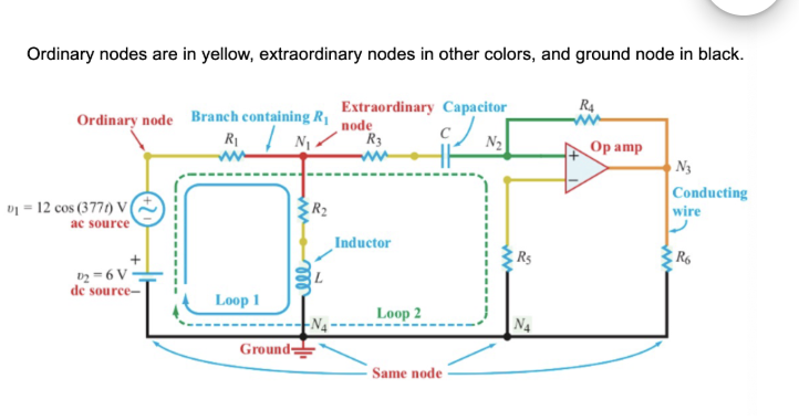
Node
Electrical conductor(s) or wires that connect two or more circuit elements.
Ordinary Node
An electrical connection point that connects only two elements.
Extraordinary Node
Node connected to three or more elements.
Ground Node
Node defined to be the zero-volts reference for the circuit.
Reference Node
Same as ground node (0 volts node)
Branch
The trace between two consecutive nodes containing one and only one element between them
Path
Any continuous sequence of branches, provided that no one node is encountered more than once
Loop
A closed path in which the start and end node are one and the same
Mesh
A loop that encloses no other loop
Planar Circuit
A circuit is planar if it is possible to draw it on a two-dimensional plane without having any two of its branches cross over or under one another (see figure below)
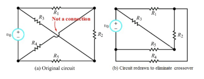
Non-Planar Circuit
If such a crossing is unavoidable, then the circuit is nonplanar

Series
Path in which elements share the same current. Series elements connect only at one end, never both ends. Rtotal = R1 + R2

Parallel
Path in which elements share the same voltage, which means they share the same pair of nodes (both ends) Rtotal = (1/R1 + 1/R2)^-1

Planar, R1 = 5 ohm and R2 = 6 ohm
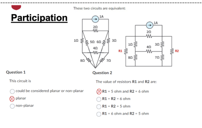
Five, Five

All nodes in this circuit are extraordinary, No two single elements in this circuit are connected in series

Charge
The basic quantity in an electric circuit and is time dependent.
Unit of charge = coulomb
e = 1.6 x 10^-19
Current
The rate of change of charge
Two most common types of current
Direct Current (DC)
Alternating Current (AC)

24 ohms
Left:
Right:
Parallel and Series

a) 3600 V
A) 3 Parallel
B) 2 Series and 1 Parallel
C) 2 Parallel and 1 Series
D) 3 Series

I2 = 450 mA, I0 = 0 A
Right Side:
KCL:
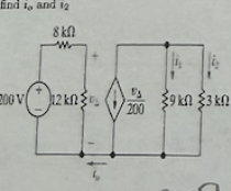
37.5 V
Left:
Right:
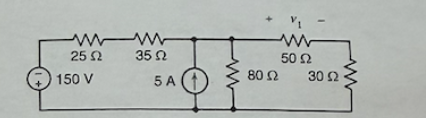
Ohm’s Law

Kirchhoff’s Voltage Law (KVL)

Kirchhoff’s Current Law (KCL)

I1 = 4mA, I3 = 3 mA

Supernode
Formed by a voltage source (dependent or independent) connected between two non-reference nodes.
Steps of Mesh Analysis
Identify mesh (loops)
Assign a current to each mesh
Apply KVL around each loop to get an equation in terms of loop currents.
Solve the resulting system of linear equations for the mesh/loop currents
Mesh 1: I1 = 9A
Mesh 2: 2(I2 - I1) + 4(I2 - I3) = 0
Mesh 3: 4(I3 - I2) + 8I3 + 40V = 0
Mesh 1:
Mesh 2:
Mesh 3:

Equ 1: I3 - I2 = 2
Mesh 1 (Equ 2): -24V + 12I1 + 8(I1 - I2) + 20(I1 - I3) = 0
Super Mesh (Equ 3): 10I2 + 20I3 - 20(I3 - I1) + 8(I2 - I1) = 0
Equ 1: I3 - I2 = 2
Mesh 1 (Equ 2):
Super Mesh (Equ 3):

a) 12 V, b) 7V, c) 0.25 A, d) -7 V

Vy = 7.517V, 207.167 mW = 207.167 mW (Pgenerated = Pabsorbed)
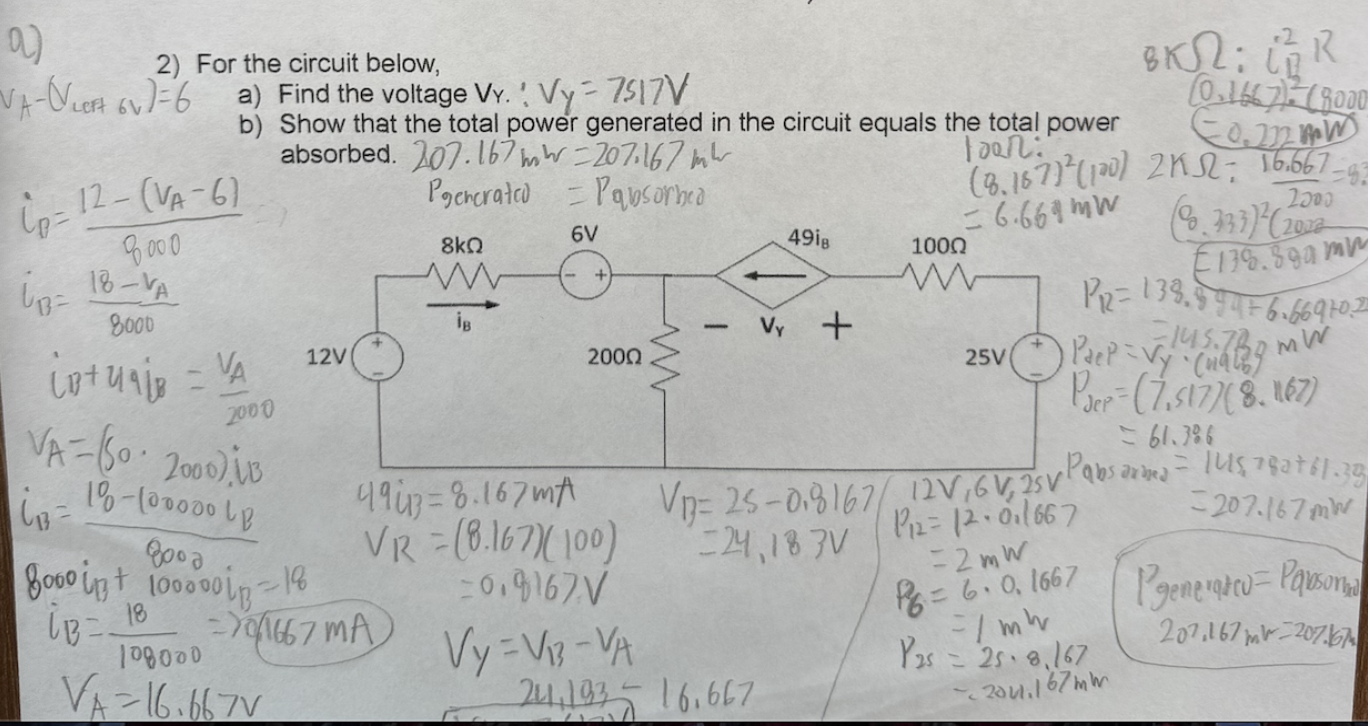
R1 = 200 ohms, R2 = 2k ohms

R1 = 1.875 k ohm, R2 = 3.75 k ohm, R3 = 7.5 k ohm, R4 = 15 k ohm

V = 18 V, 2A, -0.75
