Equipment/Oper Test 3
 Call Kai
 Learn
 Practice Test
 Spaced Repetition
 Match
 Flashcards
 Knowt Play
1/73

There's no tags or description
Looks like no tags are added yet.
74 Terms
Direct square law (exposure maintenance formula)
The direct square law maintains the mAs (technique) needed to maintain receptor exposure at varying SID’s.
The mAs varies directly with the square of the distance
Ex. If the distance is increased 2x, the mAs needs to be increased by an average of 4x
Ex. If the distance(SID) is decreased by HALF, mAs need to be decreased by about 4x
Direct square law used to be called exposure (film density) maintenance formula
Direct Square Law formula

Practice Question DSL = If 10mAs was used to produce a satisfactory image at 100cm distance, what new mAs would be required at a distance of 180cm?
32.4mAs
Direct Square Law Application
When doing a scoliosis exam, the scoliosis cassette requires 60-72 SID
When patient arrives, evaluate body habitus to determine technique or mAs would be used at 40 SID for a lumbar spine. (ex. 20mAs)
Simply multiply 20mAs x 4 = 80mAs
80 is our new mAs
Distance and mAs
Increasing distance from the source (getting farther away) = more mAs
Decreasing distance from source (getting closer) = less mAs
If your number doesn’t make sense, the formula was probably set up wrong.
Radiographic film
x-ray film must be processed to make visible radiography image that can be kept for years without deterioration; latent image (invisible) into manifest image (visible), required dark room + developing, rinsing, fixing, washing, drying
Film Disadvantages
intolerant to exposure errors; over saturated would look entirely black and under saturated entirely white without ability to post process; cannot duplicate without loss of quality; required lots of storage space
Computed Radiography CR
digital rad. introduced in 1981 by Fuji medical systems of Japan, the 1st commercial CR imaging system
slow to be accepted
installation increased in early 1990s
hospitals replaced film with CR systems (cassette based)
CR imaging plates (IP’s) retrofitted to existing room + read by CR reader (scanner) which can be shared between mult. rooms
CR aka PSP
Photostimulable Phosphor Plate CR (3)
cassettes are durable lightweight plastic material backed with thin sheet of aluminum that absorbs x-rays
has photostimulable phosphor (PSP) which is the chem. coating on phosphor plate in CR system
barcode label allows tech to label image w/ pt. info by id-ing barcode on exam request
CR basics (5)
IP used that has PSP
when x-rays hit phosphor, they create latent image (invisible image)
cassette then placed into reader + IP pulled into processor
RED LASER used to release stored photons
reader collects into + creates digital image to be displayed on screen
Digital Radiography (DR)
cassetteless system that uses digital plates that can be repeatedly exposed and does not need processor to develop radiograph image; conversion types 1) indirect vs 2) direct, both convert x-ray photons into a digital image
Dynamic Range
range of exposure that can be captured by detector, described the # of gray shades an imaging system can make, DR advantage bc it has wide dynamic range meaning IR responds to x-ray exposure + makes digital data over a wide range of exposures
Range of values that digital image receptor will respond
Greater dynamic range will yield greater contrast resolution
CR + DR Advances (6)
ability to post-process images in many ways to provide multiple views of the anatomy
in DR, brightness/contrast and image can be altered any time after completion of study without re-exposing the patient
digital images stored in the computer and can be transferred to mult. location on network/sent via email
no need for darkrooms/concern of exposing film exposure to light
removes need for chemicals to be used in film processing
images can be viewed in sec. vs. minutes
Exposure Indicator (7 manufactures)
numeric representation of receptor exposure, each manufacture has specific exposure indicator
Fujifilm = s value (S)
Carestream = exposure index (EI)
AGFA = log median of histogram (IgM)
Canon = reached exposure value (REX)
Knoica Minolia = sensitivity number (S)
Siemens = exposure index (EXI)
GE Healthcare = detector exposure index (DEI)
Fuji System = sensitivity # or S #
Fuji systems used with CR plates have indirect/inverse relationship with tech. factors
Ideal S number = 200
General acceptable range = 100-400
Low S# (below 100) = overexposed
High S# (above 500) = underexposed
S Number Scenario question: AP knee exposed using 8 mAs @ 60 kVp with S number of 44
not acceptable because overexposed and adjust by decreasing mAs (by half)
Sensitivity Number (S#) Fuji CR Equipment
s number indicator of photostimulable luminescence (PSL) give off the IP while being scanned by laser, on correctly positioned/processed image, S number indicate accurate exposure or over/under exposure
technique not only factor that affects the S number values, it can be affected by other factors during pt. exam such as;
scatter = more scatter - decreases image quality
distance = is SID accurate
collimation = good collimation reduces scatter
examination selected at reader = due to histogram analysis
Shimadzu - exposure index (EI) number
shimadzu uses exposure index (EI) number as an indicator which has a direct relationship with technical factors; general acceptable range is 100-400
high EI (over 500) = is overexposed
low EI (under 100) = is underexposed
Digital plate is canon plate = REX number (1000-4000)
DEI (deviation from exposure index)
a scaled representation of the difference of exposure index compared to the target index
deviation index card attached

Dose Creep
A pattern of radiation exposure levels (dose) being increased by clinicians over time in an attempt to achieve better image quality in diagnostic radiography.
Although unlikely to result in immediate harm, it's a problem that can have long-term consequences and that, over time, can affect many patients.
Possible disadvantage of digital imaging
Receptor Exposure
Amount of radiation striking the image receptor
Exposure the receptor to the right amount of radiation is the goal
Receptor exposure influencing factors (5)
mAs (primary)
kVp (15%)
Grids
Patient size
SID
Quantum Mottle (2)
Image noise that cause a grainy appearance due to underexposure
Not enough mAs used or not enough kVp
Saturation (2)
Severe over-exposure
Receptor was saturated with photons and lost soft tissue differentiation
X-ray photon pathways (3)
x-ray photon options when it interacts with matter
penetrates part + is transmitted to the IR
absorbed in anatomical part of photoelectric absorption
scattered by anatomical part through compton scattering
Scatter radiation + Compton Scatter
radiation that spreads out in different directions from a radiation beam when beam interacts with a substance like body tissue
compton scatter = photon enters atom in the body, partially absorbed by loosed bound outer shell electron resulting in electron being knocked out of orbit (ionization), electron is called a compton electron
Compton Scatter negative effects (3)
Patient dose: results in ionization, increases patient dose
Occupational dose: scatter can strike radiographer, 1# source of technologist
Image quality: decreases image contrast, more gray, high scatter results in image fog
Factors Influencing Scatter (4)
kVp: beam energy, increase kVp leads to increase amount of scatter, decreases image contrast, lower kVp produces less scatter
Field Size (FOV): light field size, decreases collimation leading to larger field size, more matter exposed leads to more scatter, smaller FOV leads to scatter
Patient thickness: more matter leads to more scatter, more matter in the way of the beam more compton scatter is created in thicker patients
Part density: more dense leads to more scatter, abdomen more dense than chest
kVp, Scatter and Contrast
kVp controls energy of the x-ray beam, also influences the amount of scatter that can happen when the x-ray photon interacts with the patient;
Higher kVp (increasing kVp) = higher energy, shorter wavelength, higher penetrating, higher amount of scatter radiation, decreased contrast (long scale, lots of gray scale, low contrast)
Lower kVp (decreasing kVp) = lower energy, longer wavelength, lower penetrating power, lower amount of scatter radiation, increased contrast (short scale, black and white and high contrast)
Beam Restrictors (3 types)
beam restrictors are devices that limit field size to a small area of interest
Aperture diaphragm: simplest type of beam restrictor and is made of lead/lead-lined metal sheet attached to the x-ray tube head
Cones and cylinders: mods of the aperture diaphragm, has an extended metal structure which produces a circular image
Variable-aperture collimator: most common beam-restricting device use in radiography, used for any field size
Positive beam limitation (PBL) (4)
light field limited to the size of the IR placed in the bucky tray
sensors in the bucky tray to sense size of the IR, does not mean bucky is lined up and does not mean you are detented will simply open light to the size of the IR
ex/ CR plates have certain sizes, when they are placed in the bucky tray the light will match the size/orientation of the IR; 8x10 IR light limited to the PSP plate; DR limited to the size of the DR plate 14x17 17x17
can turn key to open the light up but not recommended
Patient/Part Thickness (2)
x-ray scatter depends on thickness of anatomy that is being imaged using the x-ray, increased scatter leads to overall haze (more gray) in the background of the image
decreasing contrast: when patient body habitus larger photons have to travel more distance in the body and scatter events will happen more frequently
Radiographic grids (2)
grid is a device that reduces amount of scatter reaching IR and whose main goal is to INCREASE CONTRAST, placed on top of/in front of the IR
invented by Dr. Gustav Bucky in (American Radiologist) 1913
bucky trays always include a grid most are removable and some have secured grids that can’t be removed
Radiographic grid details
grids are made of lead strips alternation with interspace material
Interspace material options: carbon fiber, aluminum, plastic, NEVER LEAD
grids recommended for part 10 cm (4 in) or thicker
works as a filter = allows the primary beam to go through the interspace material and reach the IR
absorbs scatter radiation with the lead strips
disadvantage of grid use = increases pt dose since grid requires increased mAs
Types of Grids (2)
Moving grid or oscillating grid = table or wall bucky
grids move ~1-3 cm back and forth, must be fast enough not to see grid lines for short exposures
controlled by a strong magnet that releases the grid where springs bounce the grid back and forth
motion blurs out lead strip shadows by using vibration during the length of the exposure
moves during exposure
Stationary grid = table top/mobile or portable radiography (ports/ER)
doesn’t move during exposure
Grid Orientation (3)
Parallel (linear) grid: simplest type of grid + used commonly in diagnostic radiology all lead steps are running parallel
Linear grid: lengthwise - lines run long axis ||| ; crosswise - lines run on short axis =
Crossed grid: crosshatched pattern using 2 parallel grids (rare - seen in specials)
Focused grids (3)
slightly angled lead strips, has angled lines converge to a point in space called the convergence line
Focal distance = distance from convergent line to grid plane
Focal range = working distance range specified SID range per grid - 60-72 degrees
Angled lead strips (3)
both moving/stationary grids can have angled lead strips to match divergent beam
ex/ focused grid - angled lead strips to match the focus of the divergent x-ray beam
SID must be consistent with grid specifications (loon on the inside sticker for SID parameters of each grid)
Grid ratio (4)
relationship between the height of the lead strips and the distance between them
Grid ratio calculation/formula = H/D (height divided by distance)
Common grid ratios = 6:1, 8:1, 10:1, 12:1
higher the grid ratio = cleans up more scatter
Grid Ratio - Example Question: If the height of lead strips 1.6mm and distance between lead strips is 0.1mm the ratio of the grid is?
1.6 divided by 0.1 = 16:1
Grid frequency (3 Common ranges)
grid frequency is a measure of the number of grid lines (lead strips) per inch (or cm)
Common ranges:
40-50 lines/cm (100-120 lines/inch) for low frequency grids
50-60 lines/cm (120-150 lines/inch) for medium frequency grids
60-70+ lines/cm (150-170+ lines/inch) for high frequency grids
Grid ratio and efficiency
higher grid ratio = higher grid efficiency (bc more lead)
high the grid ratio = higher the mAs
more mAs = more radiation does to the pt
Processing errors (2)
Each setting selected on a control panel has an assigned histogram; a histogram is a graphical representation of expected exposure values or densities
Histogram for each body part is completely different so it is important to select correct setting on panel (run chest under chest, not finger)
Histogram analysis
Compares the radiograph you produced to the graph in the background
Value of interest (VOI)
Where your exposure values fall within the expected graph
Collimation
Correct collimation can affect you EI number and overall quality of your image
Increase field of view FOV (3)
larger light field
Increases scatter
Decreases image quality
Increase pt dose
Increase collimation (3)
make field smaller
Decreased scatter
Increased image quality
Decreased pt dose
Electronic cropping (masking) (3)
Electronically cropping out information after the exposure has been made and the image is processed (post processing)
ARRT is against post-exposure shuttering, cropping, electronic collimation, or electronic masking to eliminate any anatomical information
Proper collimation should happen at the time of exposure
IR errors (3)
1. Pixel malfunction = dead or damaged pixels appear as hyperdense artifacts
2. Receptor damage = Physical damage to the receptors causing hyperdense artifacts
3. Ghost images = caused by incomplete erasure of a CR receptor
Positioning errors (4)
Tube position = angle, direction
Part position = rotation, tilt, elongation, foreshortening, magnification
Receptor position = cassette or grid tilt
Collimation = symmetrical, watch field of view
Radiographic images must include (5)
Patient name
Patient DOB
Date of exam
Location of exam
Right or left marker
Errors (5)
Wrong patient
Wrong part
Wrong side
Wrong marker
Wrong annotation
Technique Chart (2 types)
A principal advantage of using technique charts is the consistency in exposure that occurs from one technologist to another and in comparison of examinations on the same patient on different dates and with different technologists.
Each chart provides the radiologic technologist with a guide to the selection of exposure factors for all patients and all examinations.
Types that require measurement of patient’s anatomy = 1) variable kVp chart, 2) fixed kVp chart
Variable kVp technique chart (3)
Uses a fixed mAs value and a kVp that varies according to the thickness of the anatomical part
For success, the radiologic technologist must be accurate in measuring the anatomical part before selecting exposure factors from the chart before selecting the exposure factors from the chart
Exposure directed by the variable kvp chart usually results in higher patient dose and less exposure latitude
Variable kVp chart (contrast scale) (2)
The basic characteristic of the variable kvp chart is an inherently short scale of contrast
In general, exposures made with this method provide radiographs of shorter contrast scale because of the use of lower kvp
Exposure latitude (5)
Exposure latitude is the extent to which radiographs can be overexposed or underexposed and still achieve an acceptable result
Ranges of exposure which produce quality images
Digital imaging has a wide exposure latitude latitude for a range of technical factors (kvp and mAs values that will still produce an acceptable radiograph
Advantages to exposure latitude = less repeats
Disadvantages = dose creep with over exposure to patient
Fixed kVp technique chart (5)
The fixed-kvp radiographic technique
Developed by Arthur Fuchs, it is a method of selecting exposures that produce radiographs with a longer scale of contrast
The kvp is selected as the optimum required for penetration of the anatomical part.
This usually results in somewhat higher kvp values for most examinations than are produced by the variable-kvp technique.
The benefit of this chart is a lower patient dose
Fixed kVp chart continued (5)
Kvp is fixed and does not vary accordingly to different thicknesses of the anatomical part
The mAs value is changed according to the thickness of the anatomical chart
Specific measurement of the part is not critical because part size is grouped as small, medium, or large.
Fixed kvp charts also can be calculated with specific mAs values for every 2cm thickness
This approach is more accurate than is use of subjective small, medium, and large labels
High kVp technique chart (5)
The kvp selected for high-kvp technique charts is usually greater than 100
For example, overhead radiographs for procedures in which barium contrast medium is used would use 110-120 kvp for each exposure
High kvp exposure techniques techniques are ideal for barium work to ensure adequate penetration of the barium (56 atomic number)
Chest radiography is another example. Most chest kvp settings are at 117 kvp
High kvp = long scale contrast (low contrast)
Grid factors
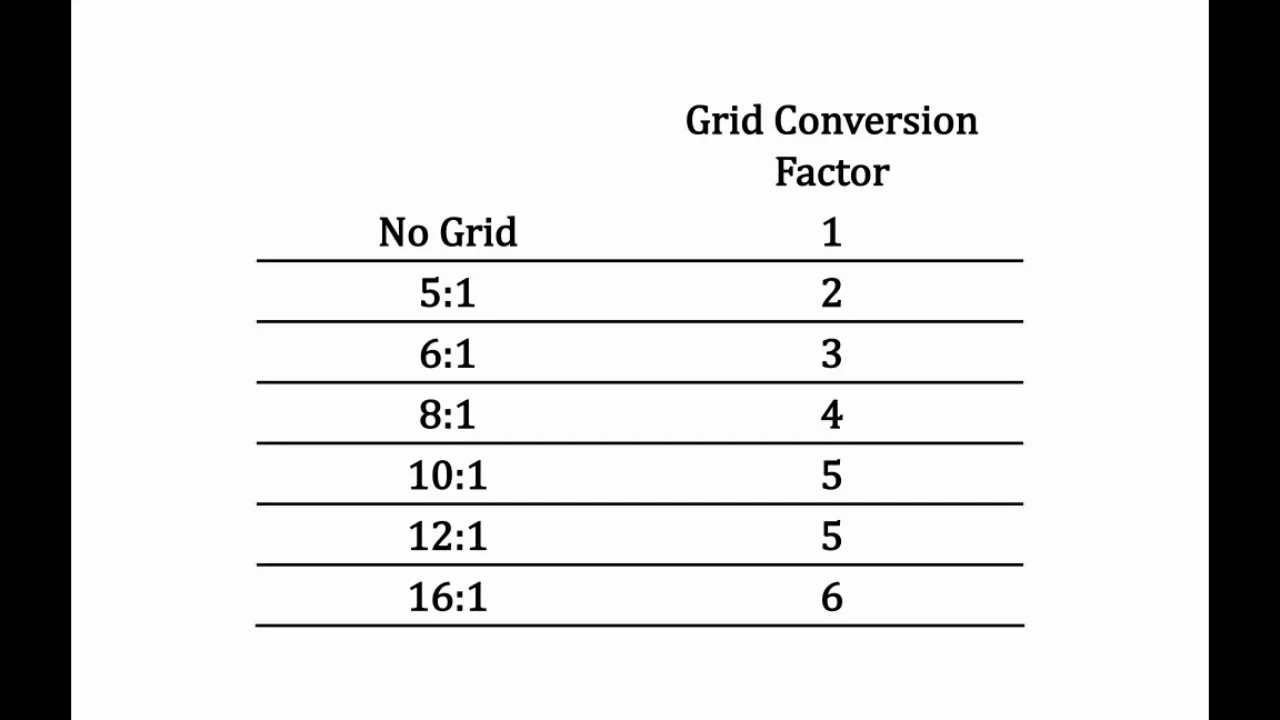
Grid conversion formula
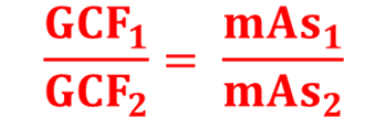
Practice question grid conversion: 4 mAs nongrid was used on original exposure. Repeat exposure was made using 10:1 grid. What is the new mAs? (simply multiply the the original mAs by the grid bucky factor)
a 10:1 has a bucky factor of 5
Multiply 4 x 5 = 20
New mAs using a grid will be 20mAs
Grid cut off
An unwanted absorption of primary x-rays (useful beam). We want the primary beam to pass through the grid to the IR. ideally only the scatter radiation is absorbed.
The most common error in the use of grids is improper positioning
If there is a positioning error with either the tube or the grid, the lead stripes will not be aligned with the divergent beam correctly (most often seen with parallel grids)
Grid errors (6)
angulation error
Off-level error
Off-focus error
Off-center error
Upside down grid error
Moire pattern
Angulation error
Occurs when the tube and beam are projected against the angulation of the lead stripes
Overall lowering of receptor exposure over the entire radiograph
Tube angulation used on a flat grid
Appears as underexpsed with grid lines present.
Off-level grid error
Occurs with a straight beam but a tilted grid
Overall decrease in receptor exposure (underexposed image)
Similar to angulation error
Appears as an underexposed image
Off-focus error
An incorrect SiD is used with a focused grid
Focused grids have a specified SID
Images will present with having a large decrease in density across the edge
Appears as grid cutoff will be toward the edges of the image
Off-center error (lateral decentering)
Occurs when the central ray of the beam is off center of a focused grid
Uniform loss of receptor exposure across the entire image
Appears as grid cutoff across entire image
Upside down grid error
Occurs when a focused grid is placed upside down on the image receptor
If grid is palace upside down, appears as severe grid cutoff on both sides of the image
Moire pattern
A grid error with computed radiography (CR) cassettes
A wavy artifact caused by grid lines running parallel to the laser scanning motion
Air gap technique (3)
Alternative method of reducing scatter radiation reaching the image receptor; can be used in place of a grid if one is not available
Image receptor is placed 10-15 cms from the patient causing a large portion of scattered x-rays to not interact with the IR
Technique is similar to using an 8:1 grid
Virtual grid
Digital scatter correction reduces the effect of scatter radiation for non-grid bedside examinations
Scatter correction reduces the effect of scattered radiation for non-grid bedside examinations
Scatter correct software mimics the result of using a grid. Where a grid physically reduces scatter and thereby increases the image contrast, the software does this virtually.
30% weight reduction for technologists
How does using a grid increase pt dose ?
A grid is commonly used on larger anatomical parts
When a grid is applied mAs is increased by a factor of 3, 4, or 5 most commonly.
mAs controls the number of x-ray photons (beam quantity)
When we increase mAs, we increase patient dose
Exams on pediatric patients, that are smaller in size, should be done non grid if possible