Muscle and Peripheral Nerve Interfacing
 Call Kai
 Learn
Learn Practice Test
 Spaced Repetition
 Match
Match Flashcards
 Knowt Play
1/53

There's no tags or description
Looks like no tags are added yet.
Name | Mastery | Learn | Test | Matching | Spaced | Call with Kai | Chat |
|---|
No analytics yet
Send a link to your students to track their progress
54 Terms
Targeted nerve reinervation
e.g. rewiring nerves from residual limb to pectoral muscle to amplify nerve signal to use to control bioprosthesis. Also retraining lat skeletal muscle into cardiac muscle for cardiomyoplasty for congestive heart failure

Nerve cuff
wraps around nerve with multiple sensors to detect activity

Nerve cross section
not round and have distinct fascicles that have different targets

FINE electrode
flat interface neural electrode, multiple contacts across nerve, treats nerve as more flat

Slant array
has needles of different lengths that go into the nerve
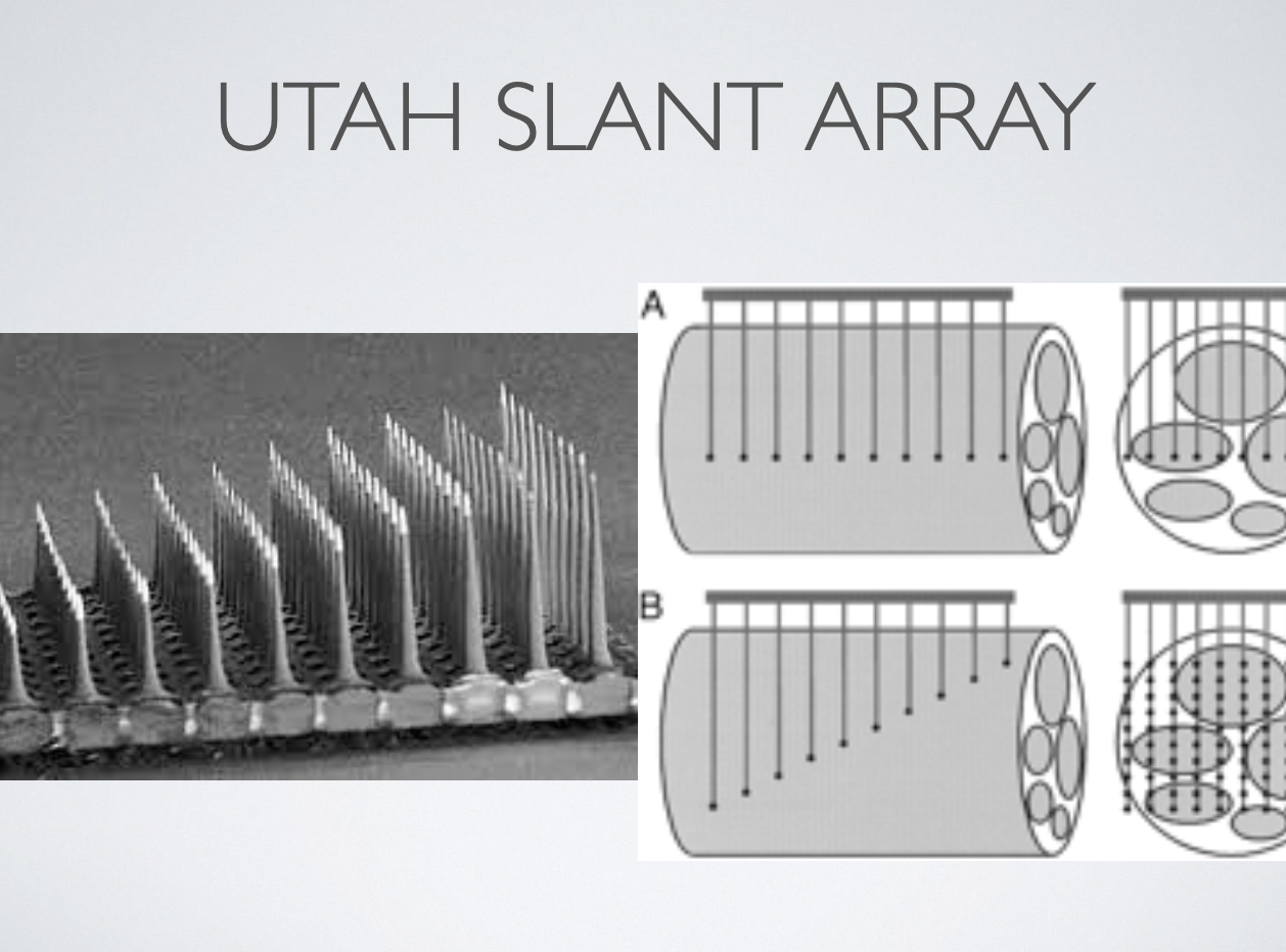
Peripheral nerve electrodes
Can use cuff, LIFE, or TIME electrodes

Regenerative sieve electrode
Cut the nerve and take advantage of regenerative properties. Have nerve grow through a sieve with electrodes. Balance between sieve size, if too small then nerve won’t properly regenerate.

Monopolar stimulation
Creates a wide, radial, and homogenous electrical field around a particular electrode. Modeled in regenerative sieve electrode, when activated induces activity in the surrounding area.

Current Steering - multipolar stimulation
regulate current across all electrodes to target specific area. So can block activation at non-target muscles and focus on particular target tissue

Micro-channel sieve recording
Provides tunnel to amplify nerve signal. Significantly increases detectable voltage from nerves to quantify neural drive and approximate firing rate and activityT
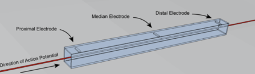
Tripolar microchannel
to be able to direct current through microchannel, determined to need two current sources and a current sink in the middle, otherwise current would go all the way around to the other current sink. Had to provide one way flow for current. Reduced the stimulation current needed for 50% of activation of fibers in channel. Minimizes stim artifact.

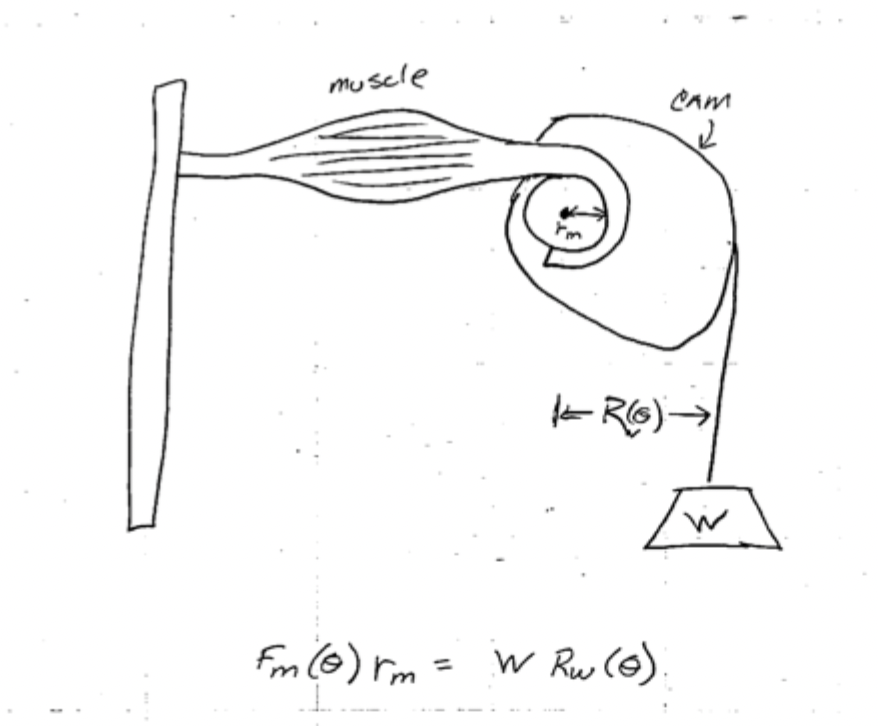
Design using force-length relationship
like for gym bicep curl machines, device cam shape so that maximum force is exerted on the muscle during peak force-length. For active force, experience peak force at resting length, for passive, force increases with length.
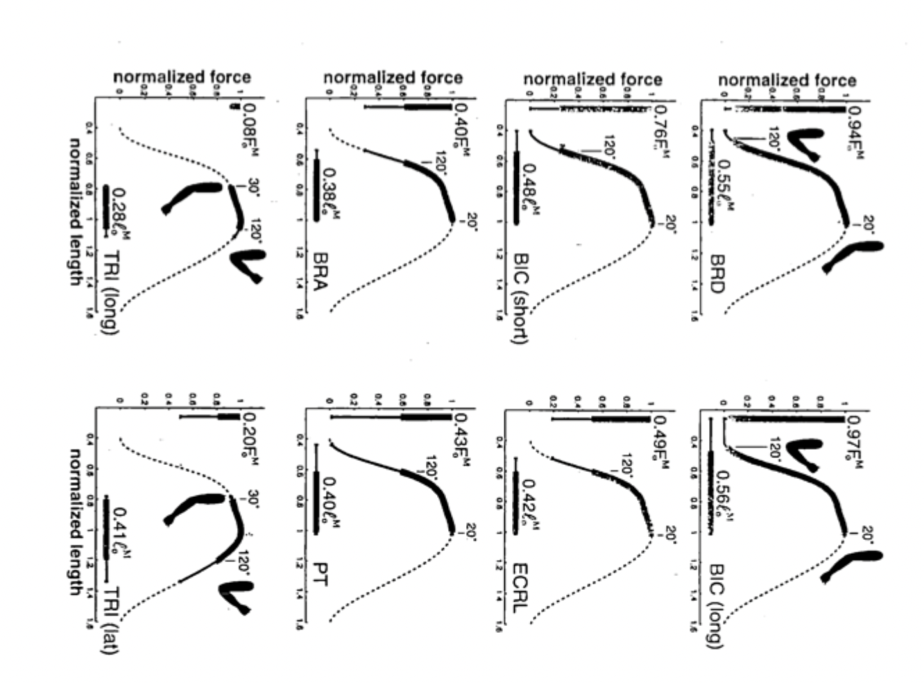
Muscle force-length relationship
For active force, experience peak force at a given length/angle. For passive, increases with increasing length/deformation. .

Muscle Maximum force-length
Different muscles experience different locations/angle of peak force and is generally where that muscle operates. Happens when cross-bridge overlap is maximal
Muscle Force-velocity relationship
As velocity increases (first deriv w.r.t. time of length), then force decreases. E.g. the faster you go, the weaker you are. Therefore peak muscle force during isometric contractions

Muscle peak power
Occurs typically during peak force-length where over the course of a muscle movement, the deformation or angle change happens the fastest

Muscle movement inertia
Need to look at acceleration profile of muscle contraction. Reaches a peak then goes to zero before going in other direction and returning to zero. Time to increase acceleration due to inertia. So if building a cam device, can reduce the radius of the cam when acceleration is at its maximum and then take advantage of momentum when decreasing speed to reduce the radius since less continued force is required to maintain motion.

Sir Isaac Newton
1687, traditional laws of physics and motion, F=mA governs
Thomas Kane
Studied how cats land on their feet, 1955 worked at Stanford, solving equations using matrices and simplifying more complicated models.

Kane Equation
mQ(dot dot) = T + V + G + E
m = mass matrix, T = torques, V = inertia, G = gravity, and E = external.
Q(dot dot) is the angular acceleration of angles in a mdoel
Planar degrees of freedom
3: x, y, rotation
Loss of DOF with pin
Lose 2 DOF for each pin, lose 1 for a rolling pin
4 bar linkage
only 1 DOF

bicycle model
Only 2 DOF. Think of upper leg, lower leg, and foot as 9 total DOF. 3 pins holding leg together = -6 DOF and then another ‘pin’ of the pedal = - 2 DOF. So that’s 1 DOF. Then the pedal itself has 3 DOF but it has a pin so becomes +1 DOF. So in total 2 DOF: pedal angle and then angle q3.

torque vs moment
Torque is a dynamic turning force that causes an object to rotation or change its angular acceleration. Can think of as moments of a couple, e.g. there is no reaction force, there is just an equal but opposite moment on opposite sides of the center of rotation that cause active rotation.
Moment is a general or static tendency of a force to make a body bend, twist, or rotation around a pivot, often occurring in stationary or balanced structures (resisted by reaction forces).
E.g. in mechanics of solids, we were interested in moments on a beam, but in physics and considering angular motion, think about torques that inact physical motion.
Moments
moment = cross product of radius and force.
Radius is defined from P to any point on the line of action. So can think about the component of r that is perpendicular to the force is what defined the moment.
Must be defined by a force AND a point of reference

Torque
Moment of a couple and does not need a point of reference. Couple is 2 forces of equal and opposite magnitude and has zero net resultant
Does not need a point of reference. So regardless of where you put your center point.

Muscle Reaction Force
A muscle needs a rxn force at the joint to make a couple to force a reaction (torque). So couple of contractile force of muscle and then rxn force of join.

Knee joint movements
A combination of slipping and rolling. Want to avoid sliding.

ICR
Instantaneous center of rotation
Slipping
The wheel rotates about its same center. There is a rightward force on top and leftward force on bottom, so no overall movement of wheel. Vc = 0. ICR is the axis of the wheel

Sliding
The center, top, and bottom of the wheel are all moving in the same direction with the same velocity. Vc ≠ 0. Ligaments generally prevent this type of movement in the knee

Rolling
The bottom has no velocity but the top does and the middle has half of the velocity of the upper part. So can think of as a falling log. The ICR is the bottom of the wheel or point of contact with ground. Vc = ½ Vp

Finding the ICR
Assumes rotation only (no translation). It is the point that has zero velocity in both reference frames if thinking of a two component pin-jointed framework.
Can use method of reuleaux and tangent method
Method of Reuleaux
Method to find the ICR. Look at reference frame of limb at point A of movement and at point B of a rotational movement. Draw lines connecting points at the top and bottom of the limb between points A and B. Draw a perpendicular line between the two lines and where they intersect is the ICR

Tangent Method
Method of finding the ICR. Looks at the tangent lines of the instantenous velocity of two points along a limb. Where the lines intersect is the ICR. More accurate method.

Knee braces
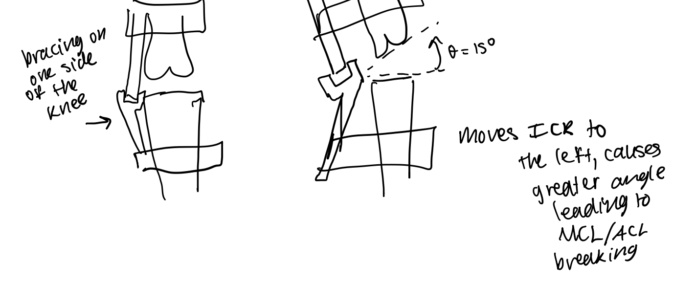
If one sided support, extends the ICR to the left of the knee. If receiving impact force from other direction, can cause more severe injury leading to MCL/ACL breaking. If force leads to same angular displacement with and without brace, if ICR is to the left, will cause significantly more vertical displacement in knee than if ICR is at the center of the knee. Need to provide bracing on both sides in order to maintain central ICR.
Hip joint
Functions as a secure ball and socket model that is very stable. Tightly enclosed.
Shoulder Joint
Less stable than ball and socket, relies on rotator cuff of 4 muscles to hold in place as opposed to tendons and ligaments.
Golf ball and T model
Very small surface area to allow for range of motion
Can think of muscles as ‘dynamic ligaments’ that allow for greater ROM
Rigid Bodies and reference frames
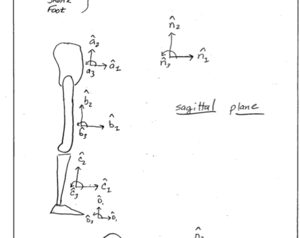
Modeling the lower body as 4 rigid bodies representing the pelvis, the thigh, the shank (calf), and the foot. Each rigid body has its own reference frame indicating up/down, left right, and in out relative to the rigid body.
Sagittal plane
looking at the side view

Rotation Matrices
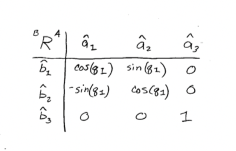
Provide angular relationships between bases. Allow for the conversion of the reference frame of one rigid body into another.

Rotation Matrix example
b1 = cos(q1)a1 + sin(q1) a2 + 0
b2 = -sin(q1)a1 + cos(q1)a2 + 0
b3 = a3
When assembling matrix, remember that letter on right represents what to put into the top column of the matrix in the table of direction cosines.
Indirect rotation matrix
Can use matrix multiplication to get rotation about one join with reference to another indirectly. E.g. aRc =( aRb) (bRC_, cancel out the inner terms

3D motion
Need to break down a 3D motion into x, y, and z changes and consider changes to the reference frame in each direction separately. E.g. from A to A’, then A’ to A’’, hen A” to A’’’. Order matters, we are using x, y, and z order.
So first, look at add/abduction
Then look at y rotation.
Then need to look at individual rotation matrices across each individual movement and convert into matrix multiplication to get to the desired rotation matrix vector.

Transformation of coordinates
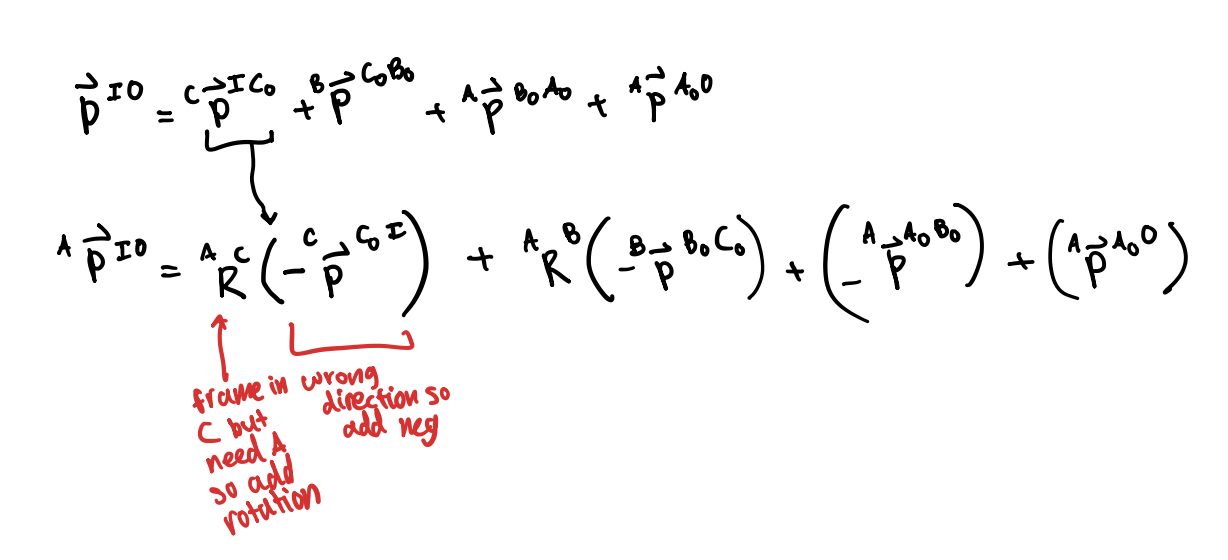
Vector summing. So need to look at the radius/position vector from point A to B, then B to C, and can sum together to get the overall position vector between A and C.
But when looking at the position vectors, these might need to be converted into a particular reference frame. E.g. A. So in that cause, you would need to include matrix multiplication with the rotation matrices to convert into the desired coordinate system
Purpose of rotation matrices
Help you convert vectors from being in terms of one reference frame, to being in terms of another.
Angular velocity
Defined by the rate of change of the angle between two reference frames.
Use symbol w to represent.

Law of addition
For angular velocities, when converting between frames, instead of using matrix multiplication to cancel out, you sum them together. E.g. aWb = aWa’ + a’Wa’’ + a’’Wb

States of a biomechanical system
Position and velocity, or angle and angular acceleration.
Angular acceleration concepts
Angular acceleration is the time based derivative of the angular velocity w which can be broken down into components in x, y, and z. But, we can instead look at the velocity of a given point in reference to a given point and look at the second derivative of that position to determine acceleration by using omega

Finding angular acceleration method
Can use any vector P fixed in any reference frame to find angular acceleration by using the angular velocity to convert.
Can use cross product of angular velocity and position vector to get first derivative of position vector with respect to time. Take cross product again to get second time derivative. This involves taking derivative w.r.t. of the angular velocity, which is angular acceleration, so using that equation can solve for an equation with angular acceleration.

Velocity Vectors
Usually the linear velocity of one or two points is known, but you may need to convert it into the target reference frame. To do so, need to use the cross product of the rotational velocity and position vector (gives you the first derivative of the position vector w.r.t. time and so the slope)

Coriolis Forces
If something is moving relative to a rigid body that is also moving in reference to a given point, then coriolis acceleration describe part of how the moving item moves relative to the reference point, which is affected by the acceleration of the object.
It shows up in an acceleration term.
Rule of coexistence: if either the angular velocity (w) or the relative linear velocity (v) is zero, there is no Coriolis force or acceleration.