11.1 Theory of Flight
 Call Kai
 Learn
 Practice Test
 Spaced Repetition
 Match
 Flashcards
 Knowt Play
1/49

There's no tags or description
Looks like no tags are added yet.
50 Terms
Axes and Motion
Lateral Axis (Pitch) - oriented horizontally and runs from wing-tip to wing-tip.
Longitudinal Axis (Roll) - runs from the nose to the tail of the aircraft.
Vertical Axis (Yaw) - oriented vertically and runs through the centre of gravity of the aircraft.

Primary Flight Controls
Control the A/C
Ailerons
Elevators
Rudder
Secondary Flight Controls
Enhance A/C flight Performance
Ailerons
In a Left turn, the Left aileron goes UP and the right aileron one DOWN
Dynamic Energy
Energy in the air is proportional to the square of the airspeed - if the airspeed is doubled, the pressure felt on the control surface is quadrupled.
In order to combat this, some larger aircraft are equipped with inboard and outboard ailerons. During take-off, landing, and low speeds, both sets of ailerons deflect in response to a roll command giving maximum leverage.
As aircraft speeds increase, the outboard (low-speed) aileron is locked out. Roll control is then exercised through the use of roll spoilers and the inboard (high-speed) ailerons which are smaller and positioned in a more rigid section of the wing

Spoilers
Roll or flight spoilers are used to supplement aileron control by reducing lift on the wing with the up-going aileron. This action also counteracts the effect of lift-induced drag that causes adverse yaw.
Roll spoilers help to execute an accurate turn and reduce the requirement for a large aileron deflection at high aircraft speeds.

Elevators
Located on the trailing edge of the horizontal stabiliser
Affect longitudinal or pitch control around the lateral axis.
Furthest away from the aircraft’s centre of gravity to exert greater leverage.

Stabilators (ALSO KNOWN AS - “all-moving tail or slab tail”)
combine the action of an elevator and a horizontal stabiliser
normally equipped with an anti-balance tab.

Variable Incidence Stabilisers (THS)
is a stabiliser that has a limited range of movement and is used only for pitch trimming.
When the angle of attack of the THS is increased, the effect is a nose-down attitude
has the advantage of reducing drag due to the reduced requirement for elevator deflection.
controlled via a screw jack mechanism and operated from the flight deck with pitch trim wheels which have an instinctive movement

Canard (Forward Wing)
horizontal surface that is located forward of the main wing to provide longitudinal stability and control.
Provide pitch control, which involves the rotation of the aircraft around its lateral axis.
Their forward position can improve the aircraft's natural stability by providing a nose-down force.
Helps Stall Prevention by stalling first causing nose down that helps recover.

Rudder
Provides control of the aircraft around the vertical axis.
The Rudder is only used independently to correct the direction of the aircraft in crosswind conditions or in the event of single-engine failure.
Rudder Limiters
the rudder limiting system restricts the rudder's amount of deflection with increasing airspeed
Excessive use of the rudder at high speeds can exceed the ultimate load of the vertical stabiliser, causing structural failure.
Adverse yaw
the down-going aileron increases lift, which then increases lift-induced drag on the related wing.
can be countered by - Frise Ailerons and Differential Ailerons

Adverse roll
Aircraft with a high vertical stabiliser can be affected by adverse roll
As the centre of pressure is high above the longitudinal axis, the result is a rolling moment in the opposite direction to rudder deflection.
An aileron-rudder interconnect system helps to overcome adverse roll.
Yaw and Roll
Swept wing aircraft are particularly prone to instability in yaw and roll and can sometimes oscillate around both axes as a product of the yaw/roll relationship.
This oscillation is known as Dutch roll and can be problematic for both the aircraft and the crew.
Oscillations of the rudder are sensed and corrected by the use of a yaw damping system.
This system sends a signal to the power control unit to ‘steady’ the uncommanded rudder oscillations.
The yaw damper is a servo that moves the rudder in response to inputs from a gyroscope or accelerometer that detects the yaw rate.
A series of accelerometers or rate sensors (gyros) in the tail of the aircraft constantly communicate yaw trends with the rudder servo system to provide adequate damping information.
Elevons
control surfaces for Pitch and Roll are combined and located at the trailing edge of the wing.
When a pitch input is commanded = Deflect up and down collectively
When a roll input is commanded = Move in opposing directions
When pitch and roll combined input = move differentially in the same direction

Ruddervators
check notes too page 6 if pic confused

Slots
Slots allow high-pressure air from beneath the wing to accelerate through to the top of the wing and re-energise the boundary layer to prevent separation, stagnation, and stall at higher angles of attack.
Slots themselves do not increase lift, they re-energise the boundary layer to delay separation and prevent stall
Slats
SAME AS SLOTS HOWEVER - The difference is that slats are movable and are retracted forming the leading edge when not needed.
they produce a convergent slot and increase the camber of the wing. The increase in camber causes an increase in the overall lift.
Plain Flap
increases the lift by around 50 - 55%.
Split Flap
increases the lift by around 60 - 65%.
Slotted Flaps
can be designed to be single-slotted, double-slotted, or even triple-slotted.
increases the lift by around 65 - 70%.
Fowler Flap
The Fowler flap increases the lift by more than the other types of lift devices, up to 95%
Leading Edge Droop
entire leading edge section rotates downwards, whereas a slat is a panel that moves away from a wing’s leading edge when it is deployed.


Krueger flaps
hinged at their foremost position that, once deployed, actually become their trailing edges, hinge forwards from the under the surface of the wing, increasing the wing camber and the maximum coefficient of lift.

Flaperons
is an aileron that can also function as a flap which “droop”; They can still move up and down differentially while drooped to provide an aileron control.
Deflect collectively = to act as flaps
Deflect differentially = to act as ailerons

Spoilers - (PIC REFERS TO ROLL SPOILERS ONLY)
Flight spoilers (Speed brakes) - while airborne is normally limited to an angle which is less than the deflection achieved in the ground spoiler mode. / Wing spoilers must not be deployed during the final phase of the approach to landing. The induced loss of lift results in a higher-than-normal stall speed and can result in a hard landing. / also talks about position of them when armed etc
Ground spoilers (Lift dumpers) - conditions of it = common sense = airspeed wheels etc
Roll spoilers - used in conjunction with ailerons to enhance roll control (prevent adverse yaw) / often outboard or mid-span spoilers, while descent control spoilers are inboard spoilers. / Spoilers allow the aircraft to roll without creating the twisting force at high speed.
speed brakes - As with spoilers, they permit a controlled descent without an increase in speed and assist in slowing the aircraft down on landing. / can be used during the final approach to touchdown as well as after landing.

Wing Fences (“boundary layer fences” or "stall fences".)
Reduce the effects of the spanwise flow and help reduce the wing tips stalling on swept-wing aircraft.
Wing fences are Flat plates fixed to the upper surface or wrap around the leading edge.
They are installed at a position on the leading edge where it will limit boundary layer outflow before it begins to stagnate.
They delay the onset of boundary layer separation and stall at the wing tip.

Saw Tooth Leading Edge
Boundary Layer Control - EDIT OR HIGH
The spanwise flow has the effect of making the wing tip prone to stall if the angle of attack is increased.
If both wingtips stall at the same time, the Centre of Pressure (CP) moves forward closer to the Centre of Gravity (CG). If the CP moved forward of the CG, it would cause a significant nose-up pitch moment which would worsen a stall situation.
The design solutions to the effect of this spanwise flow are to limit the travel of that boundary layer spanwise flow or to re-energise that slow-moving boundary layer area.
Vortex Generators
Takes high-energy air from outside the boundary layer and mixes it with low-energy air to re-energise the boundary layer.
They are often installed in opposing pairs so that the vortices mix. They are presented at a high Angle of Attack (AOA) to the airflow to create a strong vortex.
Stall Wedges (also known as STALL STRIPS)
At high angles of attack, the strip encourages the airflow at the leading edge to separate, initiating a flow separation earlier than at other positions along the wing.
positioned on the inboard section of the wing, which encourages the root to stall first.
Turbulence from the wing root will also buffet the tail giving the pilot some physical warning of an impending stall.
Leading Edge Devices
These devices feature a convergent duct that accelerates the airflow from the high-pressure area underneath the wing to reinvigorate the airflow on the upper surface.
Boundary layer suction is a control technique using a pump system. This method consists of operating a powered system to suck the boundary layer flow from closely spaced vertical slots.
Trim Tabs (Secondary Flight Controls)
Trim tabs are small control surfaces located on the trailing edge of a primary flight control surface and can be fixed or moveable. (fixed = adjusted on ground)
The trim tab is deflected in the direction that opposes that of the flight control surface deflection.
For example, if the aircraft is flying left wing low, the lift on the left wing needs to be increased and the right wing needs to be decreased. - EXAM EXAMPLE (SAMPLE)

Balance Tab
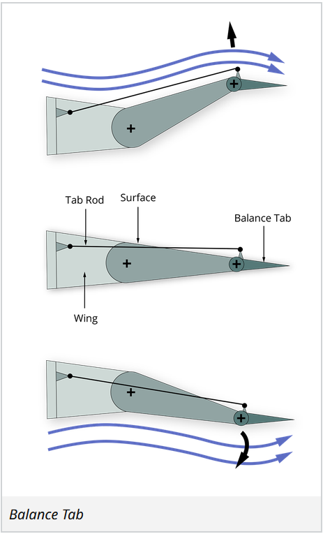
Balance tab fitted at its trailing edge / Reduces efficiency of the control surface
A balance tab is connected to the control surface by a fixed rod so that when the control surface is deflected, the tab automatically moves in the opposite direction.
The balance tab changes the camber of the control surface, and the accelerated air produces a low static pressure area at the trailing edge.
Anti Balance Tab
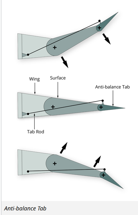
same as Balance Tab except - moves in the same direction as the control surface giving resistance to the movement.
Disadvantage is more effort is needed
deflection of the anti-balance tab is greater than the deflection of the control surface.
used where the input of control may be too sensitive,
Servo Tabs (Controlled by pilot)
Servo tab moves in the opposite direction to the flight control.
Free to move at its hinge point, and the pilot feels the air load on the tab and not on the control surface.


Spring Tabs
works like a servo tab and only works when the force on a flight control surface reaches a certain value
Incorporated into the input linkage is a spring mechanism that must be overcome when the actual main control surface loading becomes too high for the pilot to move.
The tab moves in the opposite direction to the control surface
check first pic example

Mass Balance
The Centre of Gravity (CG) of a control surface must act as close to the hinge line as possible.
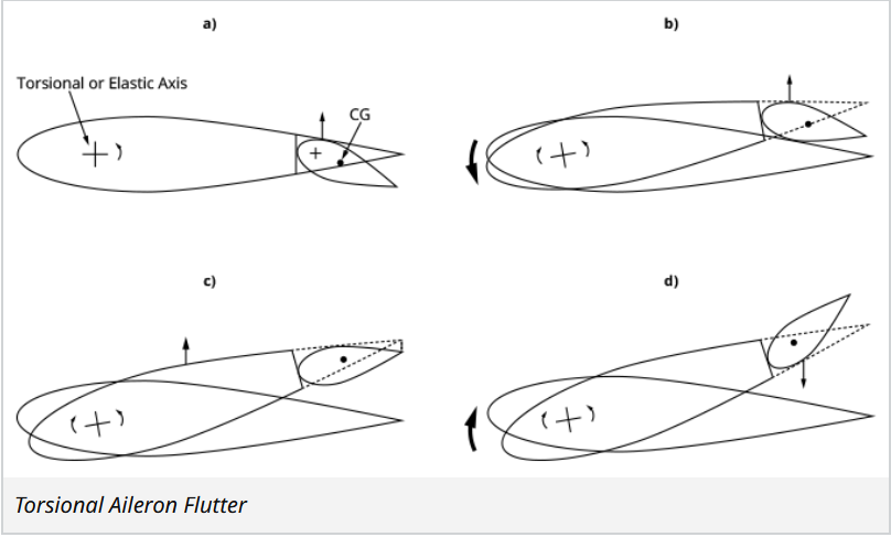
If it is aft of the hinge line, then there is an inertia felt, and an oscillation will follow. This oscillation is known as ‘flutter.’

Mass Balance Flutter
Torsional aileron flutter can be prevented either by mass-balancing the ailerons so that their CG is on, or slightly ahead of the hinge line, or by making the controls irreversible
Those aircraft with fully powered controls and no manual reversion do not require mass-balancing.
All other aircraft have their control surfaces mass-balanced.
Flexural Aileron Flutter
Caused by the movement of the aileron lagging behind the rise and fall of the outer portion of the wings as it flexes, thus tending to increase the oscillation.
Prevented by mass-balancing the aileron
Mass balance weight = The nearer the wing tip it is, the smaller the weight required
ALTERNATIVE = weight is distributed along the entire length of the aileron in the form of a leading-edge spar, thus increasing the stiffness of the aileron and preventing a concentrated weight from starting torsional vibrations
Control Surface Bias
involves applying a slight offset or pre-defined deflection to one or more control surfaces from their neutral positions. - IE ALWAYS PITCHING UP NATURALLY
It must be noted that after adjustment all trim position gauges on the flight deck indicate zero trim.
Aerodynamic Balance Panels
concerned with the effort required to move a control surface.
Forces acting on a control surface said to be from on point = Centre of Pressure (CP).
CP usually one-third of the chord length from the leading edge of the control surface / and positioned a little behind the hinge line of the surface / moment force must be overcome
Horn Balance and Inset Hinges
The horn is the part of the surface which is located forward of the hinge line and moves into the wind during deflection, aiding deflection
Second form of aerodynamic balance is the inset hinge / The surface forward of the hinge moves into the air stream during deflection, assisting the movement.
Balance Panels
It is assisted by seals to make sure the two chambers are completely separated. The static pressure from outside is allowed into the chambers via the slots.
In the example below, the static pressure in the upper chamber is less than the static pressure in the lower chamber during this deflection of the control surface.
This pressure difference produces a force on the balance panel which assists the deflection.

Speed of Sound (also known as Mach 1 BUT DON’T CONFUSE)
as temp gets colder with higher alt SPEED OF SOUND DECREASES IE -56 DEGREES = COLD
As an aircraft approaches the speed of sound, it experiences compressibility effects which manifest as shock wave formation, a sudden increase in drag, reduction in lift buffeting, and trim and control issues.

Subsonic, Transonic, and Supersonic Flight
read para
