1/27
Looks like no tags are added yet.
Express the sinusoidal AC equations of voltage and current

Derive the formula for root mean square
---
### Left Side (Derivation)
V(t)=Vmcos(ωt+δ)
Vrms=T1∫0Tv2(t)dt
=T1∫0TVm2cos2θdt
=T1∫0TVm2(2cos2θ+1)dt
=2VmT1∫0T(cos2θ+1)dt
=2Vm
---
### Right Side (Identities & Notes)
Top (Trigonometric Identities):
cos2x=cos2x−sin2x
cos2x=2cos2x−1
2cos2x+1=cos2x

Derive the expression for v(t) as a phasor
Left Side (Mathematical Derivation)
Euler's Identity:
ejθ=cosθ+jsinθ
Time-domain Voltage:
v(t)=Vmcos(ωt+δ)
Substitution (using Vm=2VrmsVm=2Vrms):
=2⋅Vrms⋅Re[ejθ]
Expanding the angle θθ:
=2⋅Vrms⋅Re[ej(ωt+δ)]
Separating time and phase components:
=2⋅Vrms⋅Re[ejωt⋅ejδ]
Phasor Definition (V‾V):
V‾=2⋅Vrms⋅ejδ
Polar Form:
=2⋅Vrms∠δv
Rectangular Form (using Euler's):
=2⋅Vrms[cosδv+jsinδv]
Right Side (Phasor Diagram)
A complex plane diagram is drawn with:
Axes: Real axis (ReRe) pointing right, Imaginary axis (ImIm) pointing up.
Vector V‾V: A red arrow originating from (0,0)(0,0) at an angle δvδv.
Horizontal Component: Labeled as VcosδvVcosδv along the Real axis.
Vertical Component: Labeled as jVsinδvjVsinδv along the Imaginary axis.
![<p><strong>Left Side (Mathematical Derivation)</strong></p><ol><li><p class="whitespace-pre-wrap"><strong>Euler's Identity:</strong><br><span style="font-family: KaTeX_Main, "Times New Roman", serif; line-height: 1.2; font-size: 1.21em;">ejθ=cosθ+jsinθ</span></p></li><li><p class="whitespace-pre-wrap"><strong>Time-domain Voltage:</strong><br><span style="font-family: KaTeX_Main, "Times New Roman", serif; line-height: 1.2; font-size: 1.21em;">v(t)=Vmcos(ωt+δ)</span></p></li><li><p class="whitespace-pre-wrap"><strong>Substitution (using </strong><span style="font-family: KaTeX_Main, "Times New Roman", serif; line-height: 1.2; font-size: 1.21em;"><strong>Vm=2Vrms<em>Vm</em>=2<em>V</em>rms</strong></span><strong>):</strong><br><span style="font-family: KaTeX_Main, "Times New Roman", serif; line-height: 1.2; font-size: 1.21em;">=2⋅Vrms⋅Re[ejθ]</span></p></li><li><p class="whitespace-pre-wrap"><strong>Expanding the angle </strong><span style="font-family: KaTeX_Main, "Times New Roman", serif; line-height: 1.2; font-size: 1.21em;"><strong>θ<em>θ</em></strong></span><strong>:</strong><br><span style="font-family: KaTeX_Main, "Times New Roman", serif; line-height: 1.2; font-size: 1.21em;">=2⋅Vrms⋅Re[ej(ωt+δ)]</span></p></li><li><p class="whitespace-pre-wrap"><strong>Separating time and phase components:</strong><br><span style="font-family: KaTeX_Main, "Times New Roman", serif; line-height: 1.2; font-size: 1.21em;">=2⋅Vrms⋅Re[ejωt⋅ejδ]</span></p></li><li><p class="whitespace-pre-wrap"><strong>Phasor Definition (</strong><span style="font-family: KaTeX_Main, "Times New Roman", serif; line-height: 1.2; font-size: 1.21em;"><strong>V‾<em>V</em></strong></span><strong>):</strong><br><span style="font-family: KaTeX_Main, "Times New Roman", serif; line-height: 1.2; font-size: 1.21em;">V‾=2⋅Vrms⋅ejδ</span></p></li><li><p class="whitespace-pre-wrap"><strong>Polar Form:</strong><br><span style="font-family: KaTeX_Main, "Times New Roman", serif; line-height: 1.2; font-size: 1.21em;">=2⋅Vrms∠δv</span></p></li><li><p class="whitespace-pre-wrap"><strong>Rectangular Form (using Euler's):</strong><br><span style="font-family: KaTeX_Main, "Times New Roman", serif; line-height: 1.2; font-size: 1.21em;">=2⋅Vrms[cosδv+jsinδv]</span></p></li></ol><div data-type="horizontalRule"><hr></div><p><strong>Right Side (Phasor Diagram)</strong></p><p class="whitespace-pre-wrap">A complex plane diagram is drawn with:</p><ul><li><p><strong>Axes:</strong> Real axis (<span style="font-family: KaTeX_Main, "Times New Roman", serif; line-height: 1.2; font-size: 1.21em;">ReRe</span>) pointing right, Imaginary axis (<span style="font-family: KaTeX_Main, "Times New Roman", serif; line-height: 1.2; font-size: 1.21em;">ImIm</span>) pointing up.</p></li><li><p><strong>Vector </strong><span style="font-family: KaTeX_Main, "Times New Roman", serif; line-height: 1.2; font-size: 1.21em;"><strong>V‾<em>V</em></strong></span><strong>:</strong> A red arrow originating from <span style="font-family: KaTeX_Main, "Times New Roman", serif; line-height: 1.2; font-size: 1.21em;">(0,0)(0,0)</span> at an angle <span style="font-family: KaTeX_Main, "Times New Roman", serif; line-height: 1.2; font-size: 1.21em;">δv<em>δv</em></span>.</p></li><li><p><strong>Horizontal Component:</strong> Labeled as <span style="font-family: KaTeX_Main, "Times New Roman", serif; line-height: 1.2; font-size: 1.21em;">Vcosδv<em>V</em>cos<em>δv</em></span> along the Real axis.</p></li><li><p><strong>Vertical Component:</strong> Labeled as <span style="font-family: KaTeX_Main, "Times New Roman", serif; line-height: 1.2; font-size: 1.21em;">jVsinδv<em>jV</em>sin<em>δv</em></span> along the Imaginary axis.</p></li></ul><p></p>](https://assets.knowt.com/user-attachments/194d7f78-b9e6-4fe3-8e40-d752890ccacc.jpg)
Derive the expression for the reactance of an inductor
Here is the transcription of the handwritten notes in the image:
---
### Derivation of Inductive Impedance
1. Basic Inductor Equation:
VL=L⋅dtdiL
2. Assume Sinusoidal Current:
iL=im⋅cos(ωt+θ)
3. Derivative of Current:
iL′=−ω⋅im⋅sin(ωt+θ)
4. Substitute into Voltage Equation:
VL=−ωL⋅im⋅sin(ωt+θ)
5. Convert Sine to Cosine (using sin(A)=cos(A−90∘)):
=−ωL⋅im⋅cos(ωt+θ−90∘)
6. Express in Complex Exponential Form:
=−ωL⋅im⋅ej(θ−90∘)
Alternative expansion shown:
=−ωL⋅im⋅ejθ⋅e−j90∘
7. Expand using Euler's Formula:
=−ωL⋅im⋅ejθ⋅[cos(−90∘)+jsin(−90∘)]
8. Simplify (cos(−90∘)=0,sin(−90∘)=−1):
=−ωL⋅im⋅ejθ⋅[0+j(−1)]
=−ωL⋅im⋅ejθ⋅(−j)
=jωL⋅im⋅ejθ
9. Final Phasor Relationship:
=jωL⋅I
---
### Conclusion (Right Side)
IVL=jωL
XL=jωL
![<p>Here is the transcription of the handwritten notes in the image:</p><p>---</p><p>### <strong>Derivation of Inductive Impedance</strong></p><p>1. <strong>Basic Inductor Equation:</strong></p><p> $$V_L = L \cdot \frac{di_L}{dt}$$</p><p>2. <strong>Assume Sinusoidal Current:</strong></p><p> $$i_L = i_m \cdot \cos(\omega t + \theta)$$</p><p>3. <strong>Derivative of Current:</strong></p><p> $$i_L' = -\omega \cdot i_m \cdot \sin(\omega t + \theta)$$</p><p>4. <strong>Substitute into Voltage Equation:</strong></p><p> $$V_L = -\omega L \cdot i_m \cdot \sin(\omega t + \theta)$$</p><p>5. <strong>Convert Sine to Cosine (using $\sin(A) = \cos(A - 90^\circ)$):</strong></p><p> $$= -\omega L \cdot i_m \cdot \cos(\omega t + \theta - 90^\circ)$$</p><p>6. <strong>Express in Complex Exponential Form:</strong></p><p> $$= -\omega L \cdot i_m \cdot e^{j(\theta - 90^\circ)}$$</p><p> </p><p> <em>Alternative expansion shown:</em></p><p> $$= -\omega L \cdot i_m \cdot e^{j\theta} \cdot e^{-j90^\circ}$$</p><p>7. <strong>Expand using Euler's Formula:</strong></p><p> $$= -\omega L \cdot i_m \cdot e^{j\theta} \cdot [\cos(-90^\circ) + j\sin(-90^\circ)]$$</p><p>8. <strong>Simplify ($\cos(-90^\circ)=0, \sin(-90^\circ)=-1$):</strong></p><p> $$= -\omega L \cdot i_m \cdot e^{j\theta} \cdot [0 + j(-1)]$$</p><p> $$= -\omega L \cdot i_m \cdot e^{j\theta} \cdot (-j)$$</p><p> $$= j\omega L \cdot i_m \cdot e^{j\theta}$$</p><p>9. <strong>Final Phasor Relationship:</strong></p><p> $$= j\omega L \cdot \underline{I}$$</p><p>---</p><p>### <strong>Conclusion (Right Side)</strong></p><p>$$\frac{\underline{V}_L}{\underline{I}} = j\omega L$$ </p><p>$$X_L = j\omega L$$ </p>](https://assets.knowt.com/user-attachments/bc7b529c-d3ec-41b5-b852-f02e47bce3e7.jpg)
Derive the expression for the reactance of a capacitor
Here is the transcription of the handwritten notes in the image:
---
### Derivation of Capacitive Impedance
1. Basic Capacitor Equation:
iC=C⋅dtdvc
2. Assume Sinusoidal Voltage:
v(t)=Vmcos(ωt+θ)
3. Derivative of Voltage:
v′=−ωVmsin(ωt+θ)
4. Substitute into Current Equation:
iC=−ωC⋅Vmsin(ωt+θ)
5. Convert Sine to Cosine (using sin(A)=cos(A−90∘)):
=−ωC⋅Vmcos(ωt+θ−90∘)
6. Express in Complex Exponential Form:
=−ωC⋅Vmej(ωt+θ−90∘)
7. Separate Time and Phase Components:
=−ωC⋅Vm⋅ejωt⋅ejθ⋅e−j90∘
8. Expand using Euler's Formula:
=−ωC⋅Vm⋅ejωt⋅ejθ⋅[cos(−90∘)+jsin(−90∘)]
9. Simplify (cos(−90∘)=0,sin(−90∘)=−1):
=−ωC⋅V⋅(−j)
10. Final Phasor Relationship:
iC=jωC⋅V
---
### Conclusion (Right Side)
iCV=jωC1=ωC−j
XC=ωC−j
![<p>Here is the transcription of the handwritten notes in the image:</p><p>---</p><p>### <strong>Derivation of Capacitive Impedance</strong></p><p>1. <strong>Basic Capacitor Equation:</strong></p><p> $$i_C = C \cdot \frac{dv_c}{dt}$$</p><p>2. <strong>Assume Sinusoidal Voltage:</strong></p><p> $$v(t) = V_m \cos(\omega t + \theta)$$</p><p>3. <strong>Derivative of Voltage:</strong></p><p> $$v' = -\omega V_m \sin(\omega t + \theta)$$</p><p>4. <strong>Substitute into Current Equation:</strong></p><p> $$i_C = -\omega C \cdot V_m \sin(\omega t + \theta)$$</p><p>5. <strong>Convert Sine to Cosine (using $\sin(A) = \cos(A - 90^\circ)$):</strong></p><p> $$= -\omega C \cdot V_m \cos(\omega t + \theta - 90^\circ)$$</p><p>6. <strong>Express in Complex Exponential Form:</strong></p><p> $$= -\omega C \cdot V_m e^{j(\omega t + \theta - 90^\circ)}$$</p><p>7. <strong>Separate Time and Phase Components:</strong></p><p> $$= -\omega C \cdot V_m \cdot e^{j\omega t} \cdot e^{j\theta} \cdot e^{-j90^\circ}$$</p><p>8. <strong>Expand using Euler's Formula:</strong></p><p> $$= -\omega C \cdot V_m \cdot e^{j\omega t} \cdot e^{j\theta} \cdot [\cos(-90^\circ) + j\sin(-90^\circ)]$$</p><p>9. <strong>Simplify ($\cos(-90^\circ)=0, \sin(-90^\circ)=-1$):</strong></p><p> $$= -\omega C \cdot V \cdot (-j)$$</p><p>10. <strong>Final Phasor Relationship:</strong></p><p> $$i_C = j\omega C \cdot V$$</p><p>---</p><p>### <strong>Conclusion (Right Side)</strong></p><p>$$\frac{\underline{V}}{\underline{i}_C} = \frac{1}{j\omega C} = \frac{-j}{\omega C}$$ </p><p>$$X_C = \frac{-j}{\omega C}$$ </p>](https://assets.knowt.com/user-attachments/4b7f1e06-6a06-4bd2-8fe0-bc941247ca9b.jpg)
Derive the formula for insant power in terms of avg power and reactant power
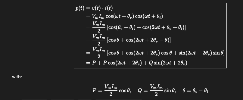
Derive the equation for the instantaneous power of a resistor
pR(t)=P+Pcos(2ωt+2θ)
=P[1+cos(2ωt+2θ)]
![<p>$$p_R(t) = P + P \cos(2\omega t + 2\theta)$$ </p><p>$$= P \left[ 1 + \cos(2\omega t + 2\theta) \right]$$</p>](https://assets.knowt.com/user-attachments/44ef4b06-2492-4919-aeae-5926d6c9f369.png)
Derive the equation for instant power of an inductor
pL=Qsin(2ωt+2θ)θv−θi=β=90∘
=2VmImsin(β)sin(2ωt+2θ)
=2VmImsin(2ωt+2θ)orVrmsIrmssin(2ωt+2θ)

Derive the equation for instant power of a capacitor
pc=Qsin(2ωt+2σ)where β=−90∘
=2VmImsin(β)sin(2ωt+2σ)
=−2VmImsin(2ωt+2σ)

Break down the formula for instant power
1. Real (Average) Power
In-phase Current Component:
Ir=Irmscos(δ−β)=2Imcos(δ−β)
Real Power (P):
P=2VmImcos(δ−β)
Unit:
Unit=Watt [W]
2. Reactive Power
Quadrature Current Component:
Ix=Irmssin(δ−β)=2Imsin(δ−β)
Reactive Power (Q):
Q=2VmImsin(δ−β)
Unit:
Unit=VAR (volt-ampere reactive)
![<p><strong>1. Real (Average) Power</strong></p><ul><li><p><strong>In-phase Current Component:</strong></p><p>$$I_r = I_{\text{rms}} \cos(\delta - \beta) = \frac{I_m}{\sqrt{2}} \cos(\delta - \beta)$$</p></li><li><p><strong>Real Power (</strong><span><strong>$P$</strong></span><strong>):</strong></p><p>$$P = \frac{V_m I_m}{2} \cos(\delta - \beta)$$</p></li><li><p><strong>Unit:</strong></p><p>$$\text{Unit} = \text{Watt } [\text{W}]$$</p></li></ul><p><strong>2. Reactive Power</strong></p><ul><li><p><strong>Quadrature Current Component:</strong></p><p>$$I_x = I_{\text{rms}} \sin(\delta - \beta) = \frac{I_m}{\sqrt{2}} \sin(\delta - \beta)$$</p></li><li><p><strong>Reactive Power (</strong><span><strong>$Q$</strong></span><strong>):</strong></p><p>$$Q = \frac{V_m I_m}{2} \sin(\delta - \beta)$$ </p></li><li><p><strong>Unit:</strong></p><p>$$\text{Unit} = \text{VAR } (\text{volt-ampere reactive})$$ </p></li></ul><p></p>](https://assets.knowt.com/user-attachments/1b16ddd4-1d89-42c6-9d3d-c51e5de7649c.png)
Describe the power factor
1. Equations
Power Factor (pf):
pf=cos(δ−β)
Reactive Factor (rf):
rf=sin(δ−β)
2. Operating ConditionsLeading / Capacitive Load
β>δ
Current leads voltage:
θi>θv
The phase difference is negative:
δ−β<0
Resulting in a negative reactive factor:
rf<0
Lagging / Inductive Load
δ>β
Current lags voltage:
θv>θi
The phase difference is positive:
δ−β>0
Resulting in a positive reactive factor:
rf>0
Conclusion
β>δvs.δ>β

Describe and break down complex power
1. Definition & Trigonometric Form
Complex power S is defined as the sum of real power P and reactive power Q:
S=P+jQ
Using maximum peak values Vm and Im, and phase difference θ=θv−θi:
S=2VmImcos(θ)+j2VmImsin(θ)
2. Converting to RMS & Exponential Form
Using Euler's identity:
ejθ=cosθ+jsinθ
Converting peak values to RMS:
V=2Vm
I=2Im
Rewriting the expression:
S=2VmImejθ
S=(2Vm)(2Im)ej(θv−θi)
S=VIej(θv−θi)
3. Splitting into Phasors
Separate the exponential term into individual voltage and current components:
S=(Vejθv)⋅(Ie−jθi)
Since:
V=Vejθv
I∗=Ie−jθi
We get:
S=V⋅I∗
In polar notation:
S=S∠(θv−θi)
4. Expressing in Terms of Impedance
Using Ohm's Law in the phasor domain:
V=I⋅Z
I=ZV
In terms of Current:
S=(I⋅Z)⋅I∗
Since:
I⋅I∗=∣I∣2
The final expression is:
S=∣I∣2Z
In terms of Voltage:
Taking the conjugate of both sides:
I∗=(ZV)∗=Z∗V∗
Substituting back into complex power:
S=V(Z∗V∗)
Since:
V⋅V∗=∣V∣2
The final expression is:
S=Z∗∣V∣2

Describe what is meant by load convention
Current enters positive terminal of circuit element
Power is absorbed if P/Q is positive
Power is delivered if P/Q negative

Describe what is meant by generator convention
Current leaves positive terminal of circuit element
Power is delivered if P/Q is positive
Power is absorbed if P/Q is negative

Describe the concept of power correction
S = VI*
S / V = I*
pf = cos( θ )
P = 2VmIm cos (θ)
increasing pf increases P which increases S
if S increases and V is constant, I* is decreasing
therefore power correction is used to decrease total current flowing (which reduces wastage in the form of heat, etc)

Describe the process of writing nodal equations in matrix form
Mark a reference node.
All essential nodes' voltages are with respect to the reference node.
For every voltage source in series with an impedance:
Transform it to a current source in parallel with the impedance.
Convert impedances into admittances.
Use the following format:
YV=I
For Y (Admittance Matrix):
Ykk= sum of admittances connected to node k
Ykn= negative sum of admittances directly between nodes <span>k</span>andn
For V (Node Voltage Vector):
Vn0= node voltage for node n relative to reference node 0
For I (Current Source Vector):
In= net sum of source currents connected to node n (entering node is usually + , leaving node is −)

Draw the basic template of a balanced three phase circuit. State its characteristics
All magnitudes are equal
All voltages have a phase difference of 120°
Line to neutral voltages - Ean, Ecn, Ebn represent the voltage between their respective nodes and the neutral node
Ean has a phase difference of 0
Ebn has a phase difference of -120
Ecn has a phase difference of 120
Line to line voltages - Eab = Ean - Ebn
Other similiar voltages are about the same

Draw 3 phase voltages connected to a wye config

Draw three phase voltages connected to a delta config

Derive the equation for the conversion of line to neutral TO line-to-line voltages
Eab=Vp∠0∘−Vp∠−120∘
=Vp−Vp⋅e−j120∘
=Vp[1−e−j120∘]
=Vp[1−(cos(120∘)−jsin(120∘))]
=Vp[1−(−21−j23)]
=Vp[1+21+j23]
=Vp[23+j23]
=Vp[3∠30∘]
=3Vp∠30∘
Derive the equation for the conversion of line to neutral current, Ia TO line-to-line currents
Ia=Ip−Ip∠120∘
=Ip[1−ej120∘]
=Ip[1−(cos(120∘)+jsin(120∘))]
=Ip[1−(−21+j23)]
=Ip[1+21−j23]
=Ip[23−j23]
=Ip[3∠−30∘]
=3Ip∠−30∘
State the equation for line to neutral current of a node a
in wye config
Ia = Ean / Zy
State the equation for line to neutral current of a node a
in delta config
Ia = -Iac * Iab
State the equation for line to line current of a Iab
in delta config
Iab = Eab / ΔZ
Eab = Ean - Ebn
State the equation for the conversion of a wye impedance to a delta impedance
Zy = 3ZΔ
Convert a wye 3-phase to its equivalent line-to-neutral circuits

Describe the power of a three phase circuit
Sa=VanIa∗
=Van∠δ⋅Ia∠−β
=VanIa∠(δ−β)
S3ϕ=Sa+Sb+Sc
=3Sϕ
=3VanIa∠(δ−β)
=3VanIa∗
=3VanIa[cos(δ−β)+jsin(δ−β)]
=3VanIacos(δ−β)+j3VanIasin(δ−β)
P=Re{S3ϕ}=3VanIacos(δ−β)
Q=Im{S3ϕ}=3VanIasin(δ−β)
∣S∣=3VanIa
![<p>$$S_a = \underline{V}_{an} \underline{I}_a^*$$ </p><p>$$= V_{an} \angle \delta \cdot I_a \angle -\beta$$</p><p>$$= V_{an} I_a \angle (\delta - \beta)$$</p><p>$$S_{3\phi} = S_a + S_b + S_c$$</p><p>$$= 3 S_\phi$$</p><p>$$= 3 V_{an} I_a \angle (\delta - \beta)$$</p><p>$$= 3 \underline{V}_{an} \underline{I}_a^*$$</p><p>$$= 3 V_{an} I_a \left[ \cos(\delta - \beta) + j \sin(\delta - \beta) \right]$$</p><p>$$= 3 V_{an} I_a \cos(\delta - \beta) + j 3 V_{an} I_a \sin(\delta - \beta)$$</p><p>$$P = \operatorname{Re}\{S_{3\phi}\} = 3 V_{an} I_a \cos(\delta - \beta)$$</p><p>$$Q = \operatorname{Im}\{S_{3\phi}\} = 3 V_{an} I_a \sin(\delta - \beta)$$</p><p>$$\vert{}S\vert{} = 3 V_{an} I_a$$</p>](https://assets.knowt.com/user-attachments/15f0c25c-488d-4988-9fc1-7af7429231a1.png)
Describee the advantages of a balanced 3-phase system over a single phase system



