resistive circuits
DP Physics
Resistive Circuits Practice
Background 1
If there is a potential difference between two points, charges will rearrange in order to decrease the energy imbalance if allowed to do so. Conductors are materials that allow charge to move. Insulators do not allow this motion. Inside a conductor, it is actually free electrons that are able to move. However, we use the concept of “conventional current” when discussing circuits. Conventional current is the flow of positive charge through the wire, so it points from the positive side of the potential difference to the negative side. The current is the amount of charge that passes a given point for each unit of time. It can be written as:

Our base unit is the ampere (A). Originally, the ampere was defined as  when the coulomb was considered to be the fundamental unit. The ampere is now considered to be the fundamental unit and the coulomb is the derived unit. The current moving through a wire comes from averaging the motion of the charges that are moving. We use the equation

where n is the number of charge carriers per unit volume, A is the cross-sectional area of the wire, v is the drift speed of the moving charges, and q is the charge for the given charge carrier.
Calculations 1
The current in a wire is 1.5 mA.
Calculate the amount of charge that moves through a given area in 5 s.
Determine the number of electrons that move through this area in 5 s.
Proton beam therapy is a cancer treatment method that involves bombarding a tumor with a beam of high energy protons. During a typical treatment 2x10⁶ protons may be directed into a tumor over a time span of approximately 1 minute. Calculate the current of this beam.
The drift speed through a wire with radius r is v. The radius is doubled to 2r and the current stays constant. Determine the new drift speed.
A copper wire of diameter of 0.65 mm carries a current of 0.25 A. There are 8.5x1028 charge carriers in each cubic meter of copper. The charge on each charge carrier electron is 1.6x10⁻¹⁹ C. Calculate the drift speed of the charge carriers.
Background 2
Ohm’s law is the relationship between the potential difference that causes charges to move through a conductor and the resulting current. This relationship holds as long as the device doesn’t significantly change its temperature. The equation is  . If we rearrange the equation, we can get a definition of the resistance of a device
  .
.
The resistance of a device is given by the potential difference needed to get one unit of current in the device. The structure of the device can impact the resistance. The material has a property called the resistivity ( ) of the substance. If the cross sectional area of a device is increased, the resistance would decrease. If the length of the device is increased, the resistance would increase. A way to write this relationship is
  . We could also rearrange the equation to get a representation of the resistivity

Calculations 2
The potential difference across a resistor is 5 V and the current through the resistor is 1 mA. Calculate the resistance.
Two resistors with resistance 2 Ω and 5 Ω have a current of 1 A running through them. Calculate the potential difference across each resistor.
A 5 cm long, 5 mm diameter wire has a resistance of 1 Ω. Calculate the resistivity of the wire.
Two different types of material are used to make wires of the same length L and resistance R, one which has a diameter of 2 mm and the other has a diameter of 4 mm.
Compare the resistivity of each wire material.
Compare the resistance of the wires if they have the same length and diameter.
The resistivity of copper is 1.72x10⁻⁸ Ω m. Calculate the resistance of a 20.0 cm wire that has a diameter of 1.60 mm.
A given resistor has a resistivity of 1.23 Ω m. It is 1.5 cm long and has a diameter of 5.0 mm.
Calculate the resistance.
Determine the current through the resistor when a 6.0 V potential difference is applied across the resistor.
Background 3
The lab activities from this unit can lead us to some conclusions about the currents and voltages in circuits.
The currents through all elements along the same line (in series with one another) are the same.
The total current coming into a junction equals the total current out of a junction.
Objects in parallel with one another have the same potential difference.
Currents at a junction will divide to satisfy the voltage requirements for the elements.
The total voltage around a closed loop is zero.
These results can be used to derive relationships of groups of elements based on their arrangement relative to one another. Combinations of resistors that are in series with one another act as the sum of the individual resistances. Combinations of resistors that are in parallel with one another act as the inverse of the sum of the inverses of the individual resistances.
Series Circuits | Parallel Circuits |
|
|
|
|
|
|


Calculations 3
A circuit is set up as shown.
Calculate the effective resistance of the circuit.
Calculate the current through the 8 Ω resistor.
Calculate the current through the 4 Ω resistor.
Calculate the potential difference across each resistor.
A circuit is set up as shown.
Calculate the equivalent resistance in the circuit.
Determine the amount of current that will leave the battery.
Indicate the direction of the current on the circuit.
What is the potential drop across the 4 Ω resistor?
Determine the current through the 4 Ω resistor.
What is the potential drop across the 8 Ω resistor?
Determine the current through the 8 Ω resistor
Use the circuit at the right to answer the following:
Determine the equivalent resistance in the circuit.
Calculate the amount of current leaving the battery.
Indicate the direction of the current on the circuit.
What is the current through the 4 Ω resistor?
Calculate the potential drop across the 4 Ω resistor.
Determine the potential drop across the 10 Ω resistor.
Calculate the current through the 10 Ω resistor.
What is the potential drop across the 15 Ω resistor?
Determine the current through the 15 Ω resistor.
R1 = 4.0 Ω, R2 = 8.0 Ω, and R3 = 4.0 Ω. Use the circuit at the right to answer the following:
Determine the equivalent resistance in the circuit.
Determine the amount of current that will leave the battery.
Indicate the direction of the current on the circuit.
What is the potential drop across R3?
Calculate the current through R3.
What is the current through R1?
Calculate the potential drop across R1.
What is the current through R2?
Calculate the potential drop across the R2?
R1 = 5.0 Ω, R2 = 8.0 Ω, R3 = 7.0 Ω and R4 = 30.0 Ω. Use the circuit at the right to answer the following:
Determine the equivalent resistance in the circuit.
Calculate the current out of the battery.
Describe quantitatively what happens to the current at point p.
Determine the potential drop across each of the resistors.
Given the circuit shown with three resistors of R, 2R, and 3R connected to an ideal battery with a potential difference of VB. Calculate the potential difference across each resistor.
Given the circuit shown with three resistors of R, 2R, and 3R connected to an ideal battery with a potential difference of VB. Calculate the current through each resistor.
A single 20 Ω resistor is connected to a 10 V power supply.
Suppose another 20 Ω resistor is connected in series with the first resistor.
Describe the impact on the current out of the power supply.
Describe the impact on the current through the original resistor.
Suppose the new 20 Ω resistor is connected in parallel with the first resistor instead.
Describe the impact on the current out of the power supply.
Describe the impact on the current through the original resistor.
Background 4
Resistors convert energy into heat. Joule’s law describes the rate of conversion

Putting Joule’s law together with Ohm’s law gives multiple iterations of the same equations

Calculations 4
Sketch the graphs that would show each of the following relationships:
Power vs. Voltage with resistance constant.
Power vs. Voltage with current constant.
Power vs. Current with voltage constant.
Power vs. Current with resistance constant.
A 12 volt battery has a 150 Ω resistor connected across its terminals.
Calculate the current through the resistor.
Calculate the power for the resistor.
Determine the amount of energy dissipated in 20 minutes of use.
An appliance is rated for 2.5 A at 120 V.
Calculate the electric power required.
Determine the effective resistance of the appliance.
A hair dryer is rated for 1200 W at 120 V.
Determine the amount of current the dryer draws.
Determine the effective resistance of the dryer.
Two resistors of 100 Ω and 25 kΩ are rated for maximum wattages of 1.5 W and 0.25 W respectively. Calculate the maximum current for each.
What is the maximum power consumption of a 9.0 V transistor radio that draws a maximum of 400 mA of current?
A toaster that draws 5 amps of current when plugged into a 120-volt wall socket.
Calculate the resistance in the toaster.
Determine the amount of energy used if the toaster is on for 2.0 minutes.
Consider this circuit.
Calculate the effective resistance of the circuit.
Calculate the voltage across each resistor.
Calculate the current through each resistor.
Calculate the power dissipated by each resistor.
Consider this circuit.
Calculate the effective resistance of the circuit.
Calculate the voltage across each resistor.
Calculate the current through each resistor.
Calculate the power dissipated by each resistor.
Consider this circuit.
Calculate the effective resistance of the circuit.
Calculate the voltage across each resistor.
Calculate the current through each resistor.
Calculate the power dissipated by each resistor.
Background 5
To this point, we have considered all of the circuit elements to be ideal. A real battery can be considered to be the combination of an ideal cell and an internal resistor. The potential difference across the ideal portion of the battery is called the electromotive force ( ). The terminal potential difference between the ends of the battery when a current is flowing in the circuit can be written as

In order to measure the potential difference across an element, a voltmeter is attached in parallel to the element. In order to avoid disrupting the circuit when taking measurements, the resistance in the voltmeter is very large. An ammeter is placed in series with the element the resistance should have a very small resistance. In both of these cases, real devices impact the performance of the circuit.
Calculations 5
A circuit is wired as shown. The battery has internal resistance 0.5 Ω and EMF 12 V.
Calculate the current in the circuit.
Determine the terminal voltage of the battery.
Calculate the power dissipated by the internal resistance of the battery.
Describe the effect this power dissipation would have on the battery.
An ideal 12 V battery is wired in series with an ammeter, 18 Ω, and 6 Ω resistor.
Draw the circuit diagram.
Calculate the current read by the ammeter if it is ideal.
Now assume the ammeter is non-ideal, and has an internal resistance of 0.5 Ω. Calculate the effective resistance of this circuit and the current reading for the ammeter.
Given the circuit diagram.
Determine the voltage read by the voltmeter if it is ideal.
Calculate the current through the 180 Ω resistor and the voltmeter.
Now assume the voltmeter is non-ideal, and has an internal resistance of 1000Ω. Calculate the new effective resistance of this circuit and determine the voltage read by the voltmeter.
Calculate the current through the 180 Ω resistor and the voltmeter.
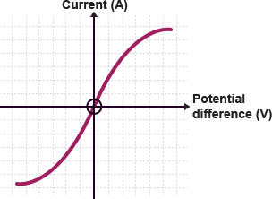
The current vs voltage graph for a tungsten filament bulb is given on the right.
Determine how the resistance of the filament changes with voltage.
Explain how this is different from the resistors you have encountered.
What physical property of the filament may cause this behavior?
A student wants to measure the current through a 3300 Ω resistor wired to a 10 V power supply. The student accidentally uses the ammeter in parallel rather than series. Assume the ammeter has an internal resistance of 0.5 Ω.
Draw the circuit diagram.
Calculate the current that flows through the ammeter.
In the ammeter, there is a fuse designed to break at 0.5 A of current. Does the fuse break?
Explain why the fuse is designed to break.
Circuit breakers are resettable automatic switches that open when a given current value is exceeded. A 1100 W toaster, 750 W coffee maker, and a 1250 W microwave oven are turned on in a kitchen. As the drawing shows, they are all through a 20 A circuit breaker to a 120 V power supply.
Determine the combinations of appliances that will not cause the circuit breaker to open.
Explain the purpose of the circuit breaker.
Compare a circuit breaker and a fuse.