TestOut PC Pro 7.0
3.2.6 Peripheral and Video Cables Facts
This lesson covers the following topics:
Modern video connections
Older video connections
Other connections
Legacy connections
Apple connections
Modern Video Connections
Just like everything else in the computer world, ports continue to evolve in type and performance. Be familiar with the following ports and connectors; where they are located; and the devices they support.
Port/Cable | Description |
|---|---|
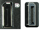
| DisplayPort is a royalty-free standard created by the Video Electronic Standards Association (VESA). It is found on PCs rather than on TVs. DP:
|
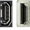
| HDMI is a forward compatible standard developed and promoted by the consumer electronics industry. It is compatible with LCD monitors and most components in a modern entertainment system. HDMI:
|

| The USB port is one of the most common computer ports for local communications. USB ports are used to connect a variety of devices:
|
Older Video Connections
Connectivity with ports and cables continues to evolve, but you may be asked to use older PCs. You should be familiar with the following older ports and connectors; where they are located; and the devices they support.
Port/Cable | Description |
|---|---|
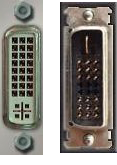
| DVI is a popular connection to carry analog and digital through the same white video cable. DVI:
|
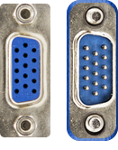
| VGA is a blue serial connector that has been around for a long time. VGA connected external display devices such as CRT monitors, projectors, and some of the first models of LCD monitors. VGA:
|

| The Separated Video (s-video) port is used for connecting external displays. It has slightly better picture quality than a Radio Corporation of America (RCA) video port. |
Other Connections
You should be familiar with the following ports and connectors; where they are located; and the devices they support.
Port/Cable | Description |
|---|---|
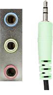
| Audio jacks are used to send or receive analog audio signals. Audio jacks use 3.5 mm Tip Ring Sleeve (TRS) connectors to connect audio devices such as:
Audio jacks use a common color code to denote the port type:
|


| The S/PDIF port is used to send a digital audio signal to high-end audio devices such as home theater systems or Dolby Digital surround sound systems.
|
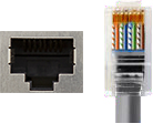
| RJ45 ports are used to create Ethernet networks by connecting multiple computers and networking devices. RJ45 ports have eight connector pins. |
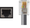
| RJ11 ports are used by telephones and modems to send analog signals. RJ11 ports have four connector pins. |
Legacy Connections
Computer ports that have been replaced by newer technology are considered legacy ports. Legacy ports are still widely used and provide functionality, but are neither as fast nor as efficient as the ports that have replaced them. The following table describes common legacy ports.
Port/Cable | Description |
|---|---|

| The PS/2 port connects older PS/2 keyboard or mouse devices.
|
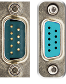
| The serial port can connect many different serial devices such as a printer, barcode scanner, router, dial-up modem, or serial mouse. Serial ports are commonly used to connect a console port or management port to configure and manage networking devices.
|
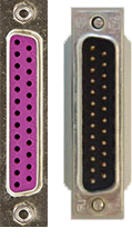
| The parallel port connects older devices that use a parallel interface, such as printers, hard drives, and gamepads.
|
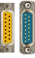
| The DB-15 is a gaming port used by legacy game pads, joysticks, and MIDI devices.
|
Apple Connections
You should be familiar with the following Apple ports and connectors; where they are located; and the devices they support.
Connector | Description |
|---|---|
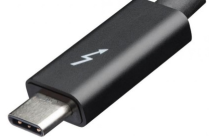
| Thunderbolt is the brand name of a hardware interface developed by Intel collaborating with Apple. It supplies power for connecting external displays to a computer.
|
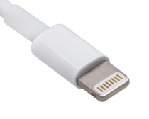
| Lightning (created by Apple) connects mobile devices like iPhones, iPads, and iPods to a host.
|
Hard Drive Cable Facts
This lesson covers the following topics:
Internal hard drive connections
Common external cables
Internal Hard Drive Connections
Hard drive and data storage systems require the proper connector types and cables. Each device also needs a power connection. The following table describes the main types of internal hard drive cables:
Serial Advanced Technology Attachment (SATA)
Small Computer System Interface (SCSI)
Serial Attached SCSI (SAS)
Integrated Drive Electronics (IDE)
Molex
Image | Type | Description |
|---|---|---|
Internal cable and connectors | SATA | SATA, also known as Serial ATA, is frequently used in modern computers to connect hard drives to the motherboard.
|
Internal ribbon and 50-pin connector | SCSI | SCSI is usually found only in high-end servers, mainframe computers, and redundant array of independent discs (RAID) storage devices.
SCSI Parallel Interface (SPI) uses a parallel bus. It's the earliest SCSI interface and has been around for over 20 years. The standards have been revised numerous times and it is still used today.
SCSI interface can be confusing since implementation varies by manufacturer. The different interfaces are not compatible. |
Internal cable and connector | SAS | SAS is a point-to-point interface that uses a serial protocol. It's typically found in enterprise-level storage systems like RAID, tape drives, or dedicated servers.
SAS is a serial protocol for SCSI commands. |
Internal ribbon with 40-pin connector | IDE | IDE, also known as Parallel AT Attachment (PATA), is an older technology.
|
Male-to-female connector | Molex | Molex is a generalized name given to a common type of connector used to power internal computer components.
|
Common External Cables
An external interface on the hard drive mechanism determines how the drive enclosure connects to the computer. The following table describes common external cables used:
External SATA (eSATA)
SCSI
SAS
internet SCSI (iSCSI)
Image | Type | Description |
|---|---|---|
Male-to-male connectors | eSATA | eSATA creates a SATA connection in an external enclosure.
|
Male-to-male 68-pin connectors | SCSI | SCSI connects other hardware: hard drives, tape drives, CD-ROMS, scanners, and printers.
SCSI interfaces can be confusing because SCSI types offered by different manufacturers have different speeds, bus widths, and connectors. |
Small form factor (SFF) | SAS | SAS cables support emerging data storage technologies. SAS:
|
Small form-factor pluggable (SFP) 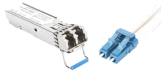 | iSCSI | iSCSI is used to access enterprise-class storage systems by carrying SCSI commands over TCP/IP network.
Fibre Channel over fibre-optic cable (shown)
|
Adapter and Converter Facts
TestOut PC Pro 7.0
3.2.9 Adapter and Converter Facts
Connector adapters and converters convert a particular connector type into one used by a component.
This lesson covers common adapters.
Common Adapters
You will commonly use adapters to connect a computer to a monitor. Adapters convert the connector of the output device (e.g., a laptop) into one the display (e.g., monitor) can use. The following table describes the most commonly used adapters and converters.
Adapter | Description |
|---|---|
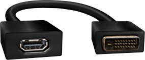
| Connects an HDMI cable to a DVI port. |
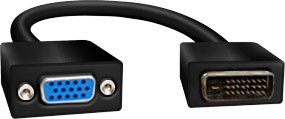
| Connects a VGA cable to a DVI port. |
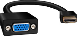
| Connects a VGA cable to an HDMI port. |
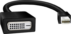
| Connects a DVI cable to a Thunderbolt port. |
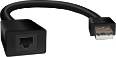
| Connects an RJ45 connector to a USB port. |
The manufacturer determines how an adapter or converter looks. Therefore, it is important to make sure that the adapter connection type and the connection end (e.g., a DVI female to an HDMI male) match the devices you are connecting.
Video And Capture Card Facts
TestOut PC Pro 7.0
3.11.6 Video and Capture Card Facts
Video cards process graphical information for output to an external display. The quality and speed have increased dramatically with PC gaming and cryptocurrency mining. A device called a capture card is growing in use to support streaming and the recording games and videos.
This lesson covers the following topics:
Integrated vs. dedicated video cards
Characteristics of video cards
Capture cards
Integrated vs. Dedicated Video Cards
You can implement video cards as a dedicated expansion board or integrated with other components.
Integrated video cards:
Integrate the graphics processing unit (GPU) with another hardware component (e.g., the central processing unit (CPU) or motherboard).
Share system memory for graphic processing.
Are less expensive than dedicated video cards, but are also less powerful.
Are installed in most pre-built PCs and found in most laptops. Integrated cards are also used in servers.
Dedicated video cards:
Are installed in an expansion slot on the motherboard.
Have a GPU and a dedicated, high-speed video memory bank.
Are more powerful than most integrated video cards, but are also more expensive.
Are used in cryptocurrency mining.
Allow multiple cards to be connected. This is called daisy chaining.
Characteristics of Video Cards
When selecting a video card, keep in mind the following characteristics:
Characteristic | Description |
|---|---|
Display connectors | Video cards have one or more connectors for attaching an external display. Always try to select a video card with connectors that match the display.
|
Display quality | Both the video card and the external display determine the quality of images and animation. When selecting a video card, consider resolution and refresh rate.
|
Processing capabilities | The GPU handles all video rendering tasks. GPUs are much more efficient at processing graphic data than a traditional CPU.
|
Memory | Dedicated video cards use high-speed memory to store graphic data. The amount of memory on the card affects performance as well as other characteristics.
|
Bus type | Video cards must be compatible with the expansion slots on the motherboard. Common slot types used by video cards include the following:
Motherboards with integrated graphics embed the functionality with the buses (e.g., PCIe, AGP, or PCI) on the system. |
Multi-GPUs | You can link video cards together. This allows you to share the graphic processing load between the two GPUs.
Some motherboards allow you to link an integrated graphics controller with a video card installed in the expansion slot; however, this offers a negligible performance boost. |
HDMI audio | HDMI cables can carry both video and audio signals; however, most video cards send only a video signal. You can use the following techniques to send an audio signal through the video card:
|
DirectX/Open Graphics Library | DirectX is a collection of application program interfaces (APIs) that improves graphic, animation, and multimedia creations.
OpenGL is an alternative standard to DirectX that is used by some applications. Most video cards support both DirectX and OpenGL. |
High-Bandwidth Digital Content Protection | HDCP is a method for protecting digital media. The purpose of HDCP is to prevent the interception and copying of protected data streams as they are sent from a playback device to a display device (e.g., from a DVD player to an HDTV).
|
Peripheral and Video Cables Facts Summary
Modern Video Connections
DisplayPort (DP): Supports multiple high-quality video/audio streams and resolutions up to 8194 x 4320. Compatible with HDMI, DVI, and most Mac devices.
HDMI: Transmits high-definition video and audio (up to 8 channels). Available in Type A (standard), Type C (mini), and Type D (micro).
USB: Commonly used for devices like mice, keyboards, cameras, printers, and webcams.
Older Video Connections
DVI: Supports both analog and digital signals, max resolutions of 1920 x 1200 (single-link) and 2560 x 1600 (dual-link).
VGA: Analog-only, lower quality with max resolution of 640 x 480.
S-Video: Provides better quality than RCA for connecting displays.
Other Connections
Audio Jack: 3.5 mm jacks for audio signals in audio devices (color coded).
S/PDIF: Digital audio connection for high-end systems (coaxial and fiber).
RJ45: Used for Ethernet networks; RJ11: for telephones/modems.
Legacy Connections
PS/2: Older keyboard and mouse connection; replaced by USB.
Serial (DB-9): Connects various serial devices; has become less common.
Parallel (DB-25): Older printer and external devices port; replaced by USB.
DB-15: Legacy gaming port for joysticks.
Apple Connections
Thunderbolt 3: Combines PCIe and DisplayPort; supports high data transfer rates.
Lightning: Connects mobile Apple devices to various peripherals.
Capture Cards
A capture card is a device used in tandem with a dedicated computer to capture on-screen content. The captured content is encoded for playback in either a livestream or a high-quality video file.
You can use capture cards with new and old video game consoles, as well as computers and cameras. Capture cards are most frequently used by video gamers and live streamers.
Connection Types
USB
PCIe
USB-C
Thunderbolt
Items needed
Primary device like a game console, computer, or digital camera.
A capture card with appropriate connection port matching the primary device.
An additional HDMI cable.
High-definition TV or monitor.
An encoding computer.
Capture card software.
Video Card Installation Facts
Dedicated Video Card Installation Process
Verify Compatibility: Ensure that the video card is compatible with the expansion slots on the motherboard.
Check Integrated Graphics: Determine if the motherboard has integrated graphics. If so, disable it in the CMOS configuration when installing a dedicated video card.
Install Primary Video Card: Insert the video card into the first open expansion slot.
For Multi-GPU Configurations (SLI or CrossFire):
Install the secondary video card in the next open expansion slot.
Link the two video cards together using the bridge clip.
Connect additional power connectors (6-pin, 8-pin, or 12-pin auxiliary power) to the video card(s). Note that some motherboards may have an additional power connector near the expansion slots used for multi-GPU setups.
Connect External Display: Use the appropriate cable to connect the external display to the video card. In a multi-GPU setup, connect the monitor to the primary (first) video card.
Complete Installation: Ensure all connections are made, turn on the computer, and check for proper functioning.
Install Drivers: Install video card drivers within the operating system.
Install Software: If using a multi-GPU configuration, install all necessary configuration software.